 />
/>
Control Robot Car with Hand Movements | ESP32 + Gyro Sensor + ESP-NOW
By Shail PathakIntroduction:
In this project, we’re going to build a gesture-controlled robot car using two ESP32 boards and a gyroscope sensor. You don’t need Bluetooth, Wi-Fi, or a mobile app — this robot moves just by tilting your hand!
We use the ESP-NOW protocol to send motion data from one ESP32 to another. It’s fast, lightweight, and works without a router. Whether you're a beginner or a tech enthusiast, this is a fun and exciting project to try.
What You’ll Learn:
By the end of this project, you’ll learn:
- How to use the gyroscope sensor to detect hand tilt
- How to set up ESP-NOW communication between two ESP32 boards
- How to control a robot’s motors wirelessly
- How to map motion data to motor speed and direction
- How to build a gesture-controlled vehicle
Project Overview:
We are building a wireless robot car that:
- Uses hand gestures to move
- Works with ESP-NOW (no Wi-Fi or internet required)
- Reads data from gyroscope
- Sends X and Y tilt values to another ESP32
- Controls two DC motors using an L298N motor driver
Required Components:
Here’s a list of the components you’ll need for this project:
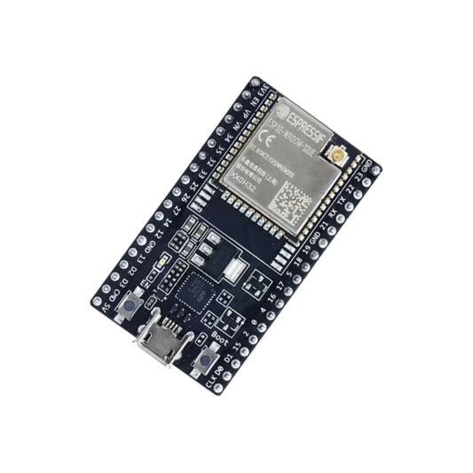
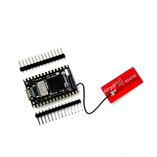
- Two ESP32 Boards
- Gyroscope Sensor
- L298N Motor Driver Module
- Robot Chassis kit
- Two Li-ion Battery
- Jumper Wires
- Two Breadboard
- USB Cable
Circuit Diagram:
Create two setups:
1. Transmitter ESP32 + Gyroscope sensor:
| Gyroscope Pin | ESP32 Pin |
|---|---|
| VCC | 3.3V |
| GND | GND |
| SDA | GPIO 21 |
| SCL | GPIO 22 |

2. Receiver ESP32 + L298N + Motors:
| L298N Pin | ESP32 Pin |
|---|---|
| IN1 | GPIO 13 |
| IN2 | GPIO 12 |
| IN3 | GPIO 14 |
| IN4 | GPIO 27 |
| ENA | GPIO 26 |
| ENB | GPIO 25 |
| VCC (L298N) | Battery + |
| GND | Battery - & ESP32 GND |

Hardware Setup – Step-by-Step Instructions:
Transmitter:
- Connect Gyroscope sensor to ESP32 as per the table.
- Mount the ESP32 and sensor on a glove or a small handheld board.
- Power the ESP32 via USB or battery.
Receiver:
- Connect motors to the L298N motor driver.
- Connect ESP32 to L298N inputs as per the table.
- Power L298N with a 7.4V or 12V battery.
- Connect battery ground to both L298N and ESP32.
Code:
Transmitter Code (ESP32 + Gyroscope):
#include <esp_now.h>
#include <WiFi.h>
#include <Wire.h>
#include <MPU6050.h>  // Install via Library Manager

MPU6050 mpu;

uint8_t receiverMacAddress[] = {0x40, 0x22, 0xD8, 0xFF, 0x7C, 0x7C};

struct PacketData {
  byte xAxisValue;
  byte yAxisValue;
  byte switchPressed;
};
PacketData data;

void OnDataSent(const uint8_t *mac_addr, esp_now_send_status_t status) {
  Serial.print("Send Status: ");
  Serial.println(status == ESP_NOW_SEND_SUCCESS ? "Success" : "Fail");
}

byte mapAccelToByte(int16_t accelValue) {
  // Convert -17000 to 17000 range into 0 to 254
  int mapped = map(accelValue, -17000, 17000, 0, 254);
  mapped = constrain(mapped, 0, 254);
  return (byte)mapped;
}

void setup() {
  Serial.begin(115200);
  Wire.begin();

  mpu.initialize();
  if (!mpu.testConnection()) {
    Serial.println("MPU connection failed");
    while (1);
  }

  Serial.println("MPU connected!");
  WiFi.mode(WIFI_STA);

  if (esp_now_init() != ESP_OK) {
    Serial.println("Error initializing ESP-NOW");
    while (1);
  }

  esp_now_register_send_cb(OnDataSent);

  esp_now_peer_info_t peerInfo = {};
  memcpy(peerInfo.peer_addr, receiverMacAddress, 6);
  peerInfo.channel = 0;
  peerInfo.encrypt = false;

  if (esp_now_add_peer(&peerInfo) != ESP_OK) {
    Serial.println("Failed to add peer");
    while (1);
  }
}

void loop() {
  int16_t ax, ay, az;
  mpu.getAcceleration(&ax, &ay, &az);

  data.xAxisValue = mapAccelToByte(ax);
  data.yAxisValue = mapAccelToByte(ay);
  data.switchPressed = 0;

  esp_err_t result = esp_now_send(receiverMacAddress, (uint8_t *)&data, sizeof(data));

  if (result != ESP_OK) {
    Serial.println("Error sending the data");
  }

  delay(100);
}
Receiver Code (ESP32 + Motor Driver):
#include <esp_now.h>
#include <WiFi.h>

// Motor pin definitions
#define IN1 13
#define IN2 12
#define IN3 14
#define IN4 27
#define ENA 26
#define ENB 25

#define enableRightMotor ENB
#define rightMotorPin1 IN3
#define rightMotorPin2 IN4

#define enableLeftMotor ENA
#define leftMotorPin1 IN1
#define leftMotorPin2 IN2

#define MAX_MOTOR_SPEED 200

const int PWMFreq = 1000;
const int PWMResolution = 8;
const int rightMotorPWMSpeedChannel = 4;
const int leftMotorPWMSpeedChannel = 5;

#define SIGNAL_TIMEOUT 1000

unsigned long lastRecvTime = 0;

struct PacketData {
  byte xAxisValue;
  byte yAxisValue;
  byte switchPressed;
};
PacketData receiverData;

bool throttleAndSteeringMode = false;

// Callback when ESP-NOW data is received
void OnDataRecv(const uint8_t * mac, const uint8_t *incomingData, int len) {
  if (len == 0) return;

  memcpy(&receiverData, incomingData, sizeof(receiverData));

  String inputData = "Values: " + String(receiverData.xAxisValue) + " " + String(receiverData.yAxisValue) + " " + String(receiverData.switchPressed);
  Serial.println(inputData);

  if (receiverData.switchPressed == true) {
    throttleAndSteeringMode = !throttleAndSteeringMode;
  }

  if (throttleAndSteeringMode) {
    throttleAndSteeringMovements();
  } else {
    simpleMovements();
  }

  lastRecvTime = millis();
}

void simpleMovements() {
  if (receiverData.yAxisValue <= 75) {
    rotateMotor(MAX_MOTOR_SPEED, MAX_MOTOR_SPEED);
  } else if (receiverData.yAxisValue >= 175) {
    rotateMotor(-MAX_MOTOR_SPEED, -MAX_MOTOR_SPEED);
  } else if (receiverData.xAxisValue >= 175) {
    rotateMotor(-MAX_MOTOR_SPEED, MAX_MOTOR_SPEED);
  }
  // Add more movement conditions as needed
}
How to Run the Code:
- Upload transmitter code to the first ESP32.
- Upload receiver code to the second ESP32.
- Power both boards.
- Tilt the transmitter (your hand) and observe the car moving in the corresponding direction.
Troubleshooting Tips:
- Double-check MAC address of the receiver board.
- Make sure both ESP32 boards are powered properly.
- Ensure proper connections of SDA/SCL and motor pins.
- Use Serial Monitor to debug and verify sensor readings.
Further Improvements:
- Add a button to switch between modes.
- Add battery level indicators.
- Use a more stable power source.
- Add obstacle detection using ultrasonic sensors.
Conclusion:
This project showcases how ESP32, Gyroscope sensor, and ESP-NOW can come together to build a unique wireless robot car controlled by hand gestures. It's educational, fun, and a great entry into the world of embedded systems and wireless robotics.
Output Preview:
- Car moves forward when hand tilts forward
- Car moves backward when hand tilts backward
- Car turns left/right based on hand tilt
- Fast and responsive wireless control using ESP-NOW