


vendor-unknown
Wireless remote using 2.4 GHz NRF24L01 Simple tutorial using NRF24L01 and Arduino uno - KT988
Wireless remote using 2.4 GHz NRF24L01 Simple tutorial using NRF24L01 and Arduino uno - KT988
SKU:KT988
100 in stock
Couldn't load pickup availability
- For Bulk Order Click Here
- Need Customer Support?
- Free Delivery Above 999/-
Note: In case you receive a damaged or faulty product, please return it in the original box with all foam and packaging. Returns will not be accepted if further damage occurs due to improper packing.
If you order a product that is currently in Preorder, and the price of that item increases in the future, you will be required to pay the difference in price.
For refund/return/replacement, call us at +91 95995 94520 or email us at support@rees52.com
Delivery Time
Delivery Time
- Delivery time with the Express Shipping option is 2-3 working days, and with the Standard Shipping option is 5-6 working days. It varies based on location, reliant on courier services.
- Delivery time if the order item is on Preorder Status is 15-20 working days.
COD (Cash on Delivery)
COD (Cash on Delivery)
- For COD you have to pay extra charges of Rs 350/- before the shipment. (We will share the company QR Code, UPI ID or Account details for the same)

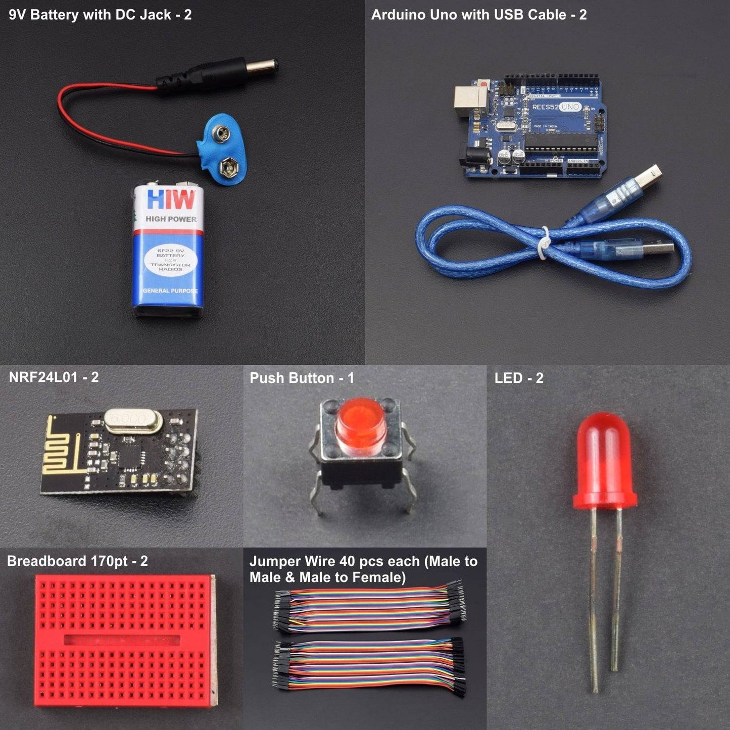
KIT INCLUDES:
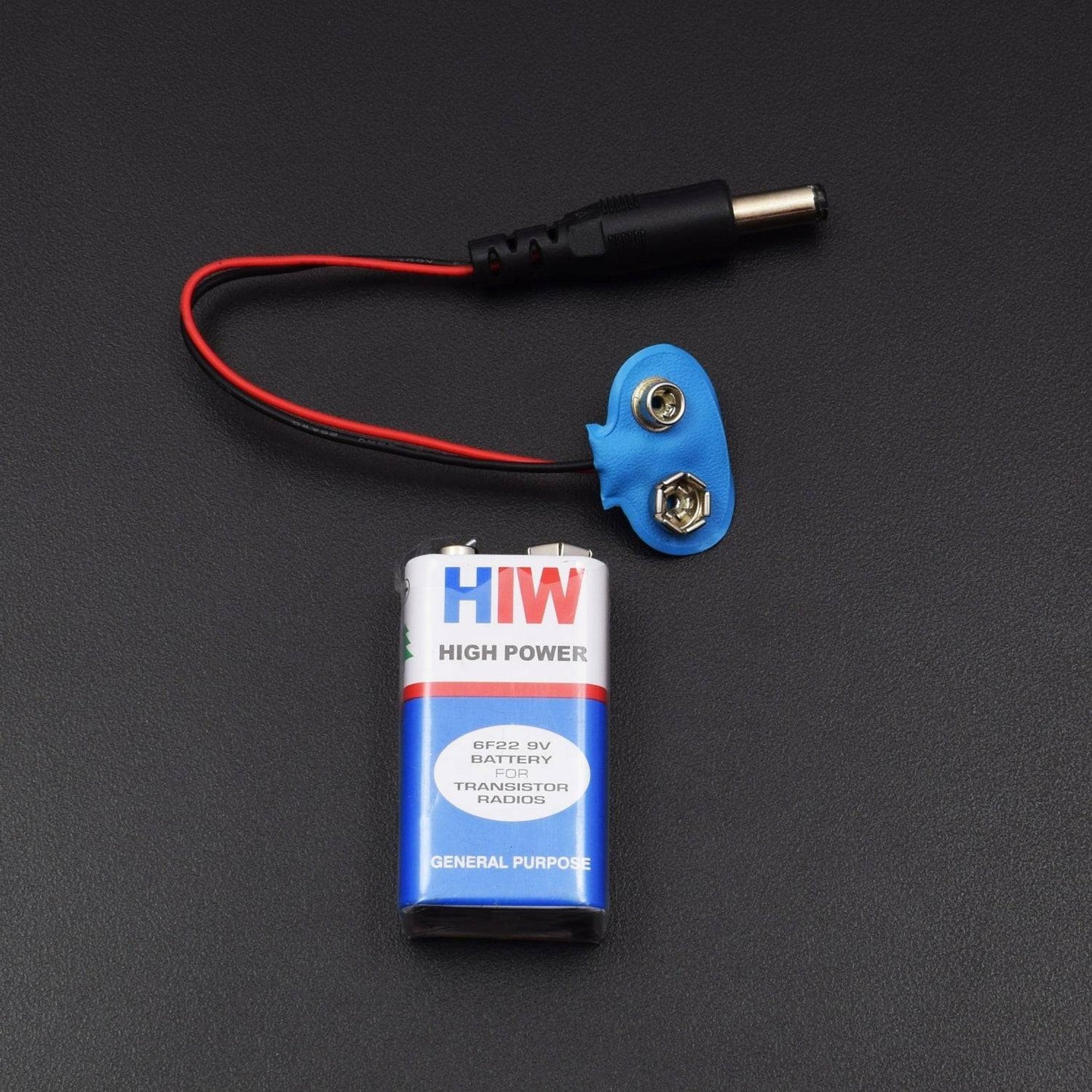
- 9v battery - 1
- Battery DC jack –1
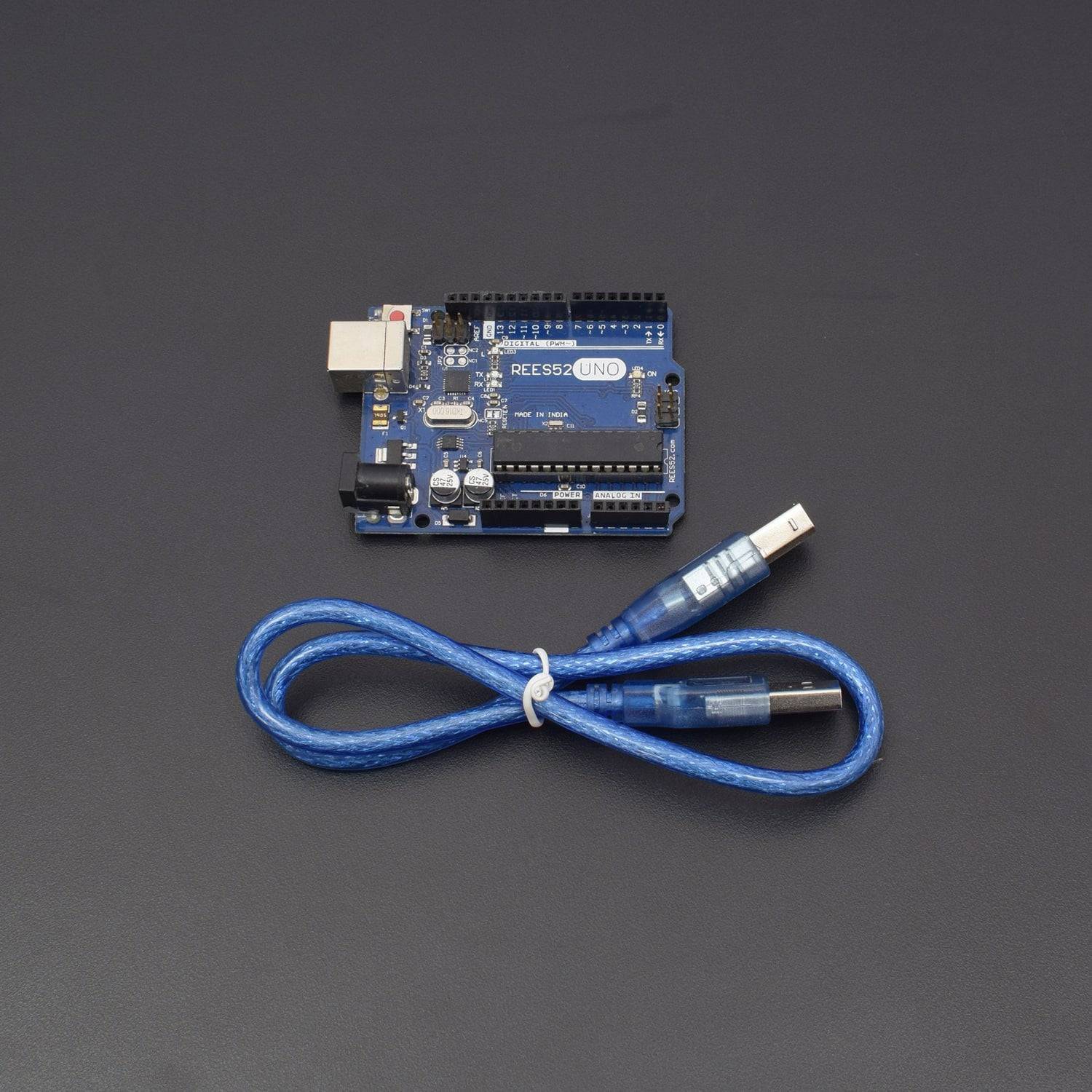
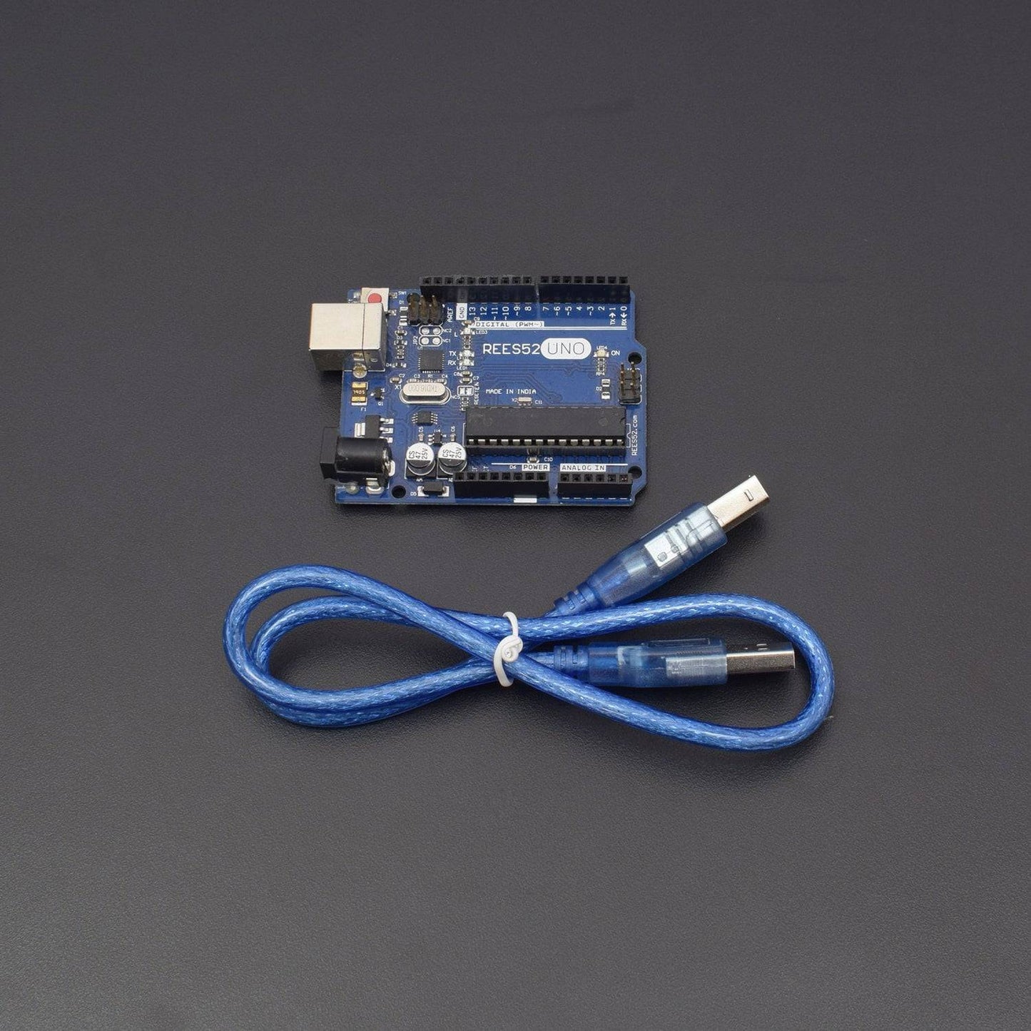
- Arduino uno with USB cable – 2
- NRF24L01 – 2
- Push button – 1
- Led – 2
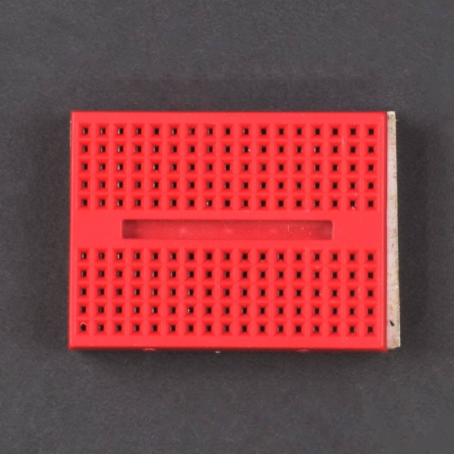
- Breadboard 170 points – 1
- Jumper wires male to female – 40 pieces
- Jumper wires male to male – 40 pieces
HARDWARE REQUIRED
- 9v battery - 1
- Battery DC jack –1
- Arduino uno with USB cable – 2
- NRF24L01 – 2
- Push button – 1
- Led – 2
- Breadboard 170 points – 1
- Jumper wires male to female – 40 pieces
- Jumper wires male to male – 40 pieces
SOFTWARE REQUIRED
Arduino IDE 1.8.5 (programmable platform for Arduino)
Click To Download: https://www.arduino.cc/en/Main/Software


SPECIFICATIONS
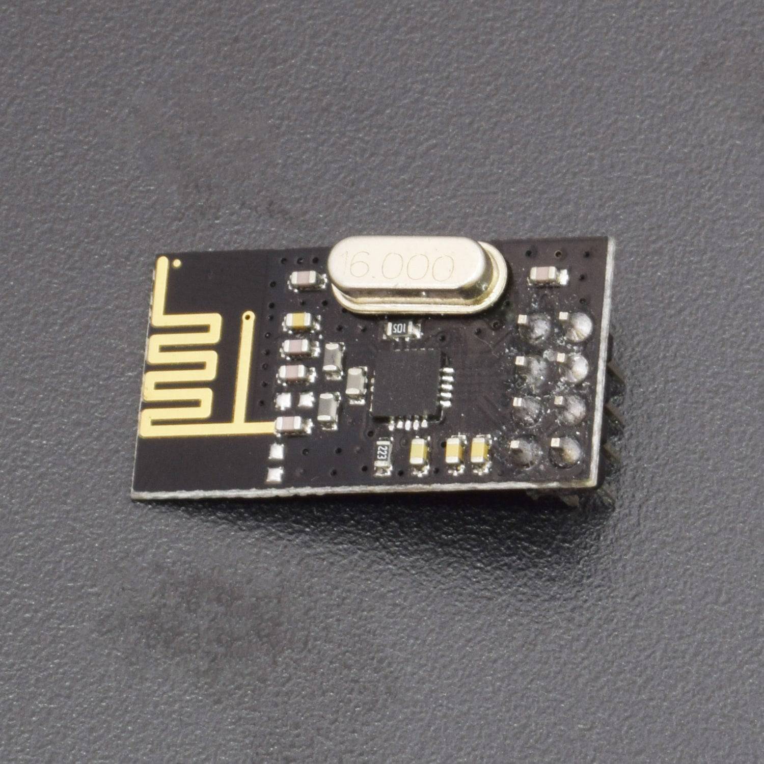
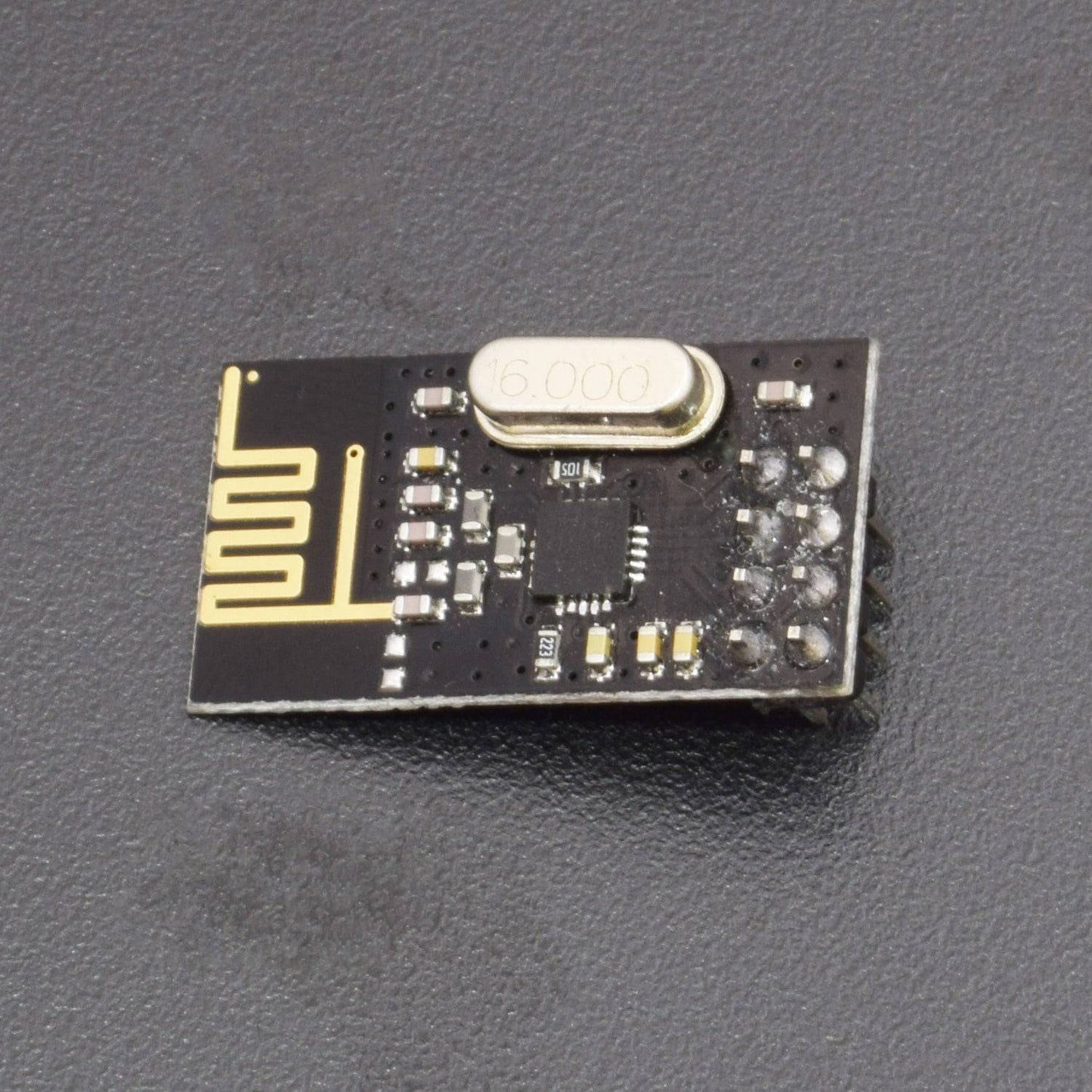
NRF24L01

NRF24L01+ is a single-chip radio transceiver for the worldwide 2.4-2.5 GHz ISM band. The radio transmitters and receivers include frequency generator, enhanced Shock Burst mode controller, power amplifier, crystal oscillator modulator and demodulator. You can select the output power channel and protocol by setting through the SPI port. The current consumption for the nRF24L01+ is extremely low - under the transmitter mode, when the transmitting power is 0dBm, the current consumption is only 11.3mA; under the receiving mode, it is 13.5mA; under the power down and idle mode, the consumption is even lower. As for application, it's widely used in many devices such as wireless mouse and keyboard, game handle, remote control set, industry sensor,toys, etc.
The pin functions of NRF24L01 are as shown:
Pin |
Name |
Description |
1 |
GND |
Ground (0V) |
2 |
VCC |
Power Supply (3.3V) |
3 |
CE |
Mode Enable Activates RX or TX mode |
4 |
CSN |
Chip Select |
5 |
SCK |
Serial Clock |
6 |
MOSI |
Master Output, Slave Input |
7 |
MISO |
Master Input, Slave Output |
8 |
IRQ |
Interrupt Request. Under wireless communication, MCU communicates with NRF24L01 by IRQ |
The nRF24L01 is a highly integrated, ultra-low power (ULP) 2Mbps RF transceiver IC for the 2.4GHz ISM (Industrial, Scientific and Medical) band. With peak RX/TX currents lower than 14mA, a sub μA power down mode, advanced power management, and a 1.9 to 3.6V supply range, the nRF24L01 provides a true ULP solution enabling months to years of battery lifetime when running on coin cells or AA/AAA batteries
- Voltage: 3-3.6V (recommended 3.3V) V
- Maximum output power: +20dBm
- Emission mode current(peak): 115mA
- Receive Mode Current(peak): 45mA
- Power-down mode current: 4.2uA
LED


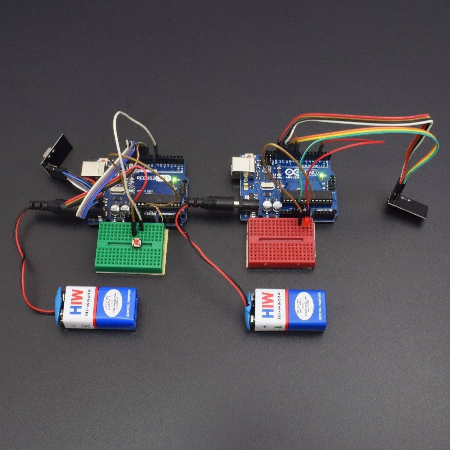
CIRCUIT CONNECTION
TRANSMITTER


RECEIVER
Connect the following pins to your Arduino: as shown in figure

- Pin 9 - CE
- Pin 10 - CS(N)
- Pin 11 - MOSI
- Pin 12 - MISO
- Pin 13 - SCK
- 3.3v - VCC
- GND - GND
- On the Receiver Pin 3 - LED
- On the Transmitter Pin 7 – Button
Same connection for receiver and transmitter and you can use any Arduino board
CODE
For coding Arduino first we need some library files so follow the steps given below:
- Download the ZIP file from this linkhttps://drive.google.com/open?id=1uUkFgECfYC1rVOSlrhtzfWQvA3czysji)
- Unpack the ZIP file.
- Go to Arduino library folder
- And paste both the folders named “nFR24L01" and "RF24" into it.
- Now, program the Arduino receiver and transmitter
Code for Receiver
Code for Transmitter
WORKING
This is the last step after completing the circuit and coding part we can easily test it by switching "ON" and "OFF".
When the switch is "ON" on transmitter side connected to pin 7 of Arduino then led glows on the receiver’s side connected to pin 3 of Arduino The video shows the output of this project.