


vendor-unknown
Turn off and on the fan by touching the switch - KT964
Turn off and on the fan by touching the switch - KT964
SKU:KT964
1000 in stock
Couldn't load pickup availability
- For Bulk Order Click Here
- Need Customer Support?
- Free Delivery Above 999/-
For refund/return/replacement, call us at +91 95995 94520 , +91 95991 22209 or mail us at support@rees52.com
Delivery Time
Delivery Time
- Delivery time with the Express Shipping option is 2-3 working days, and with the Standard Shipping option is 5-6 working days. It varies based on location, reliant on courier services.
- Delivery time if the order item is on Preorder Status is 15-20 working days.
COD (Cash on Delivery)
COD (Cash on Delivery)
- For COD you have to pay extra charges of Rs 350/- before the shipment. (We will share the company QR Code, UPI ID or Account details for the same)
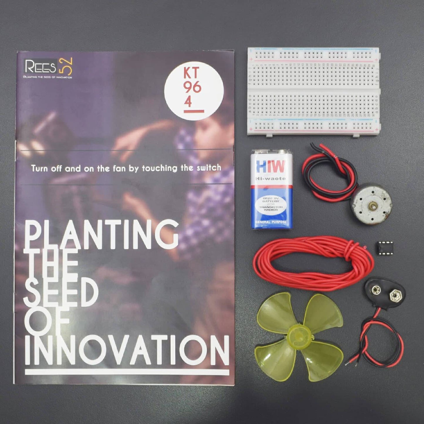
KIT INCLUDED:
- Breadboard 400 points – 1
- Fan or rotor – 1
- 9V Battery - 1
- Snapper – 1
- Single stand wire 2m - 1
- 555 timer ic – 1
- Non-Geared Dc motor – 1
HARDWARE REQUIRED
- Breadboard 400 points – 1
- Fan or rotor – 1
- 9V Battery - 1
- Snapper – 1
- Single stand wire 2m - 1
- 555 timer ic – 1
- Non-Geared Dc motor – 1
PIN DESCRIPTION
555 TIMER IC

Pin |
Name |
Purpose |
1 |
GND |
Ground reference voltage, low level (0 V) |
2 |
TRIG |
The OUT pin goes high and a timing interval starts when this input falls below 1/2 of CTRL voltage (which is typically 1/3 Vcc, CTRL being 2/3 Vcc by default if CTRL is left open). In other words, OUT is high as long as the trigger low. Output of the timer totally depends upon the amplitude of the external trigger voltage applied to this pin. |
3 |
OUT |
This output is driven to approximately 1.7 V below +Vcc, or to GND. |
4 |
RESET |
A timing interval may be reset by driving this input to GND, but the timing does not begin again until RESET rises above approximately 0.7 volts. Overrides TRIG which overrides threshold. |
5 |
CTRL |
Provides “control” access to the internal voltage divider (by default, 2/3 Vcc). |
6 |
THR |
The timing (OUT high) interval ends when the voltage at threshold is greater than that at CTRL (2/3 Vcc if CTRL is open). |
7 |
DIS |
Open collector output which may discharge a capacitor between intervals. In phase with output. |
8 |
Vcc |
Positive supply voltage, which is usually between 3 and 15 V depending on the variation. |
CIRCUIT DESCRIPTION

- Pin 1 of 555 TIMER IC to negative rail of BREADBAORD
- pin 8 of of 555 TIMER IC positive rail of BREADBOARD
- connect pin 4 of 555 TIMER IC to pin 8 of 555 TIMER IC
- connect two steel metal pin plate at pin 1 and 2 of 555 TIMER IC
- connect two steel metal pin plate at pin 6 and 8 of 555 TIMER IC
- connect dc motor one point at pin 1 of 555 TIMER IC and another point at pin 3 of 555 TIMER IC
WORKING
- When we touch the lower steel pins, motor will turn on and started rotating.

%201.jpg)
- When we touch the upper steel pins, motor will turn off.

%202.jpg)