


vendor-unknown
Turn LED On/Off using Light Blocking Sensor - KT657
Turn LED On/Off using Light Blocking Sensor - KT657
SKU:KT657
1000 in stock
Couldn't load pickup availability
- For Bulk Order Click Here
- Need Customer Support?
- Free Delivery Above 999/-
Note: In case you receive a damaged or faulty product, please return it in the original box with all foam and packaging. Returns will not be accepted if further damage occurs due to improper packing.
If you order a product that is currently in Preorder, and the price of that item increases in the future, you will be required to pay the difference in price.
For refund/return/replacement, call us at +91 95995 94520 or email us at support@rees52.com
Delivery Time
Delivery Time
- Delivery time with the Express Shipping option is 2-3 working days, and with the Standard Shipping option is 5-6 working days. It varies based on location, reliant on courier services.
- Delivery time if the order item is on Preorder Status is 15-20 working days.
COD (Cash on Delivery)
COD (Cash on Delivery)
- For COD you have to pay extra charges of Rs 350/- before the shipment. (We will share the company QR Code, UPI ID or Account details for the same)
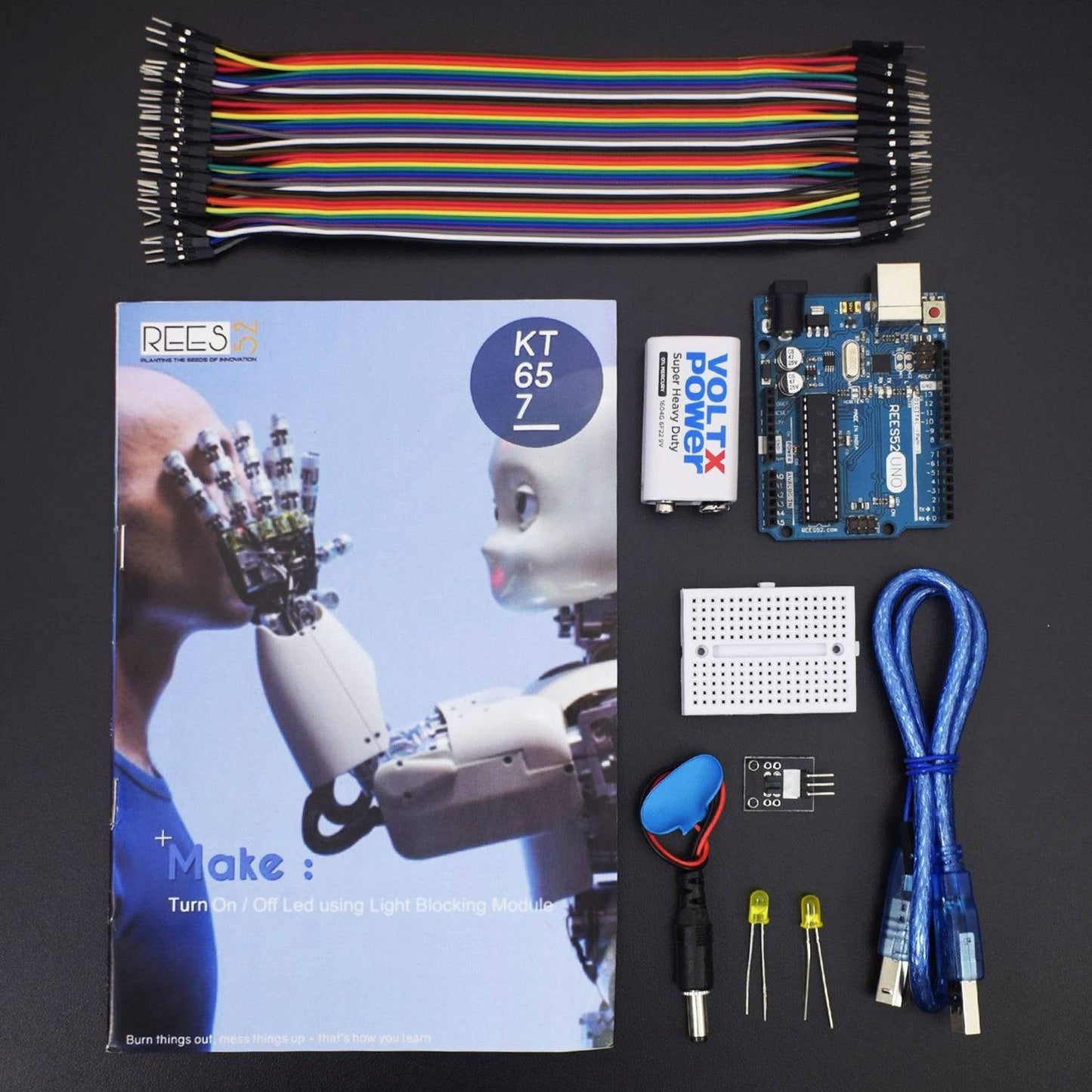
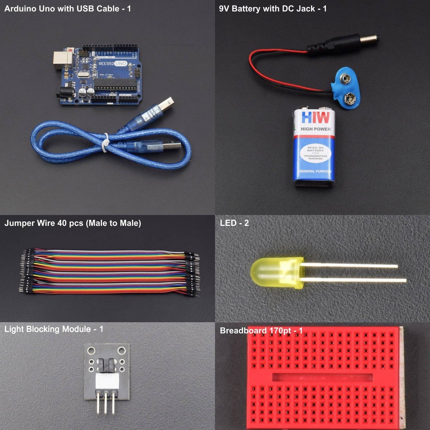

Hardware Required
- Arduino Uno With USB Cable - 1
- Light Blocking Module - 1
- Led - 2
- 9V Battery - 1
- Snapper With DC Jack - 1
- Bread Board 170 Point - 1
- Jumper Wire (male to male) - 40 pcs
Introduction
In this project, we will know about the basic functionality of Light Blocking Sensor and also turn the LED On/Off using the sensor.
HARDWARE REQUIRED
- Arduino Uno With USB Cable - 1
- Light Blocking Module - 1
- Led - 2
- 9V Battery - 1
- Snapper With DC Jack - 1
- Bread Board 170 Point - 1
- Jumper Wire (male to male) - 40 pcs
SOFTWARE REQUIRED
Arduino IDE 1.8.5 (programmable platform for Arduino)
Click To Download: https://www.arduino.cc/en/Main/Software
SPECIFICATIONS
Light Blocking Module
This sensor is widely used in motor speed detection, pulse count, the position limit, etc. The DO output interface can be directly connected to a micro-controller IO port, if there is a block detection sensor, such as the speed of the motor encoder can detect. DO modules can be connected to the relay, limit switch, and other functions, it can also with the active buzzer module, compose alarm.
- Using imported groove optical coupling sensor, width 5mm.
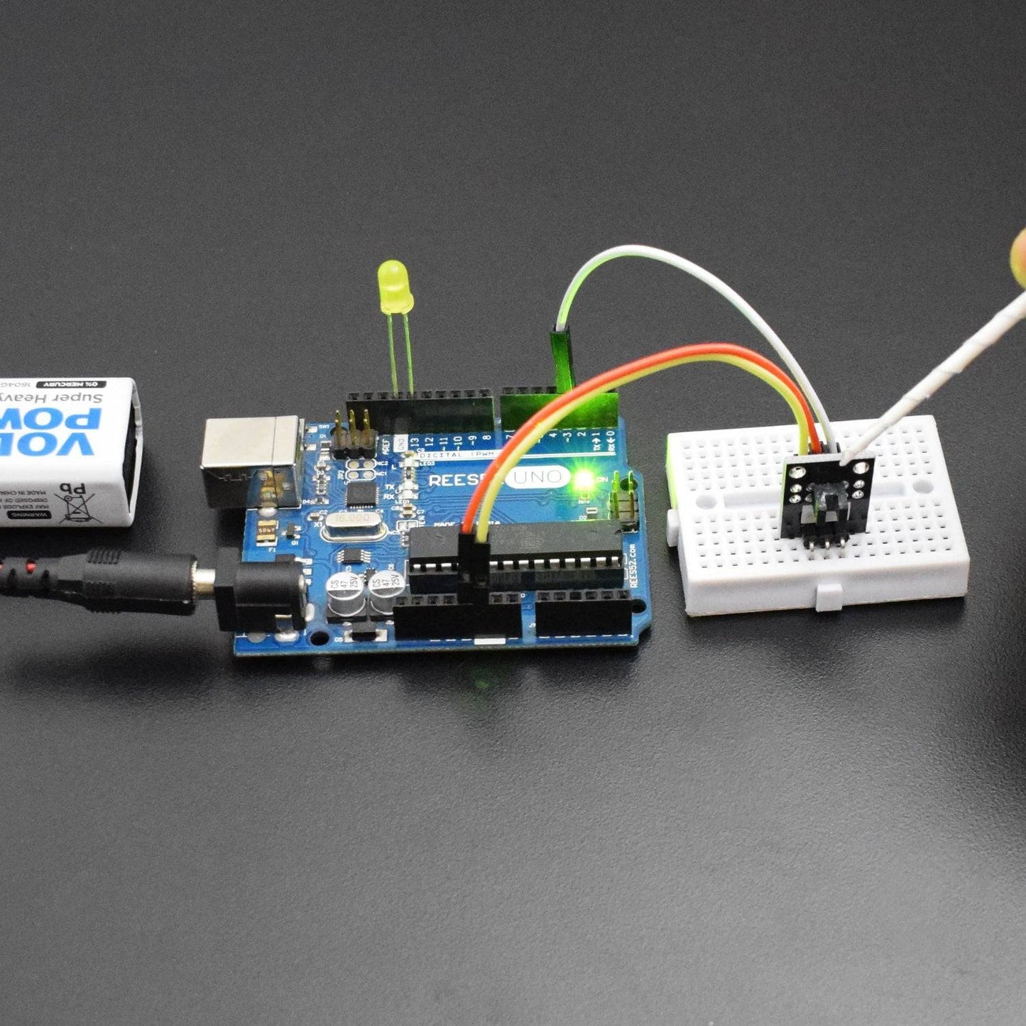
- It has the output state light, if output high level, the lights are off. If output low level, it stays on.
- If it covered, it will output a high level; otherwise low level.
- Good signal & waveform, with the strong driving ability for more than 15mA.
- The working voltage of 3.3V to 5V
- Output: digital switch output (0 and 1)
- Equipped with a fixed bolt hole, easily install.
- Use the LM393 wide voltage comparer

Arduino Uno

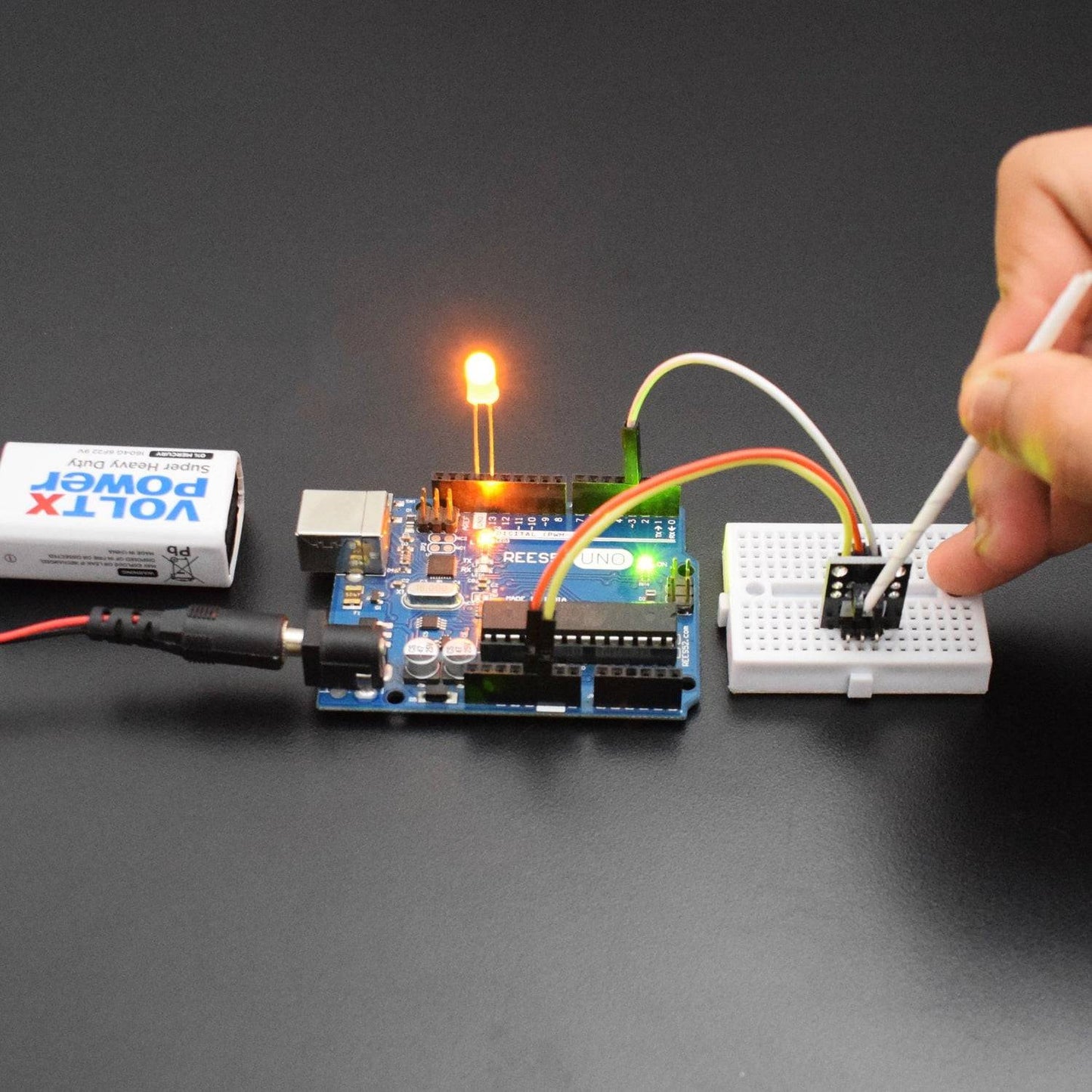
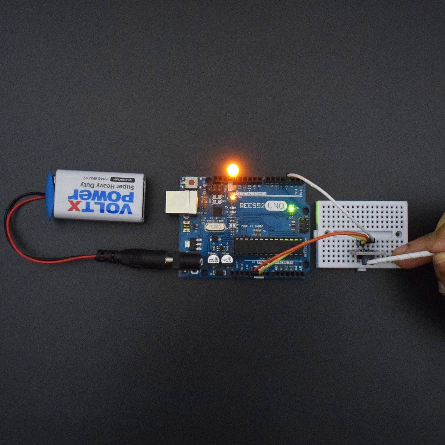
CIRCUIT CONNECTION
- Attach LED and Light Blocking Sensor on the Breadboard.
- Connect the negative terminal of LED with GND of Arduino Uno.
- Connect the positive terminal of LED with Digital Pin 13 of Arduino Uno.
- Connect VCC of Light Blocking Sensor with Pin 5V of Arduino Uno.
- Connect GND of Light Blocking Sensor with GND of Arduino Uno.
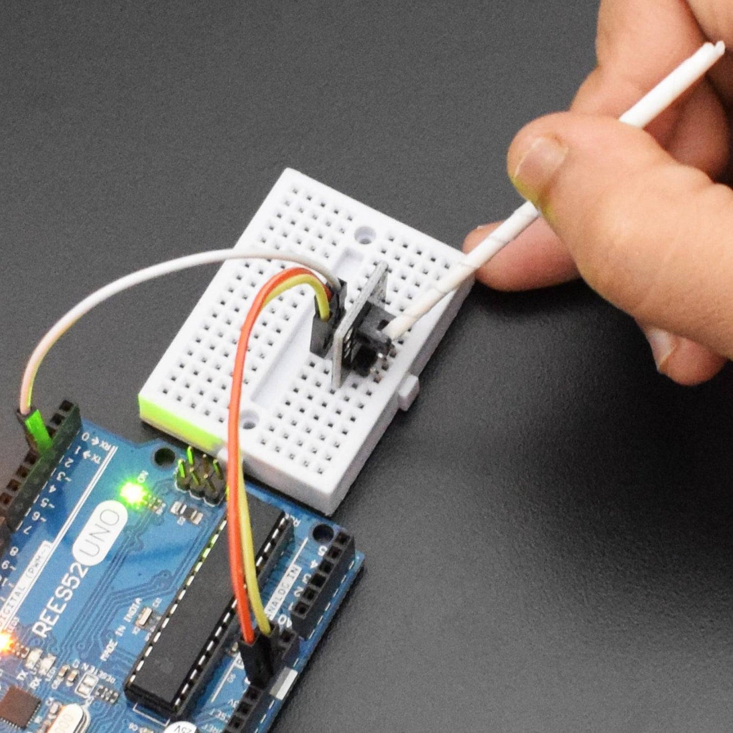
- Connect Pin Signal of Light Blocking Sensor with Digital Pin 3 of Arduino Uno.

CODE
https://drive.google.com/open?id=1jHCAusgsNebXamoNax8uym-j_2AjPxTZ
WORKING
Welcome to the Arduino Based Project which consists of Light blocking Sensor Module. The basic functionality of this sensor is described here. It is transmission type photosensor that integrates optical receiving and transmitting elements in a single package. Since the method involves light blocking commonly named photo interrupter. A long life infrared photodiodes are applied for output while a single phototransistor and photo IC are integrated on the other side for light detection. A Photoelectric Sensor consists of an Emitter for emitting light and a Receiver for receiving light. When emitted light is interrupted or reflected by the sensing object, it changes the amount of light that arrives at the Receiver. The Receiver detects this change and converts it to an electrical output.
Here, we are controlling an LED which turns on when Light Blocking Sensor is interrupted with some external component.
