


vendor-unknown
Testing TTP224 touch pad module using 16*2 LCD DISPLAY i2c module interfacing with arduino nano-KT925
Testing TTP224 touch pad module using 16*2 LCD DISPLAY i2c module interfacing with arduino nano-KT925
SKU:KT925
1000 in stock
Couldn't load pickup availability
- For Bulk Order Click Here
- Need Customer Support?
- Free Delivery Above 999/-
Note: In case you receive a damaged or faulty product, please return it in the original box with all foam and packaging. Returns will not be accepted if further damage occurs due to improper packing.
If you order a product that is currently in Preorder, and the price of that item increases in the future, you will be required to pay the difference in price.
For refund/return/replacement, call us at +91 95995 94520 or email us at support@rees52.com
Delivery Time
Delivery Time
- Delivery time with the Express Shipping option is 2-3 working days, and with the Standard Shipping option is 5-6 working days. It varies based on location, reliant on courier services.
- Delivery time if the order item is on Preorder Status is 15-20 working days.
COD (Cash on Delivery)
COD (Cash on Delivery)
- For COD you have to pay extra charges of Rs 350/- before the shipment. (We will share the company QR Code, UPI ID or Account details for the same)
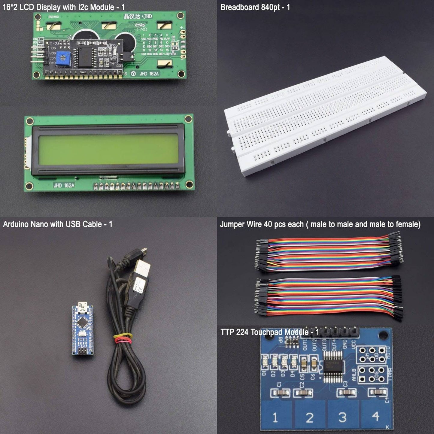
KIT INCLUDED:
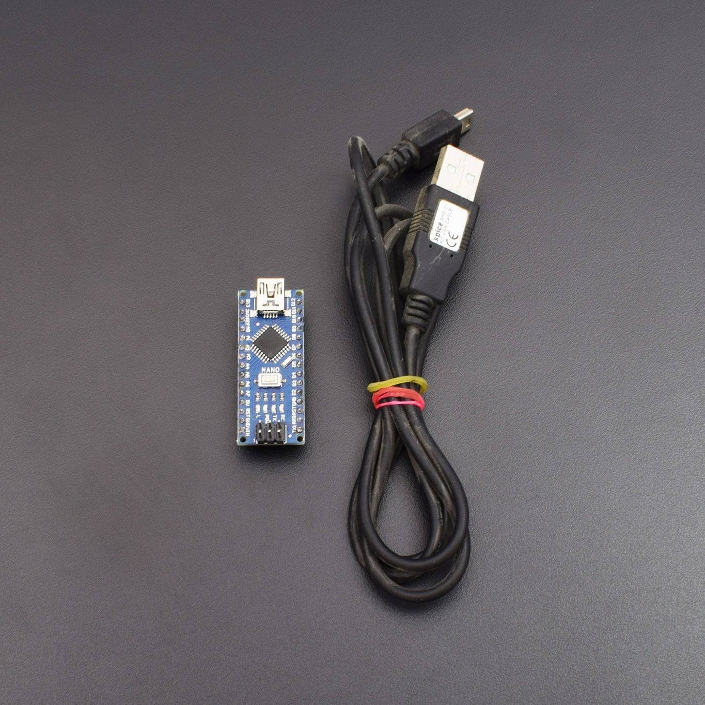
- Arduino Nano with USB Cable - 1
- TTP224B 4-channel capacitive module - 1
- Power bank-1(not included in kit)
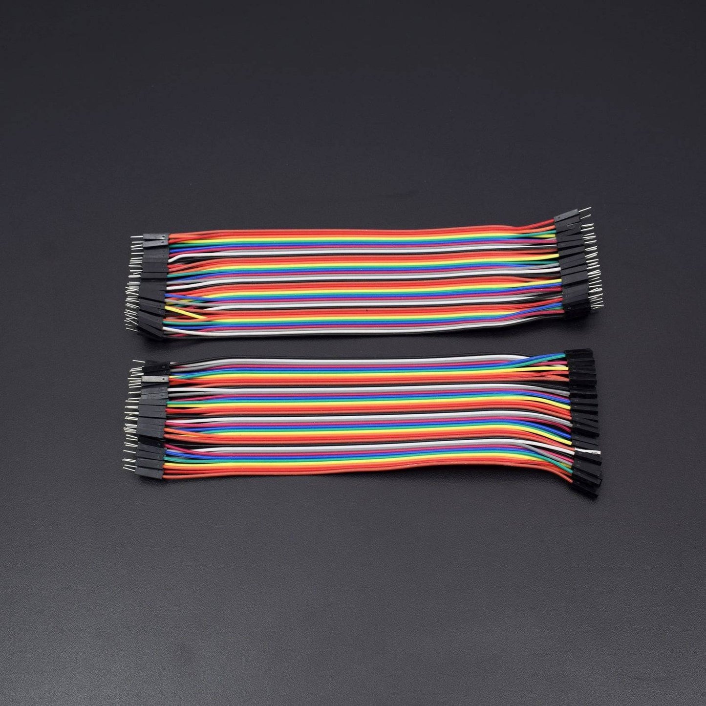
- Jumper wire male to female – 40 piece
- Jumper wire male to male – 40 piece
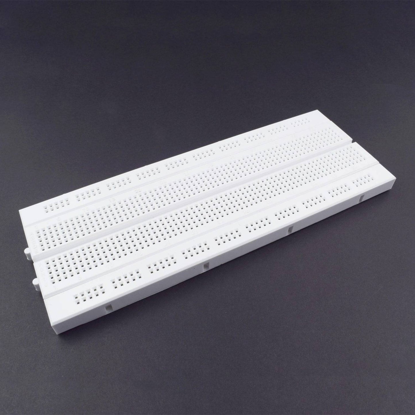
- Breadboard 840 points - 1
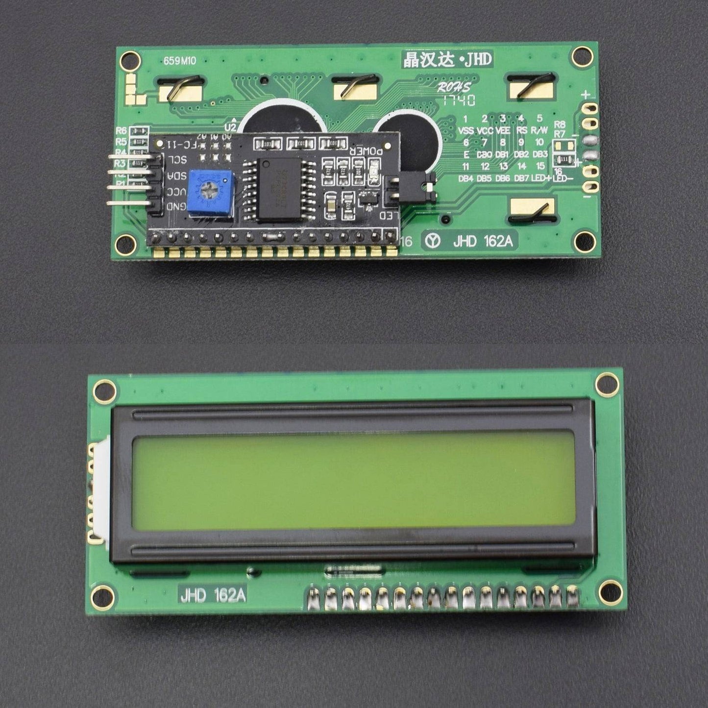
- 16*2 lcd with i2c module - 1
HARDWARE REQUIRED
- Arduino Nano with USB Cable - 1
- TTP224B 4-channel capacitive module - 1
- Power bank-1(not included in kit)
- Jumper wire male to female – 40 piece
- Jumper wire male to male – 40 piece
- Breadboard 840 points - 1
- 16*2 lcd with i2c module - 1
SOFTWARE REQUIRED
Arduino IDE 1.8.5 (programmable platform for Arduino)
Click To Download :https://www.arduino.cc/en/Main/Software

SPECIFICATIONS
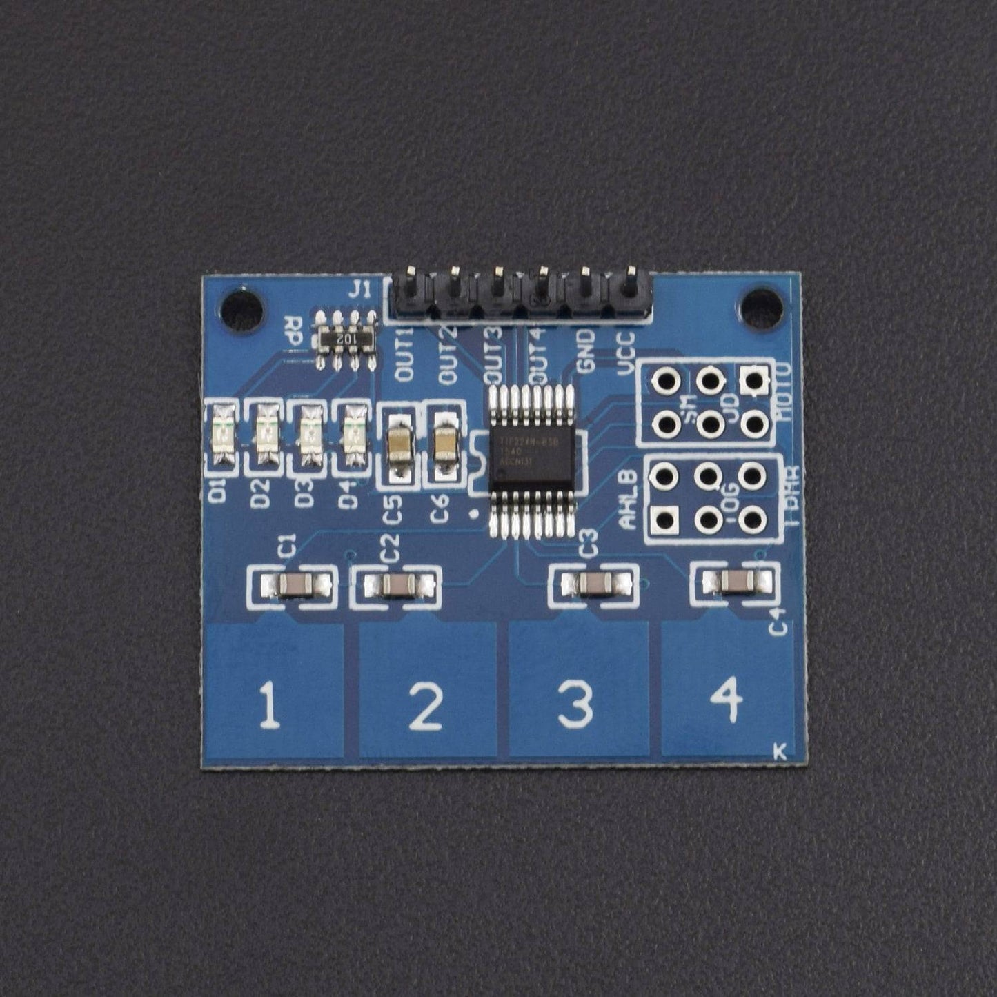
TTP224B 4-CHANNEL CAPACITIVE TOUCH MODULE
- On-board TTP224 capacitive touch 4 key induction IC
- On-board 4 road level indicator.
- Working voltage: 2 V to 5.5 V DC
- Adjustable output mode, key output mode, longest time and fast/low power output
- PCB board size: 35(mm) x29 (mm).
ARDUINO NANO
Arduino Pro Mini | |
Microcontroller |
ATmega168 |
Operating Voltage |
3.3V or 5V |
Input Voltage |
3.35 -12 V (3.3V model) or 5 - 12 V (5V model) |
Digital I/O Pins |
14 (of which 6 provide PWM output) |
Analog Input Pins |
8 |
DC Current per I/O Pin |
40 mA |
Flash Memory |
16 KB (of which 2 KB used by bootloader) |
SRAM |
1 KB |
EEPROM |
512 bytes |
Clock Speed |
8 MHz (3.3V model) or 16 MHz (5V model) |
PIN DESCRIPTION
TTP224B 4-CHANNEL CAPACITIVE TOUCH MODULE
VCC: 2V to 5.5V DC
GND: ground
OUT4: high/low output
OUT3: high/low output
OUT2: high/low output
OUT1: high/low output
ARDUINO NANO
RAW |
For supplying a raw (regulated) voltage to the board |
VCC |
The regulated 3.3 or 5 volt supply |
GND |
Ground pins |
RX |
Used to receive TTL serial data |
TX |
Used to transmit TTL serial data |
2 and 3 |
Digital I/O pins. These pins can also be configured to trigger an interrupt on a low value, a rising or falling edge, or a change in value |
3, 5, 6, 9, 10, and 11 |
Digital I/O pins. They can also be configured to provide 8-bit PWM output |
10, 11, 12 and 13 |
Digital I/O pins. They can also be configured as SPI pins; 10 - (SS), 11 - (MOSI), 12 - (MISO) and 13 - (SCK) |
A0 to A3 |
Analog input pins |
A4 and A5. |
Analog input pins. They can also be used as IIC pins; A4 - (SDA) and A5 – (SCL). |
A6 and A7 |
Analog input pins |
Reset |
The microcontroller can be reset by bringing this pin low |
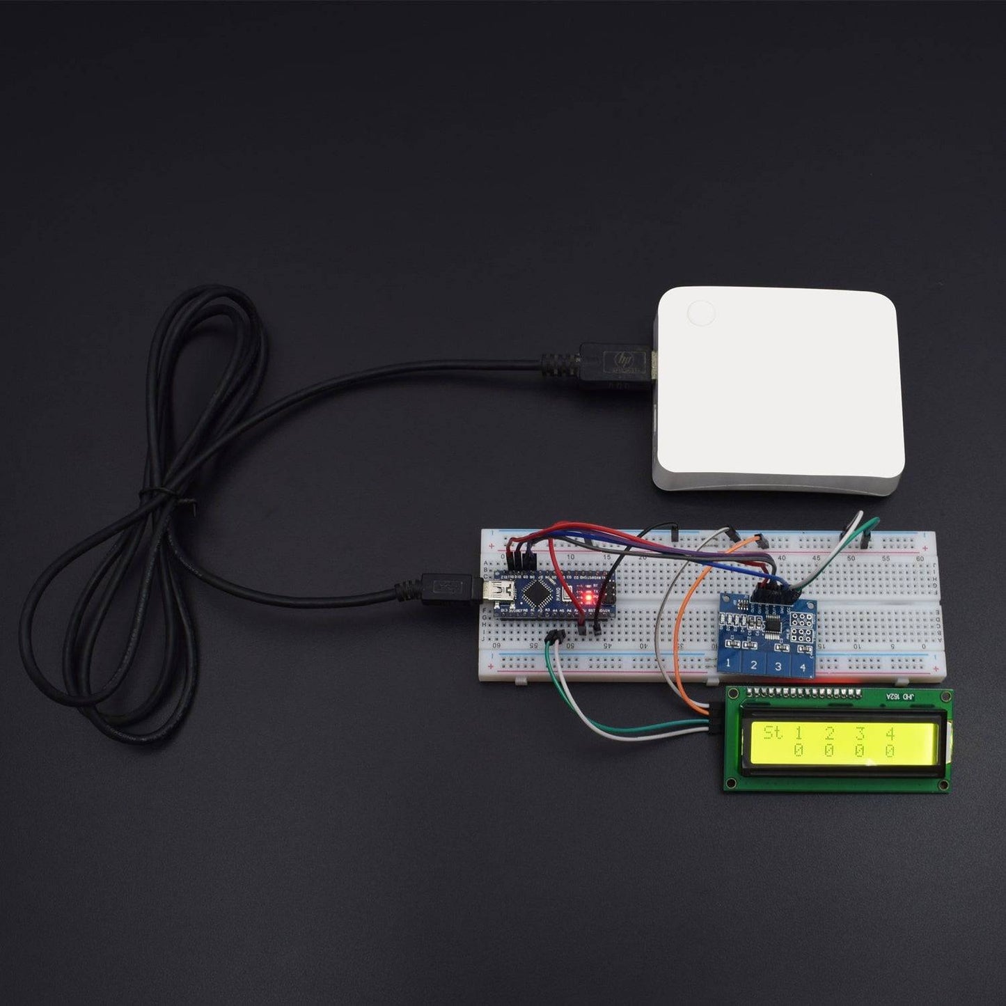
CIRCUIT CONNECTION
- Out1 of TTP224 to the Nano D11
- Out2 of TTP224 to the Nano D10
- Out3 of TTP224 to the Nano D9
- Out4 of TTP224 to the Nano D8
- Ground to the negative rail and Vcc to the positive rail
- I2C module Vcc to positive rail and ground to negative rail
- I2C module sda pin to Nano A4 and scl to A5

CODE
Click to see the code or copy the link:
WORKING
Upload the code and see the output.
