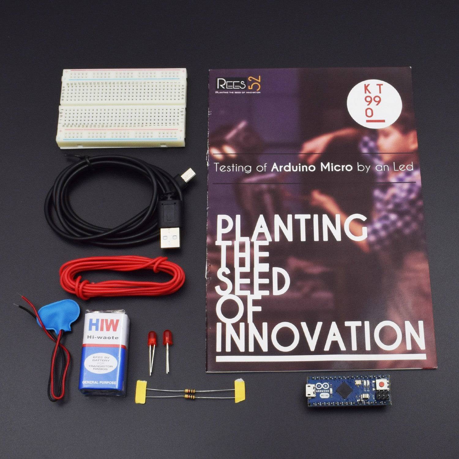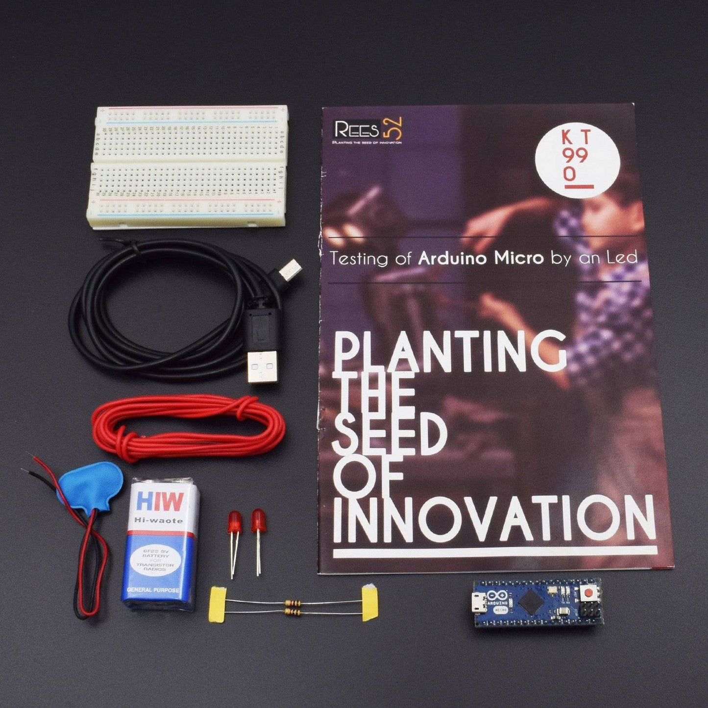

In this project, we are testing Arduino Micro by blinking a led.
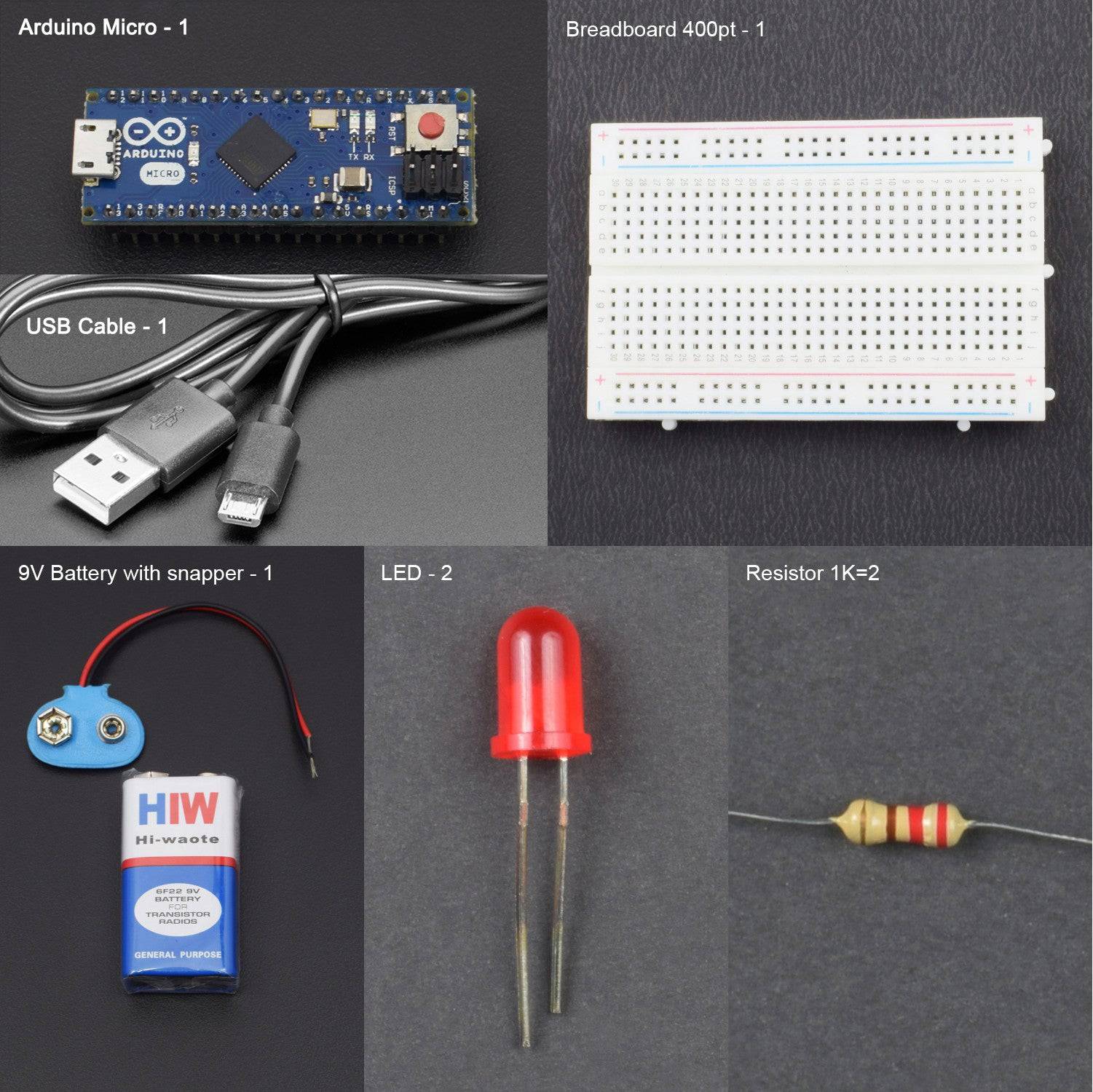
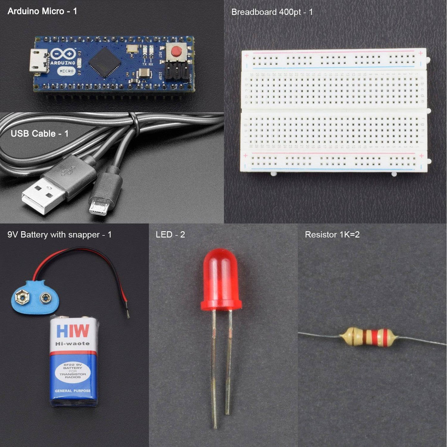
- Arduino micro - 1
- Arduino Micro USB cable - 1
- Breadboard 400 points - 1
- Single Stand Wires 2 mt - 1
- Led - 2
- Resistor (1k) - 2
- 9v battery-1
- Battery Snapper – 1
HARDWARE REQUIRED
- Arduino micro - 1
- Arduino Micro USB cable - 1
- Breadboard 400 points - 1
- Single Stand Wires 2 mt - 1
- Led - 2
- Resistor (1k) - 2
- 9v battery-1
- Battery Snapper – 1
SOFTWARE REQUIRED
Arduino IDE 1.8.5 (programmable platform for Arduino)
Click To Download: https://www.arduino.cc/en/Main/Software
SPECIFICATIONS
Arduino Micro

Led

CIRCUIT DESCRIPTION
- Make Positive and Negative rail on breadboard for making further connection.
- Connect Arduino Micro’s Digital pin 13 to 1k resistor’s terminal 1 and terminal 2 to negative terminal of led.(To check the terminal see the pin description of Led)
- Connect Led Positive point to positive rail on breadboard.
- Connect arduino micro’s 5v to Positive rail on breadboard.


CODE
Click to see the code or copy the link
https://drive.google.com/open?id=11kwj-SQOLDwPXwKcen8gz59mCr2QjXEd
OUTPUT
- In this arduino micro testing we connect 1k resistor and led with arduino micro after connecting all and upload the program
- Led will blink after every second.
- By change the delay we can change the blinking time.


