


vendor-unknown
Test a GY-9150 MPU-9150 3-Axis Electronic Compass Acceleration Gyroscope Module Interfacing with Arduino Uno - KT701
Test a GY-9150 MPU-9150 3-Axis Electronic Compass Acceleration Gyroscope Module Interfacing with Arduino Uno - KT701
SKU:KT701
1000 in stock
Couldn't load pickup availability
- For Bulk Order Click Here
- Need Customer Support?
- Free Delivery Above 999/-
Note: In case you receive a damaged or faulty product, please return it in the original box with all foam and packaging. Returns will not be accepted if further damage occurs due to improper packing.
If you order a product that is currently in Preorder, and the price of that item increases in the future, you will be required to pay the difference in price.
For refund/return/replacement, call us at +91 95995 94520 or email us at support@rees52.com
Delivery Time
Delivery Time
- Delivery time with the Express Shipping option is 2-3 working days, and with the Standard Shipping option is 5-6 working days. It varies based on location, reliant on courier services.
- Delivery time if the order item is on Preorder Status is 15-20 working days.
COD (Cash on Delivery)
COD (Cash on Delivery)
- For COD you have to pay extra charges of Rs 350/- before the shipment. (We will share the company QR Code, UPI ID or Account details for the same)
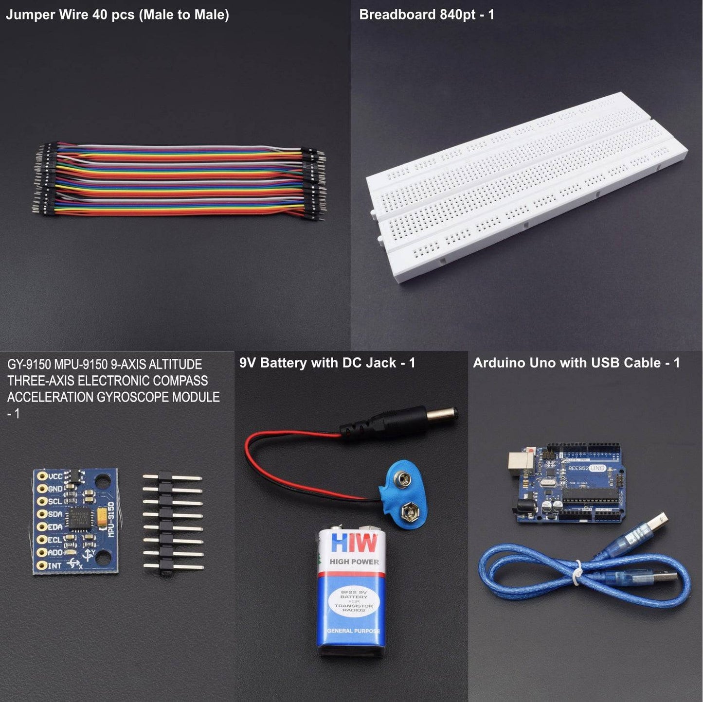

KIT INCLUDED:
- Jumper Wires (male to male) – 40 pieces
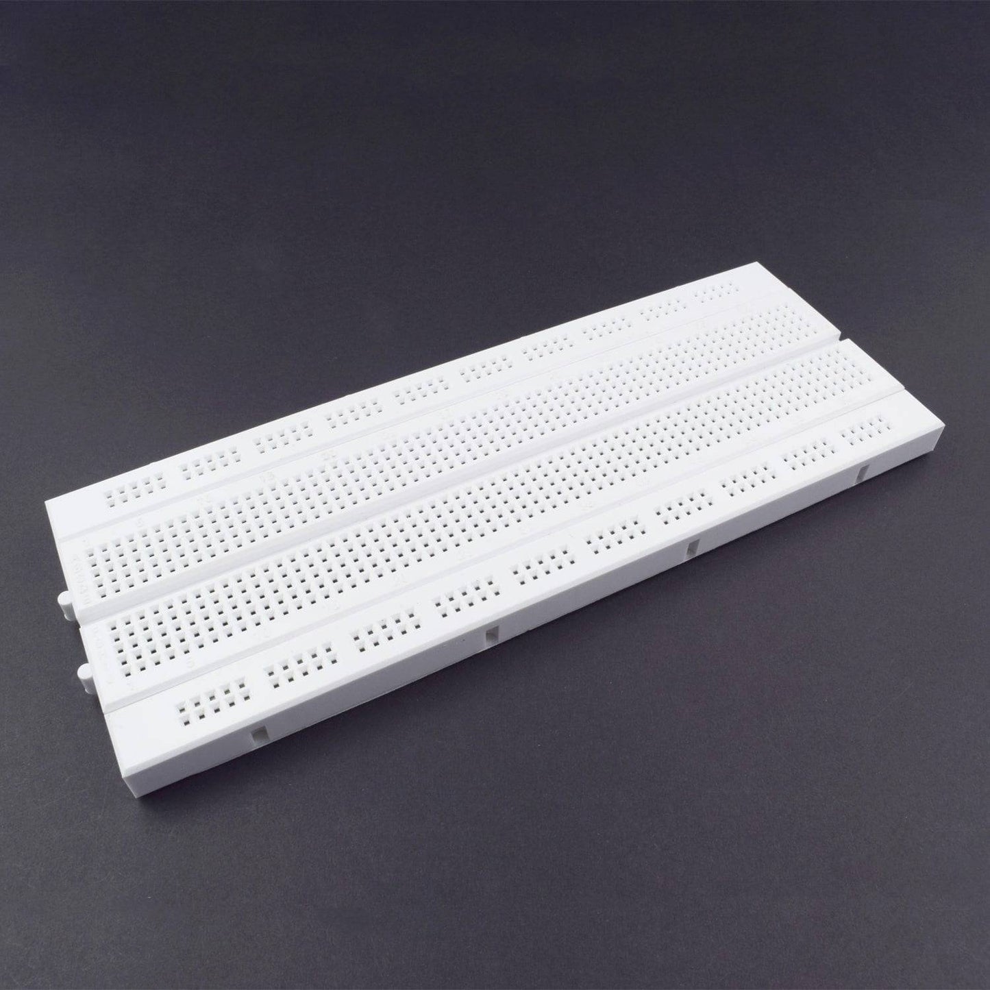
- Breadboard 840 points – 1
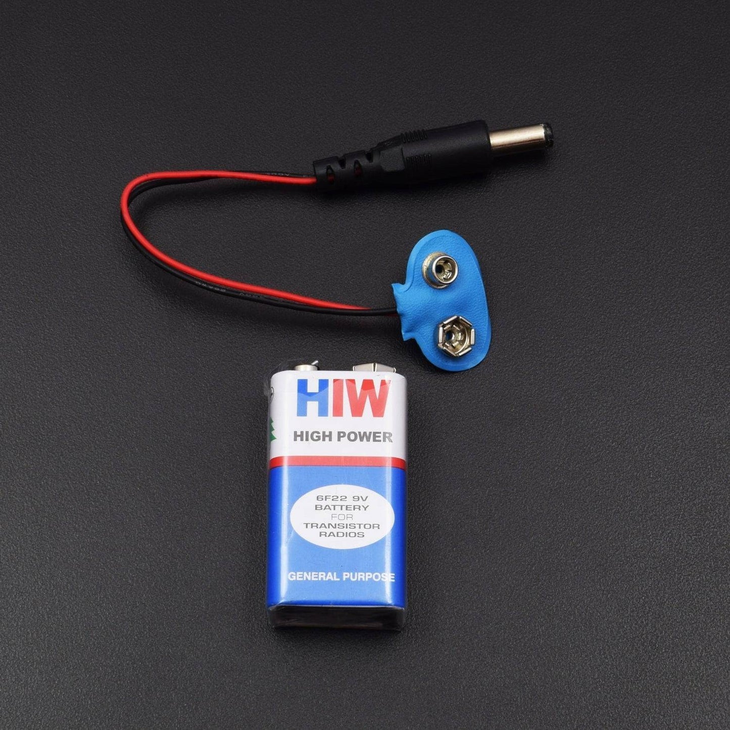
- 9V battery with DC Jack – 1
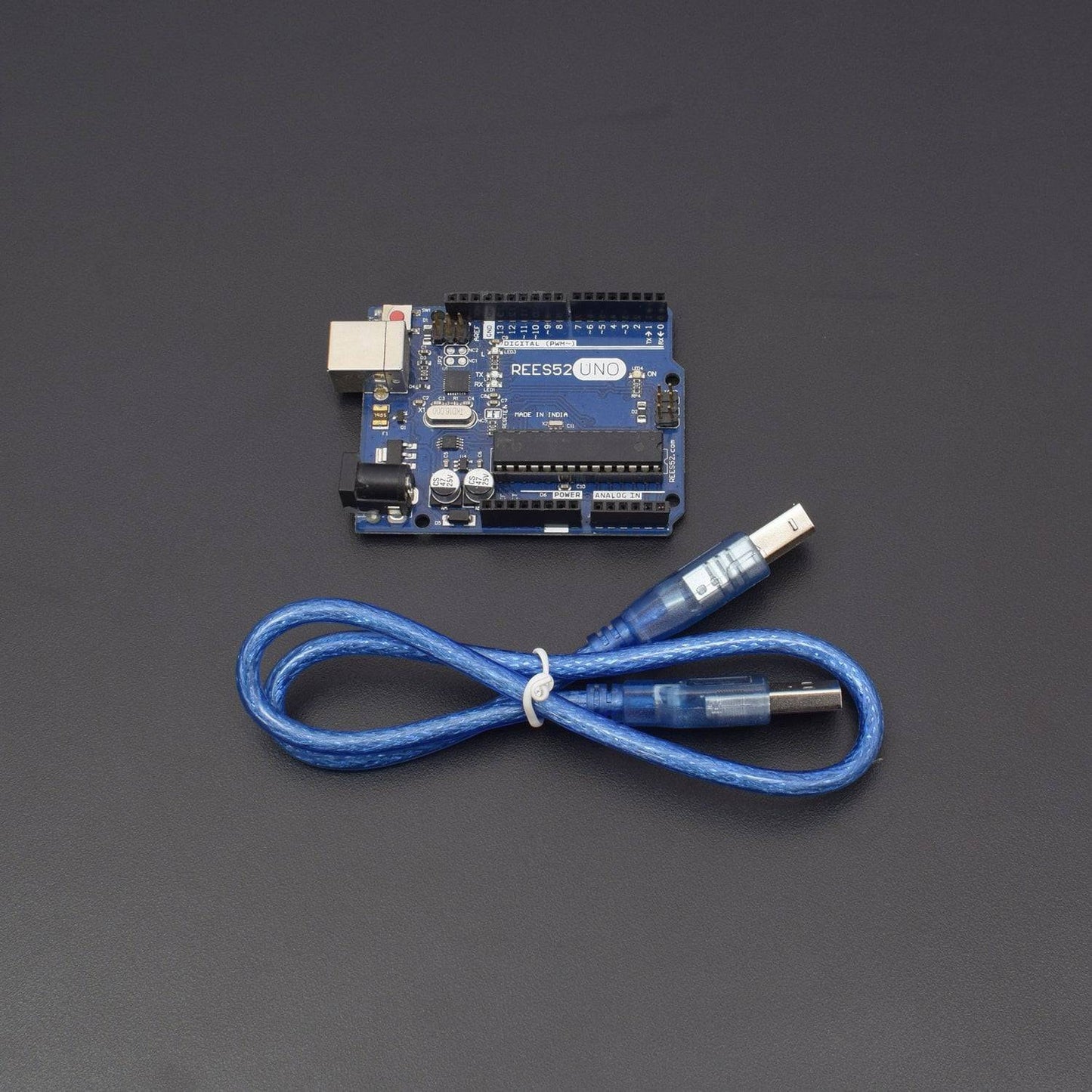
- Arduino Uno with USB cable – 1
- GY-9150 MPU-9150 9-Axis Altitude Three-Axis Electronic Compass Acceleration Gyroscope Module - 1
HARDWARE REQUIRED
- Jumper Wires (male to male) – 40 pieces
- Breadboard 840 points – 1
- 9V battery with DC Jack – 1
- Arduino Uno with USB cable – 1
- GY-9150 MPU-9150 9-Axis Altitude Three-Axis Electronic Compass Acceleration Gyroscope Module - 1
SOFTWARE REQUIRED
Arduino IDE 1.8.5 (programmable platform for Arduino)
Click To Download :https://www.arduino.cc/en/Main/Software

SPECIFICATIONS
GY-9150 MPU-9150 Three-Axis Acceleration Gyroscope Module
The MPU-9150 consists of a 9-axis Motion Fusion which combines both acceleration and rotational motion which helps in heading information into a single data stream for the application. Such technology integration provides a smaller footprint and has better cost advantages compared to discrete gyroscope, accelerometer, plus magnetometer solutions.
- It also inculcates a Digital Motion Processor (DMP) also known as hardware accelerator engine.
- The Accelerometer's scale can be set to ±2g, ±4g, ±6g, ±8g, or ±16g.
- The Gyroscope also supports ±250, ±500, and ±2000 °/s.
- Small in size
- MPU-9150 internal integration (three-axis gyroscope + tri-axial accelerometer + Tri-axis compass)
- Module Model: GY-9150, chip: MPU-9150
- Supply voltage: 3.3v-5v
- Communication: standard IIC communication protocol
- It also consists of in-built16 bit AD converter, 16-bit data output
- Tri-axis accelerometer with a programmable full scale range of ±2g, ±4g, ±8g and ±16g
- Tri-axis compass with a full scale range of ±1200µT
PIN DESCRIPTION
GY-9150 MPU-9150 Three-Axis Acceleration Gyroscope Module
S.NO |
NAME (Adruino) |
DESCRIPTION |
1 |
GND |
GND (It grounds the Input and completes the circuit) |
2 |
VCC |
3.3V (Recommended Voltage) |
3 |
SDA |
SDA (Serial Data Pin is used for I2C communication) |
4 |
SCL |
SCL (Serial Clock Pin is used for I2C serial clock) |
5 |
EDA |
Auxiliary I2C master serial data (It allows an external system processor to act as master and directly communicate to the external sensors connected to the auxiliary I2C bus pins) |
6 |
ECL |
Auxiliary I2C Master serial clock (It allows an external system processor to act as master and directly communicate to the external sensors connected to the auxiliary I2C bus pins) |
7 |
ADO |
I2C Slave Address LSB (The LSB of the of the I2C slave address is set by pin 9) |
8 |
INT |
Interrupt digital output |

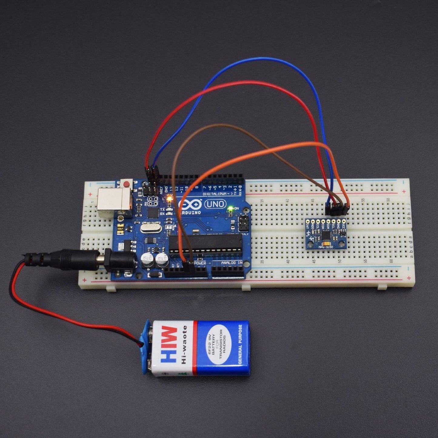
CIRCUIT CONNECTION
- The GND of Arduino is being connected to the GND pin of the MPU9150.
- The SDA (Serial Data) pin of Arduino is being connected with the SDA pin used inMPU9150 for I2C bidirectional communication.
- The Arduino UNO can be powered by the 9V battery which helps in executing the entire further process.
- The SCL (Serial Clock) pin of Arduino is being connected with the SCL pin used inMPU9150 for I2C Serial Clock.
- The VCC of the MPU9150 is being connected to the 3.3V as per recommended as higher voltage can damage it.
- The EDA is the Auxiliary I2C master serial data which allows an external system processor to act as master and directly communicate to the external sensors connected to the auxiliary I2C bus pins. But it is not used in this particular circuit.
- The ECL is the Auxiliary I2C Master serial clock which allows an external system processor to act as master and directly communicate to the external sensors connected to the auxiliary I2C bus pins. But it is not used in this particular circuit.
- The AD0 Pin is the I2C Slave Address LSB. The LSB (Least Significant Byte) of the of the I2C slave address is set by Arduino Pin (Mostly Pin 9). But it is not used in this particular circuit.
- The INT Pin is the Interrupt Pin. It is for the Digital Output. But it is not used in this particular circuit.

CODE
Click to see code here: https://docs.google.com/document/d/e/2PACX-1vTzGZQNgKtezfRIQyzaVrBBhjvooeOF2cX3ay_qb4rjkMZHA4787biYqskH2uBeaFt3O_gWwmFiJLcY/pub?embedded=true
LIBRARIES REQUIRED
Install the Libraries:
- I2C.h

- MPU6050.h

WORKING
This particular Arduino based project consists of a 3-axis accelerometer, 3-Axis gyroscope, 3-Axis magnetometer and a Digital Motion Processor which helps in enabling Motion Interfacing. The MPU-9150 is also designed to interface with multiple non-inertial digital sensors, such as pressure sensors, on its auxiliary I2C port to produce a 10-Axis sensor fusion output.
The MPU-9150 is a System in Package (SiP) which combines two chips: The MPU-6050, which contains a 3-axis gyroscope, 3-axis accelerometer, and an onboard Digital Motion Processor (DMP) capable of processing complex MotionFusion algorithms; and the AK8975, a 3-axis digital compass. The device has integrated 6-axis MotionFusion algorithms which accesses all internal sensors to gather a full set of sensor data. It also supports a variety of advanced motion-based applications entirely on-chip. The MPU-9150 enables low-power Motion Processing in portable applications with reduced processing requirements for the system processor.
Output:

Block Diagram:
