


vendor-unknown
Test a 16*2 LCD display with I2C module interfacing with arduino uno - KT822
Test a 16*2 LCD display with I2C module interfacing with arduino uno - KT822
SKU:KT822
1000 in stock
Couldn't load pickup availability
- For Bulk Order Click Here
- Need Customer Support?
- Free Delivery Above 999/-
Note: In case you receive a damaged or faulty product, please return it in the original box with all foam and packaging. Returns will not be accepted if further damage occurs due to improper packing.
If you order a product that is currently in Preorder, and the price of that item increases in the future, you will be required to pay the difference in price.
For refund/return/replacement, call us at +91 95995 94520 or email us at support@rees52.com
Delivery Time
Delivery Time
- Delivery time with the Express Shipping option is 2-3 working days, and with the Standard Shipping option is 5-6 working days. It varies based on location, reliant on courier services.
- Delivery time if the order item is on Preorder Status is 15-20 working days.
COD (Cash on Delivery)
COD (Cash on Delivery)
- For COD you have to pay extra charges of Rs 350/- before the shipment. (We will share the company QR Code, UPI ID or Account details for the same)


KIT INCLUDES:
- 16*2 i2c DISPLAY - 1
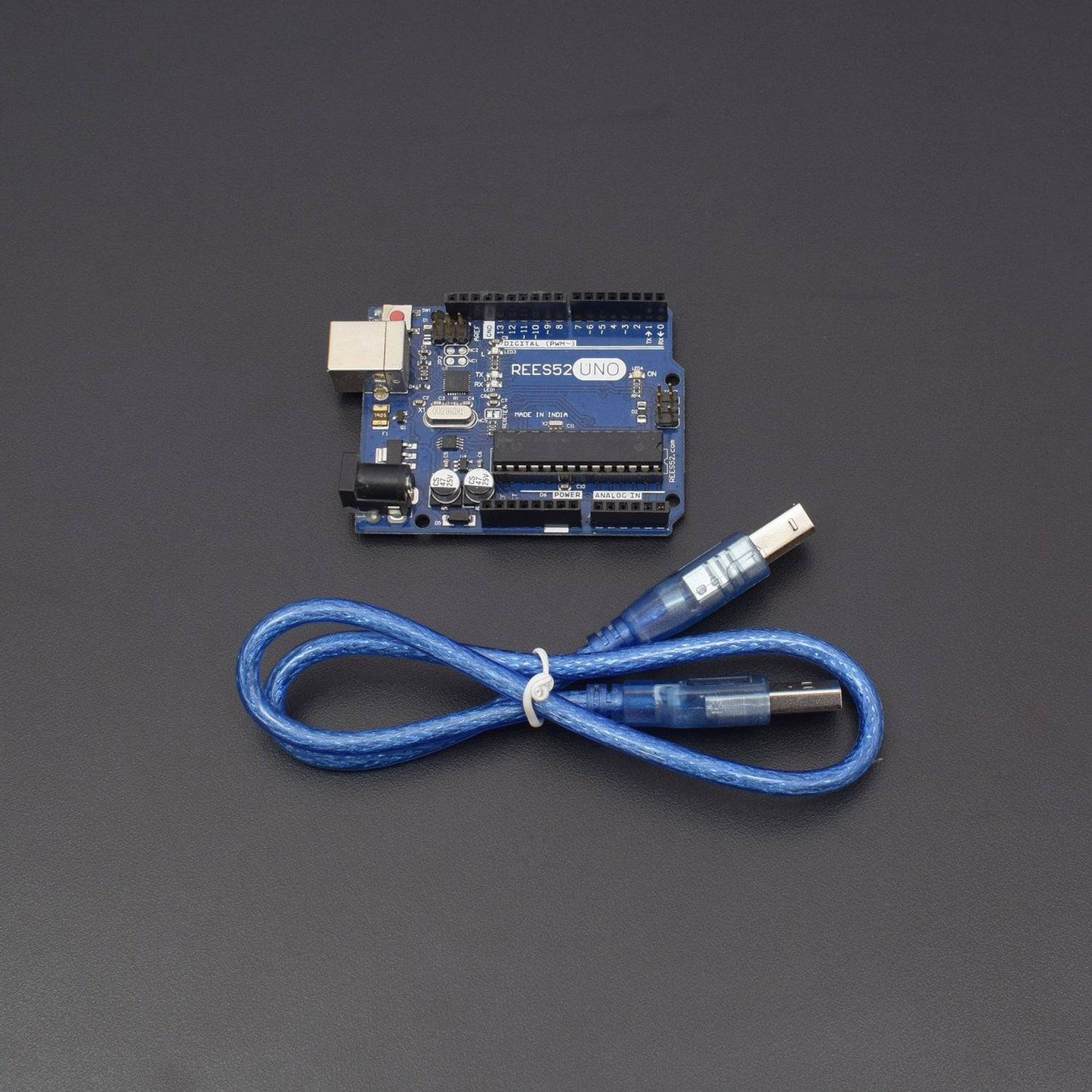
- Arduino uno with USB cable - 1
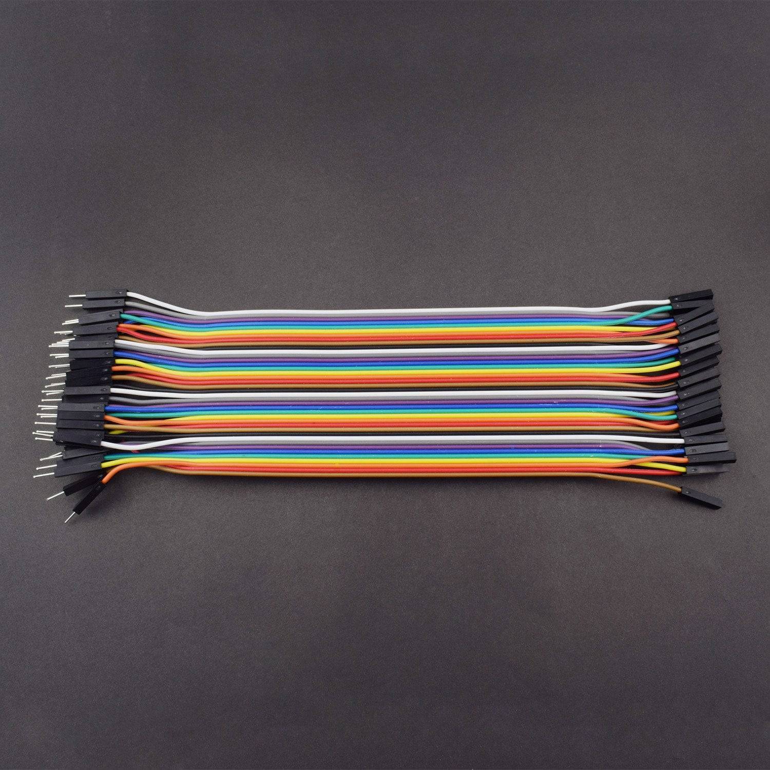
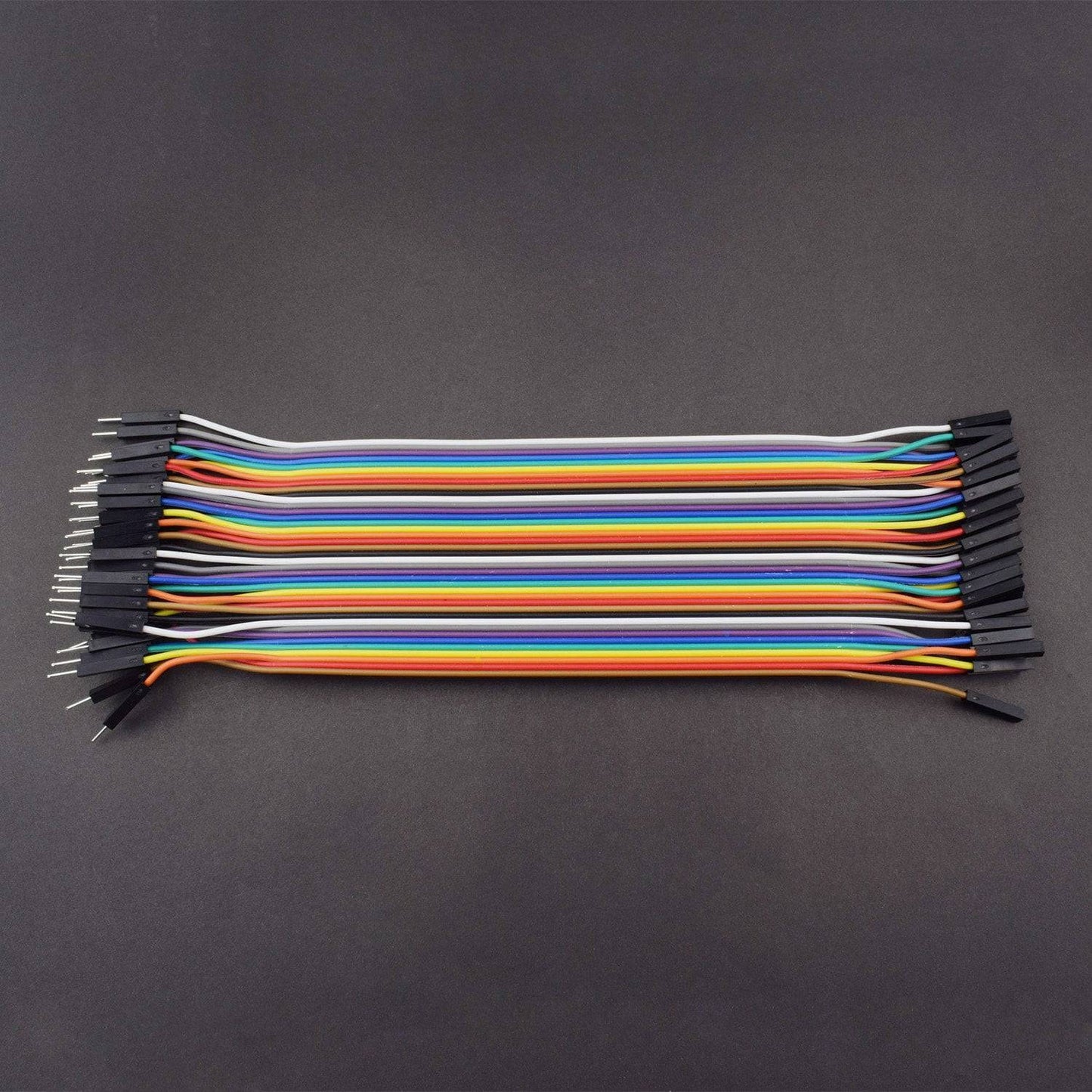
- Jumper wire(male to female) – 40 pieces
- 9v battery-1
- DC jack – 1
In this project you will see how to connect i2c LCD display to arduino and how to print on LCD display.
Each I2C bus consists of two signals: SCL and SDA. SCL is the clock signal, and SDA is the data signal. The clock signal is always generated by the current bus master; some slave devices may force the clock low at times to delay the master sending more data (or to require more time to prepare data before the master attempts to clock it out). This is called “clock stretching”
HARDWARE REQUIRED
- 16*2 i2c DISPLAY - 1
- Arduino uno with USB cable - 1
- Jumper wire(male to female) – 40 pieces
- 9v battery-1
- DC jack – 1
SOFTWARE REQUIRED
Arduino IDE 1.8.5 (programmable platform for Arduino)
Click To Download :https://www.arduino.cc/en/Main/Software

SPECIFICATIONS
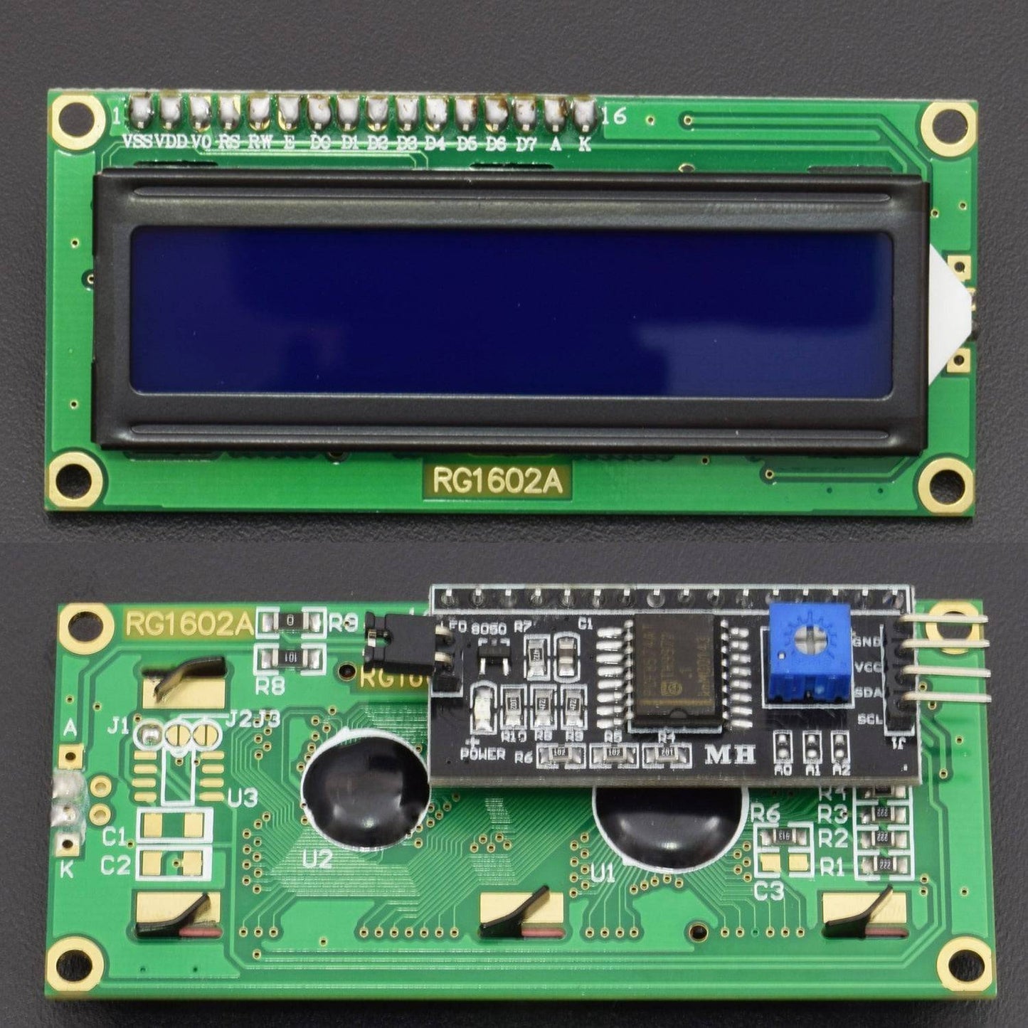
I2C LCD Serial Module
IC/I2C Interface Adapter Module is used for 16×2 LCD Display. It uses the PCF8574T IC chip which converts I2C serial data to parallel data for the LCD display. Also this interface module simplifies connecting an Arduino to a 16×2 Liquid Crystal display using only 4 wires.
- Supply Voltage: 5V
- Interface: I2C
- Compatible for 16×2 LCD
- Brightness and Contrast can be adjusted by the Potentiometer
16*2 LCD
- LCD Display Mode: STN, Positive, Transflective
- Display Color: Deep Blue/ Yellow Green
- Viewing Angle: 6H
- Driving Method : 1/16 duty, 1/5 bias
- Back Light : Yellow-Green LED backlight
- Outline Dimension: 803615.8 MAX
PIN DESCRIPTION
I2C LCD Serial Monitor

16*2 LCD
Symbol |
External Connection |
Function |
VSS |
Power Supply |
Signal GROUND for lcm |
VDD |
POWER SUPPLY for logic lcm |
|
V0 |
Contrast Adjust |
|
RS |
MPU |
Register Select Signal |
RW |
MPU |
Read/Write Select Signal |
E |
MPU |
Operation Enable Signal |
DB0~DB3 |
MPU |
Four Low order bidirectional three state bus lines. Used for data transfer between the MPU and LCM. These four are not used between 4 Bit operations. |
DB4~DB7 |
MPU |
Four high order bidirectional Three state bus lines used for data transfer between the MPU |
A |
LED BKL power Supply |
Power Supply for BKL |
K |

CIRCUIT CONNECTION
Attach the LCD display with I@C as given in diagram below:

I2C SHIELD |
Arduino uno |
Gnd |
Gnd |
Vcc |
5v |
SDA |
A4 |
SCL |
A5 |
CODE
Click to see the code or copy the link:
WORKING
Upload the code and must check your connection before uploading the code