


Generic
PRO Mini Atmega328 Development Board 5V/16MHz compatible with arduino IDE - AR032
PRO Mini Atmega328 Development Board 5V/16MHz compatible with arduino IDE - AR032
SKU:AR032
166 in stock
Couldn't load pickup availability
- For Bulk Order Click Here
- Need Customer Support?
- Free Delivery Above 999/-
Note: In case you receive a damaged or faulty product, please return it in the original box with all foam and packaging. Returns will not be accepted if further damage occurs due to improper packing.
If you order a product that is currently in Preorder, and the price of that item increases in the future, you will be required to pay the difference in price.
For refund/return/replacement, call us at +91 95995 94520 or email us at support@rees52.com
Delivery Time
Delivery Time
- Delivery time with the Express Shipping option is 2-3 working days, and with the Standard Shipping option is 5-6 working days. It varies based on location, reliant on courier services.
- Delivery time if the order item is on Preorder Status is 15-20 working days.
COD (Cash on Delivery)
COD (Cash on Delivery)
- For COD you have to pay extra charges of Rs 350/- before the shipment. (We will share the company QR Code, UPI ID or Account details for the same)
- Main Chip: Atmega328P-AU
- 14 digital input / output port: RX, TX, D2 ~~ D13
- 8 analog input ports: A0 ~ A7
- 1 pair TTL level serial transceiver port: RX / TX
- 6 PWM ports: D3, D5, D6, D9, D10, D11
- 16MHz clock frequency
- The bootloader is already installed in the board
Description:
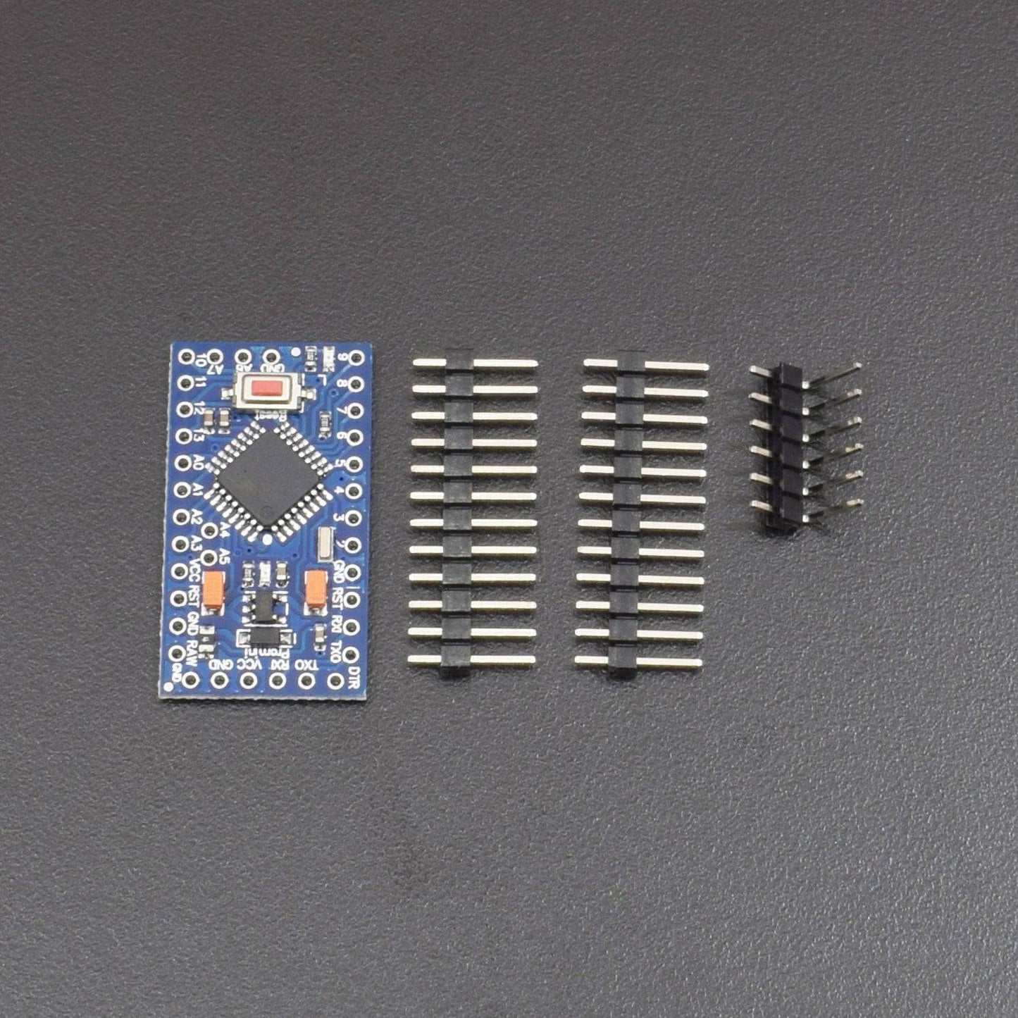
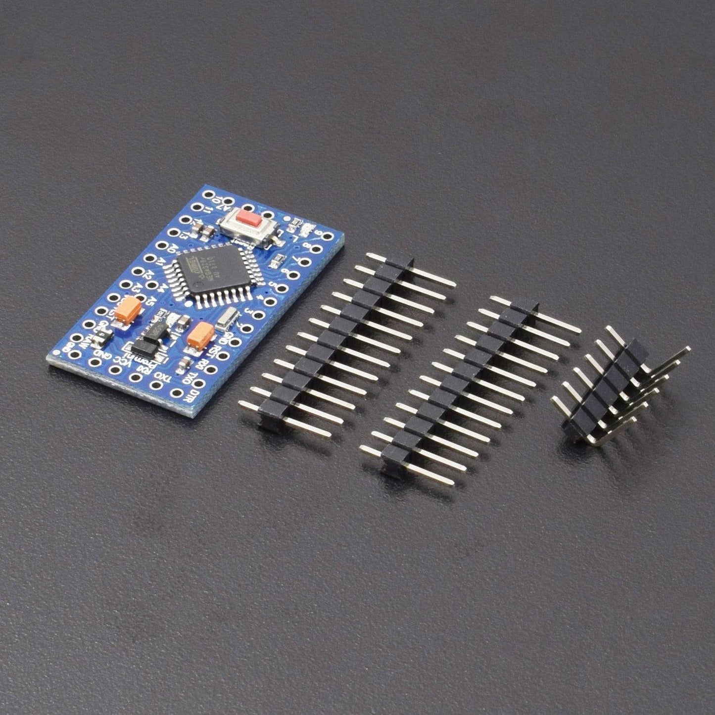
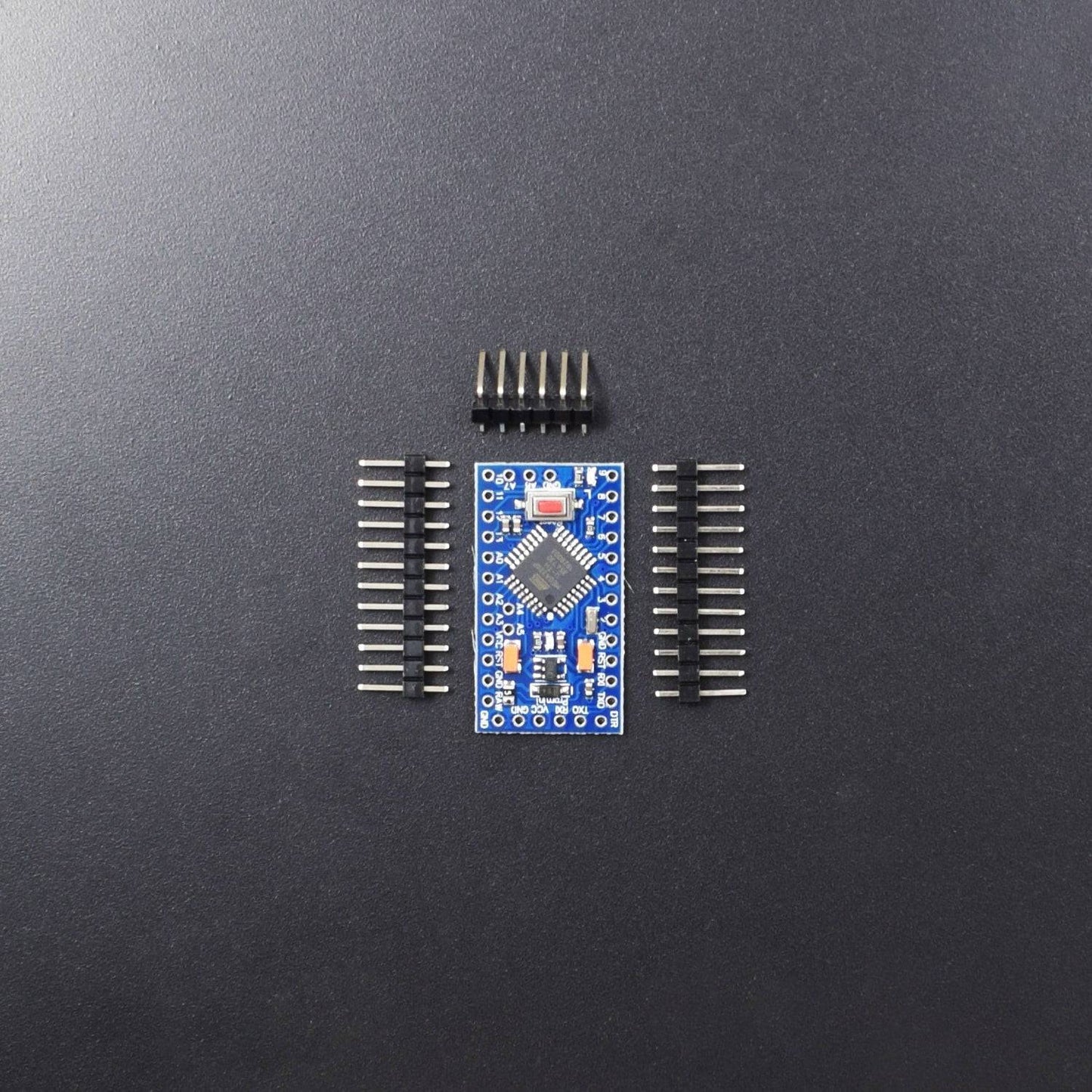
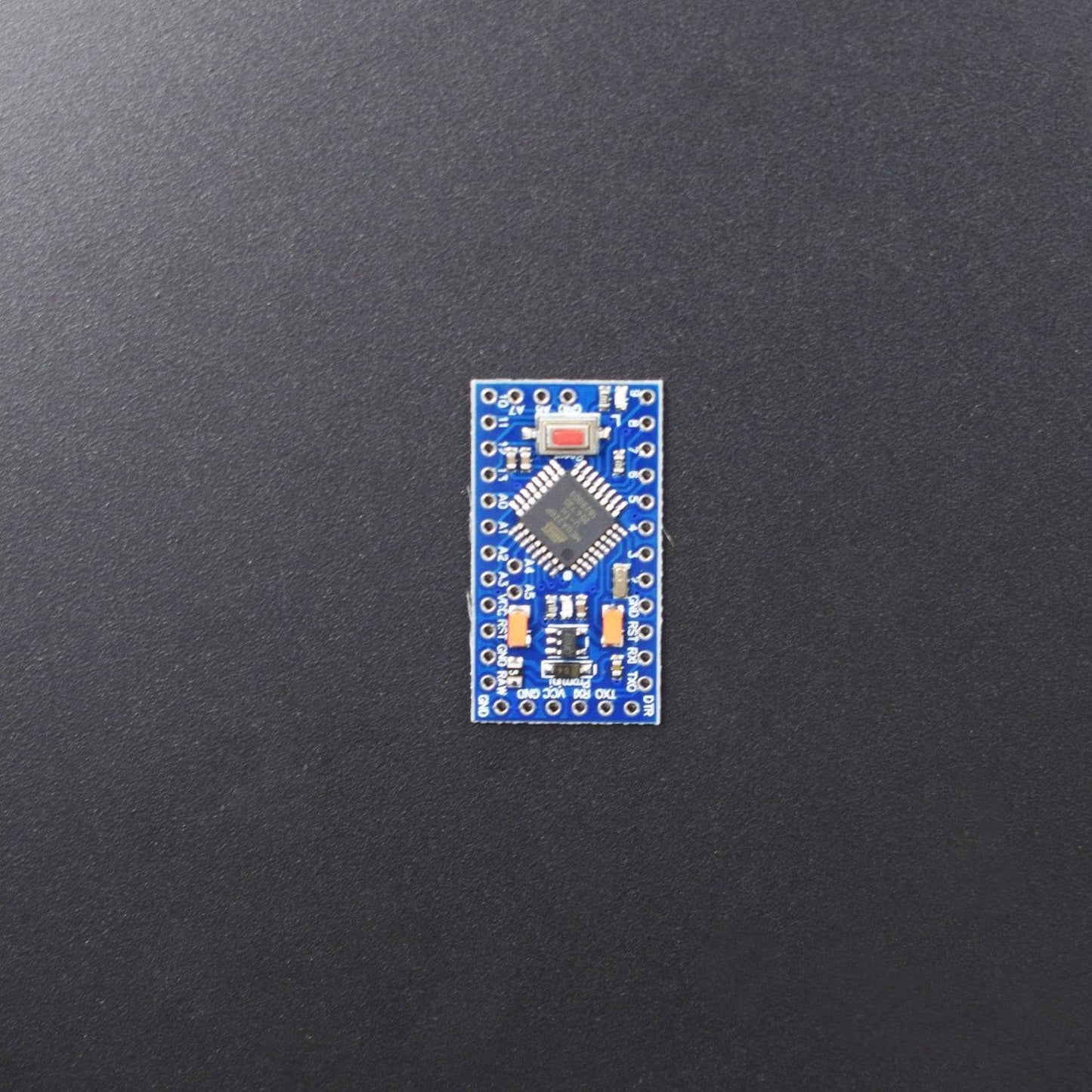
The ARDUIN0 Pro Mini is a microcontroller board based on the ATmega328. It has 14 digital input/output pins (of which 6 can be used as PWM outputs), 6 analog inputs, an onboard resonator, a reset button, and holes for mounting pin headers. A six-pin header can be connected to an FTDI cable or Sparkfun breakout board to provide USB power and communication to the board. The ARDUIN0 Pro Mini is intended for semi-permanent installation in objects or exhibitions. The board comes without pre-mounted headers, allowing the use of various types of connectors or direct soldering of wires. The pin layout is compatible with the ARDUIN0 Mini. There are two versions of the Pro Mini. One runs at 3.3V and 8 MHz, the other at 5V and 16 MHz.
Specification:
| Microcontroller | ATmega328 |
| Board Power Supply | 3.35 -12 V (3.3V model) or 5 - 12 V (5V model) |
| Circuit Operating Voltage | 3.3V or 5V (depending on model) |
| Digital I/O Pins | 14 |
| PWM Pins | 6 |
| UART | 1 |
| SPI | 1 |
| I2C | 1 |
| Analog Input Pins | 6 |
| External Interrupts | 2 |
| DC Current per I/O Pin | 40 mA |
| Flash Memory | 32KB of which 2 KB used by bootloader * |
| SRAM | 2 KB |
| EEPROM | 1 KB |
| Clock Speed | 8 MHz (3.3V versions) or 16 MHz (5V versions) |
Power:
The ARDUIN0 Pro Mini can be powered with an FTDI cable or breakout board connected to its six-pin header or with a regulated 3.3V or 5V supply (depending on the model) on the Vcc pin. There is a voltage regulator on board so it can accept voltage up to 12VDC. If you're supplying unregulated power to the board, be sure to connect to the "RAW" pin, not VCC.
The power pins are as follows:
RAW: For supplying a raw voltage to the board
VCC: The regulated 3.3 or 5 volt supply
GND: Ground pins
Memory:
The ATmega328 has 32 KB of flash memory for storing code (of which 0.5kB is used for the bootloader). It has 2 KB of SRAM and 1kBs of EEPROM (which can be read and written with the EEPROM library.
Input And Output:
Each of the 14 digital pins on the Pro Mini can be used as an input or output, using pinMode,digitalWrite, and digitalRead functions. They operate at 3.3 or 5 volts (depending on the model). Each pin can provide or receive a maximum of 40 mA and has an internal pull-up resistor (disconnected by default) of 20-50 kOhms.
In addition, some pins have specialized functions:
Serial: 0 (RX) and 1 (TX). Used to receive (RX) and transmit (TX) TTL serial data. These pins are connected to the TX-0 and RX-1 pins of the six-pin header.
External Interrupts 2 and 3. These pins can be configured to trigger an interrupt on a low value, a rising or falling edge, or a change in value. See the attachInterrupt function for details.
PWM: 3, 5, 6, 9, 10, and 11. Provide 8-bit PWM output with the analogWrite function.
SPI: 10 (SS), 11 (MOSI), 12 (MISO), 13 (SCK). These pins support SPI communication, which, although provided by the underlying hardware, is not currently included in the ARDUIN0 language.
LED: 13. There is a built-in LED connected to digital pin 13. When the pin is HIGH value, the LED is on, when the pin is LOW, it's off.
The Pro Mini has 8 analog inputs, each of which provides 10 bits of resolution (i.e. 1024 different values). Four of them are on the headers on the edge of the board; two (inputs 4 and 5) are on holes in the interior of the board. The analog inputs measure from ground to VCC.
Package Included:
1 x PRO Mini Atmega328 Development Board 5V/16MHz compatible with arduino IDE