

Hardware Required
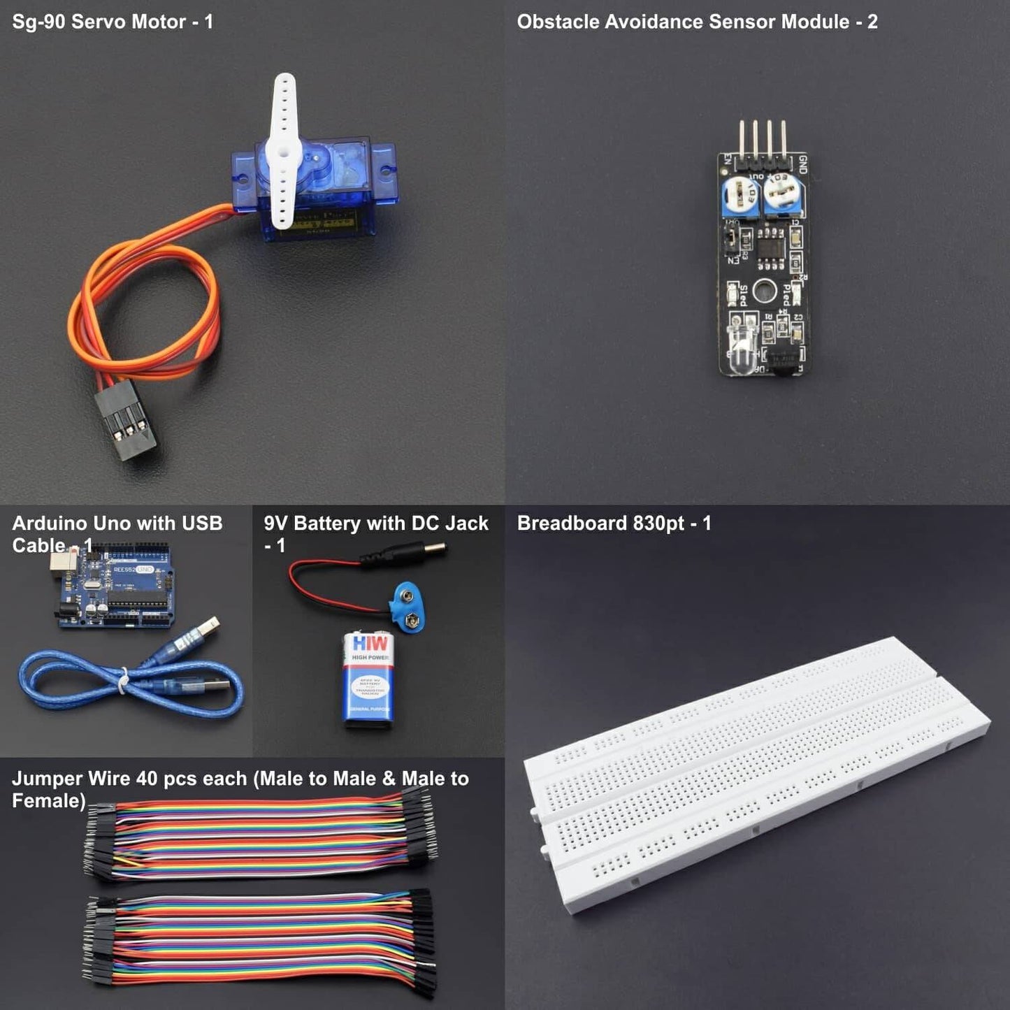
- Arduino Uno with USB Cable – 1
- SG-90 Servo Motor – 1
- Obstacle Avoidance Sensor Module – 2
- 9v Battery -1
- Battery with DC jack -1
- Breadboard 830 pt -1
- Jumper wire (Male to Male) - 40 pcs
- Jumper wire (Male to Female)- 40 pcs
Introduction
In this project, we have used this module for movement of certain parts or robotic components.
HARDWARE REQUIRED
- Arduino Uno with USB Cable – 1
- SG-90 Servo Motor – 1
- Obstacle Avoidance Sensor Module – 2
- 9v Battery -1
- Battery with DC jack -1
- Breadboard 830 pt -1
- Jumper wire (Male to Male) - 40 pcs
- Jumper wire (Male to Female)- 40 pcs
SOFTWARE REQUIRED
Arduino IDE 1.8.5 (programmable platform for Arduino)
Click To Download: https://www.arduino.cc/en/Main/Software
SPECIFICATIONS
Avoidance Sensor Module
The IR Obstacle Avoidance Sensor works by sending infrared light when the infrared light is reflected and received by the receiver your autonomous vehicle will stop. The sensor has a potentiometer which can be adjusted to change the detection distance.
- Length: 45mm
- Width: 15mm
- Height: 10mm
- Operating Voltage: 5v DC

SG-90 Servo Motor

Connector |
JR and FP connector |
Cable Length |
25 cm |
Operating System |
NO load ; : 0.12 sec / 60 degree (4.8V), 0.10 sec / 60 degree (6.0V) |
Stall Torque (4.8 V) |
1.6kg/cm |
Temperature |
-30~60'C |
Dead band width |
5 us |
Working Voltage |
3.5~6V |
Dimension |
1.26 in x 1.18 in x 0.47 in (3.2 cm x 3 cm x 1.2 cm) |
Weight |
4.73 oz (134 g) |
Motor Type |
3 pole |
CIRCUIT CONNECTION
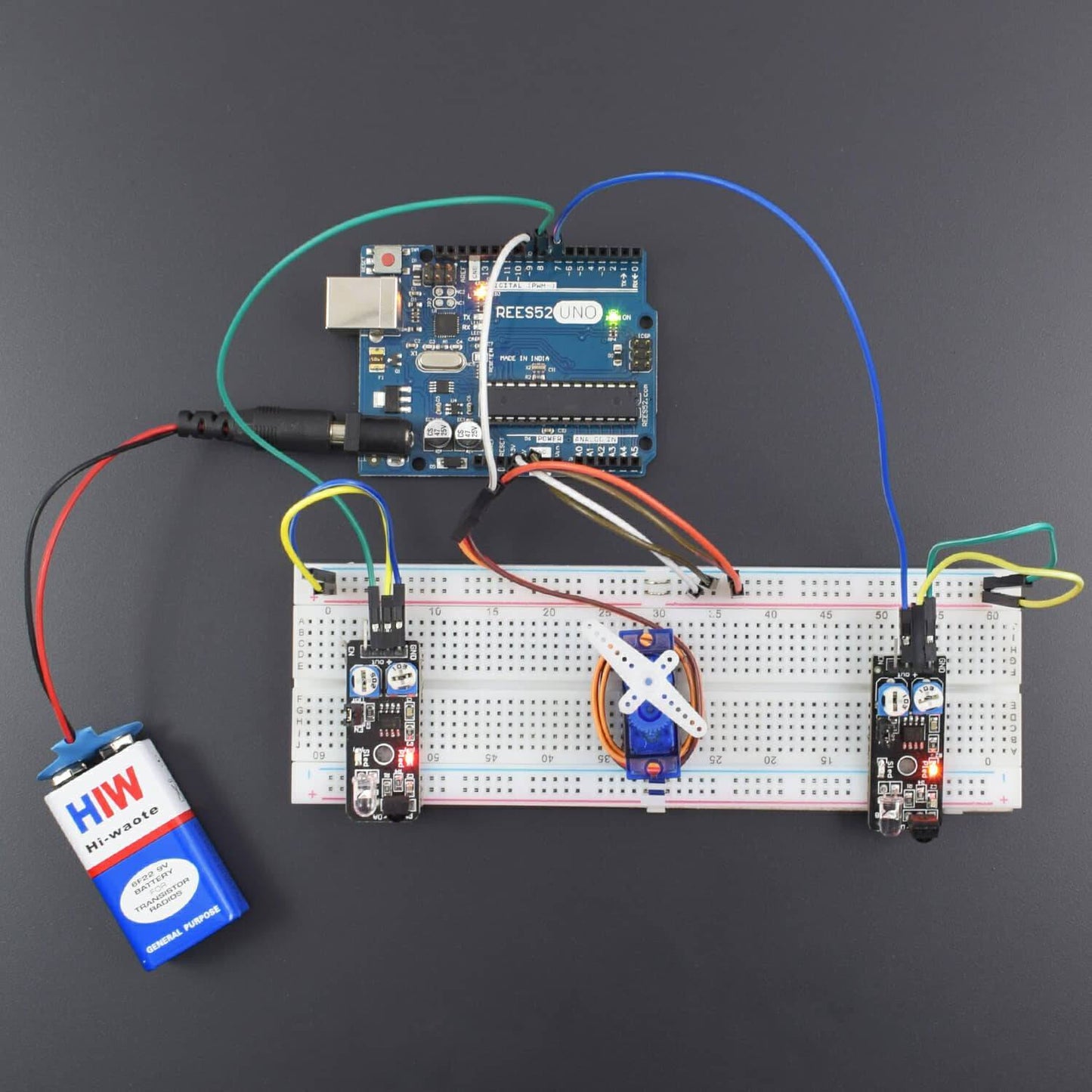
- Connect GND of Arduino Uno with Breadboard for further GND connections.
- Connect Pin 5V of Arduino Uno with Breadboard for further 5V power supply connections.
- Connect VCC of Servo motor with 5V rail of Breadboard.
- Connect GND of Servo Motor with GND rail of Breadboard.
- Connect Pin Signal of Servo Motor with Digital Pin 9 of Arduino.
- Connect VCC of both Obstacle avoidance Module with 5V rail of Breadboard.
- Connect GND of both Obstacle avoidance Module with GND rail of Breadboard.
- Connect Pin Signal of Obstacle avoidance Module 1 with Digital Pin 7 of Arduino Uno.
- Connect Pin Signal of Obstacle avoidance Module 2 with Digital Pin 8 of Arduino Uno.

NOTE: Please adjust the sensitivity by the potentiometer over the module so that it can show a better result.
CODE
Click to download the code: https://drive.google.com/open?id=1Gv4l6H76nWt07tUEJO_E0J181nh1r2rO
WORKING
Welcome to the Arduino Based project which consists of Servo Motor and Obstacle Avoidance Module. The basic working principle of Obstacle avoidance module is being described here. This Infrared Obstacle Avoidance Sensor returns a signal when it detects an object in range. The range of the sensor is around 2-40 cm is distance. It operates at 3.5 to 5V around 20 milliamps. Infrared obstacle avoidance sensor is designed to detect obstacles or the difference in reflective services. One application is to help a wheeled robot avoid obstacles with a sensor to react to adjustable distance settings. This device has an infrared transmitter and receiver that forms the sensor pair. The transmitter LED emits a certain frequency of infrared, which the receiver LED will detect. The receiving LED will detect some of the signal back and will trigger the digital on/off “signal” pin when a specific threshold “distance” has been detected. This way we can also control the movement of various robotic parts attached with the circuit.
Most boards will have 2 potentiometers, one of which is to adjust how sensitive the sensor is. You can use it to adjust the distance from the object at which the sensor detects it. Typically, the other potentiometer, which changes the transmitter IR frequency is not adjusted.


