


vendor-unknown
Making a RF Wireless Communicator using Arduino uno and Arduino pro mini - KT864
Making a RF Wireless Communicator using Arduino uno and Arduino pro mini - KT864
SKU:KT864
99 in stock
Couldn't load pickup availability
- For Bulk Order Click Here
- Need Customer Support?
- Free Delivery Above 999/-
Note: In case you receive a damaged or faulty product, please return it in the original box with all foam and packaging. Returns will not be accepted if further damage occurs due to improper packing.
If you order a product that is currently in Preorder, and the price of that item increases in the future, you will be required to pay the difference in price.
For refund/return/replacement, call us at +91 95995 94520 or email us at support@rees52.com
Delivery Time
Delivery Time
- Delivery time with the Express Shipping option is 2-3 working days, and with the Standard Shipping option is 5-6 working days. It varies based on location, reliant on courier services.
- Delivery time if the order item is on Preorder Status is 15-20 working days.
COD (Cash on Delivery)
COD (Cash on Delivery)
- For COD you have to pay extra charges of Rs 350/- before the shipment. (We will share the company QR Code, UPI ID or Account details for the same)


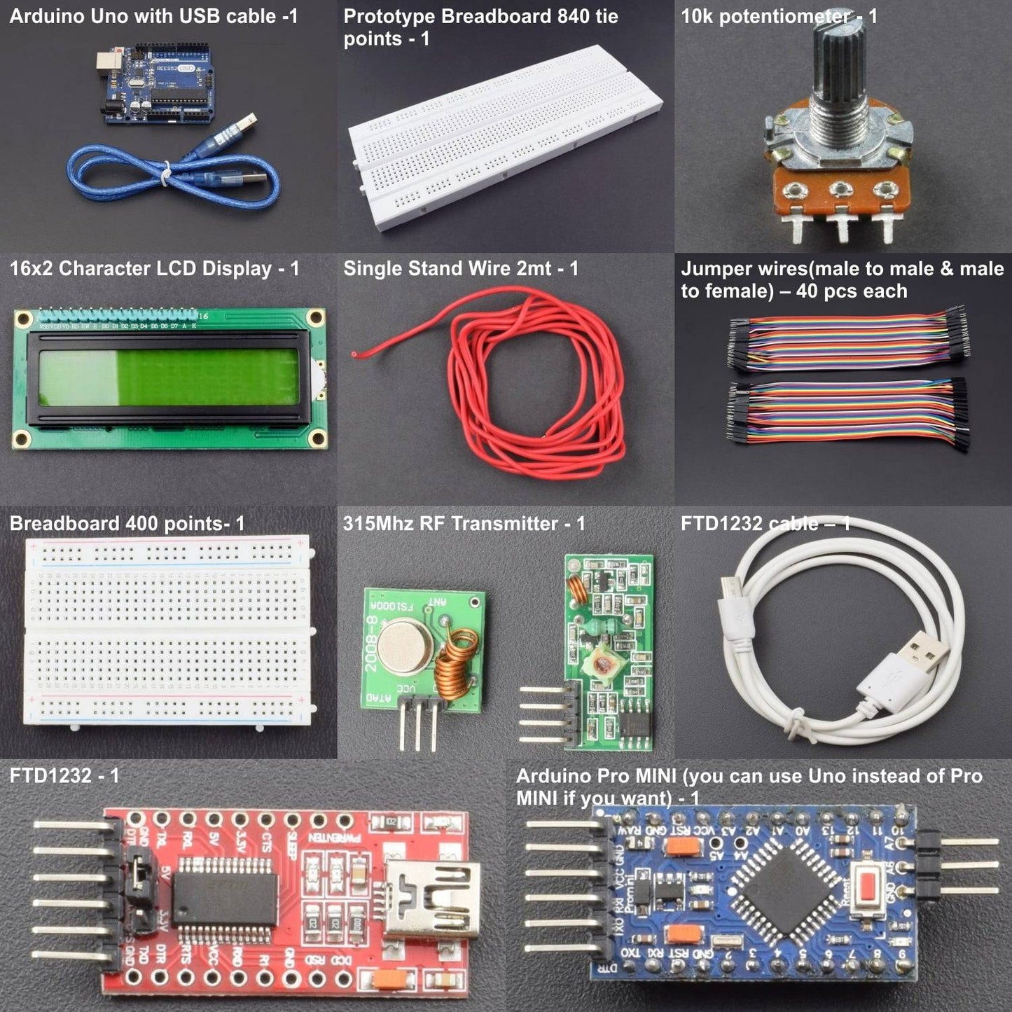
- Arduino Uno with USB cable -1
- Arduino Pro MINI (you can use Uno instead of Pro MINI if you want)
- 16x2 LCD Display-1
- 315Mhz RF Transmitter + Receiver Module Link - 1
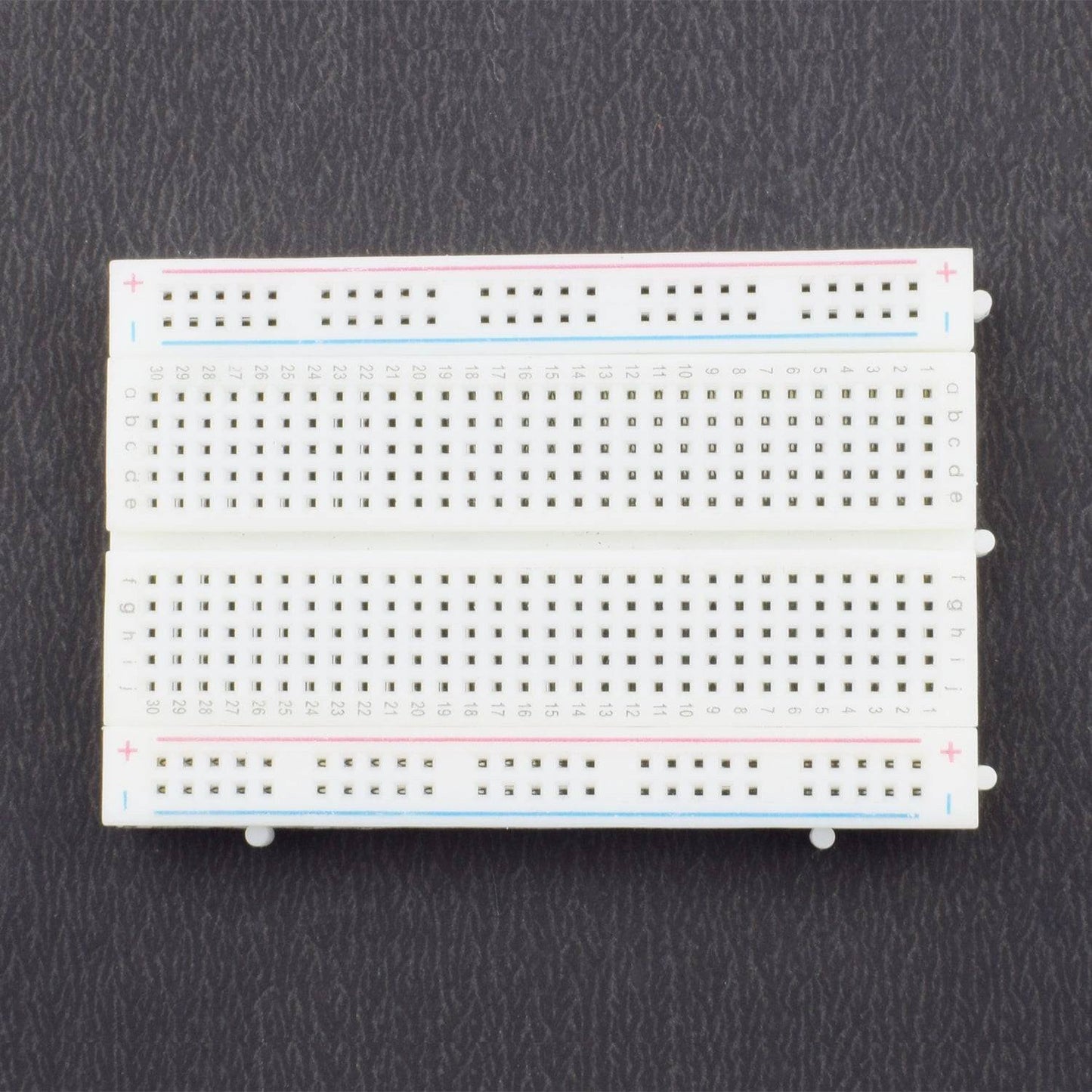
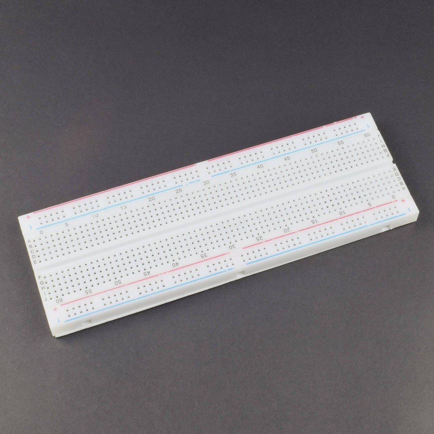
- Breadboard 840 points- 1
- Male-to-male Jumper wires – 40 pieces
- male-to-female Jumper wire – 40 pieces
- 10k pot-1
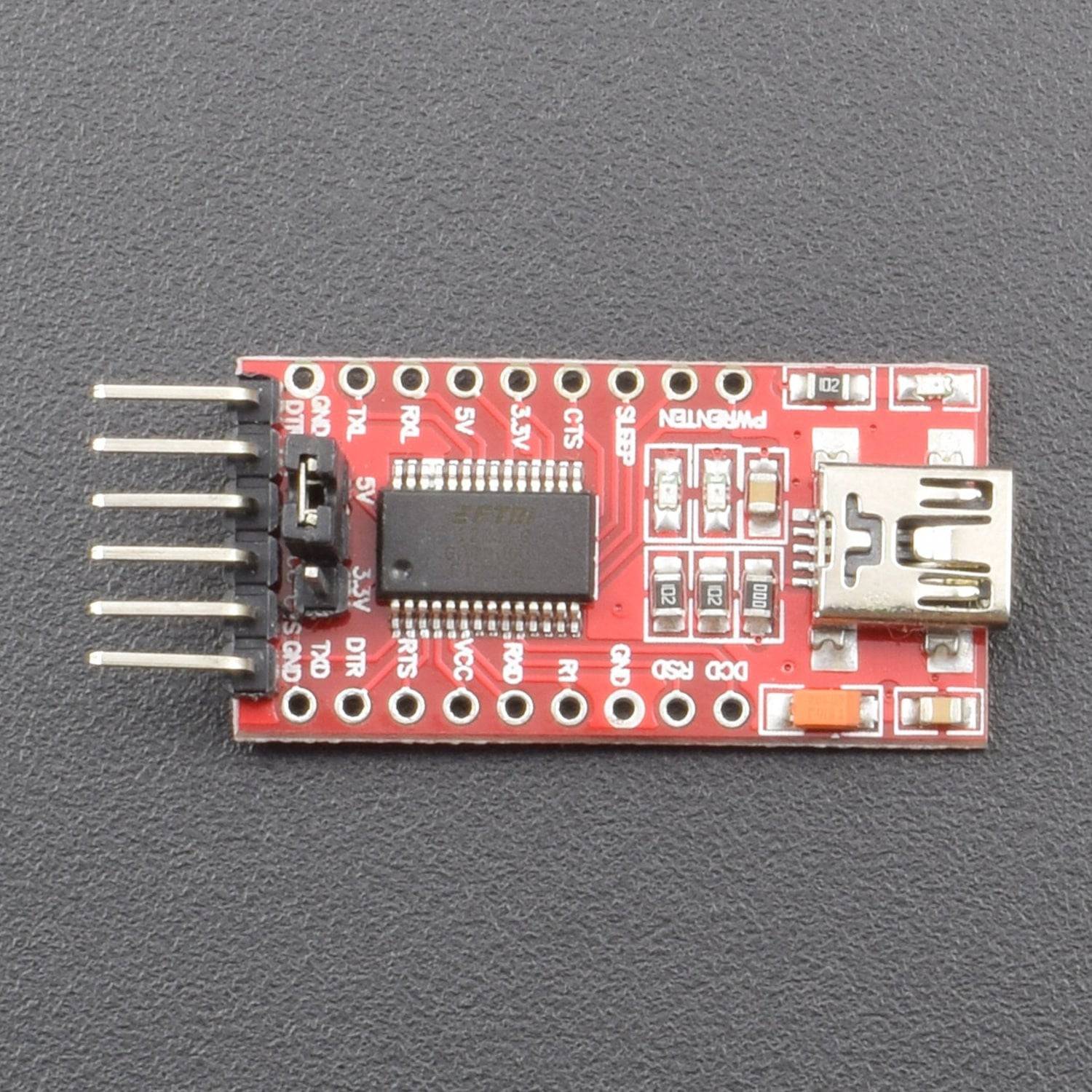
- FTD1232 with cable – 1
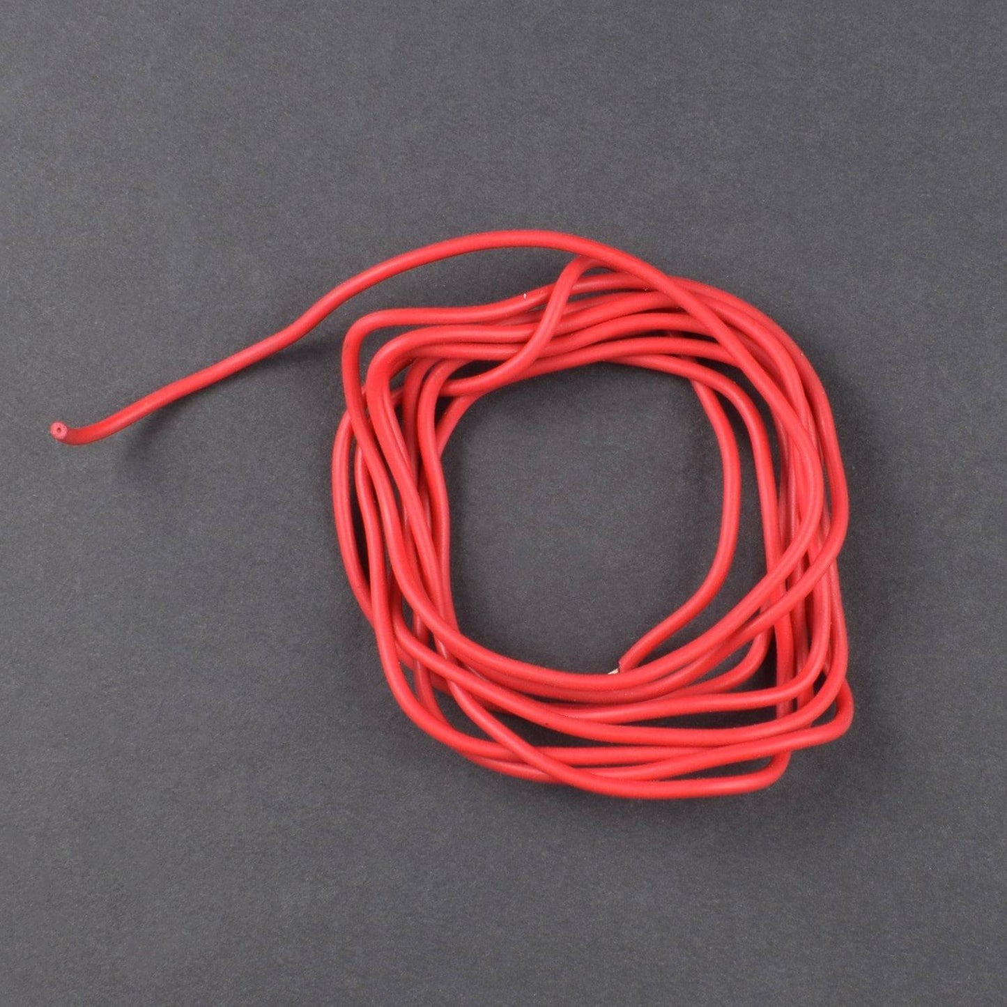
- Single stand wire 2MT - 1
- Breadboard 400 points- 1
HARDWARE REQUIRED
- Arduino Uno with USB cable -1
- Arduino Pro MINI (you can use Uno instead of Pro MINI if you want)
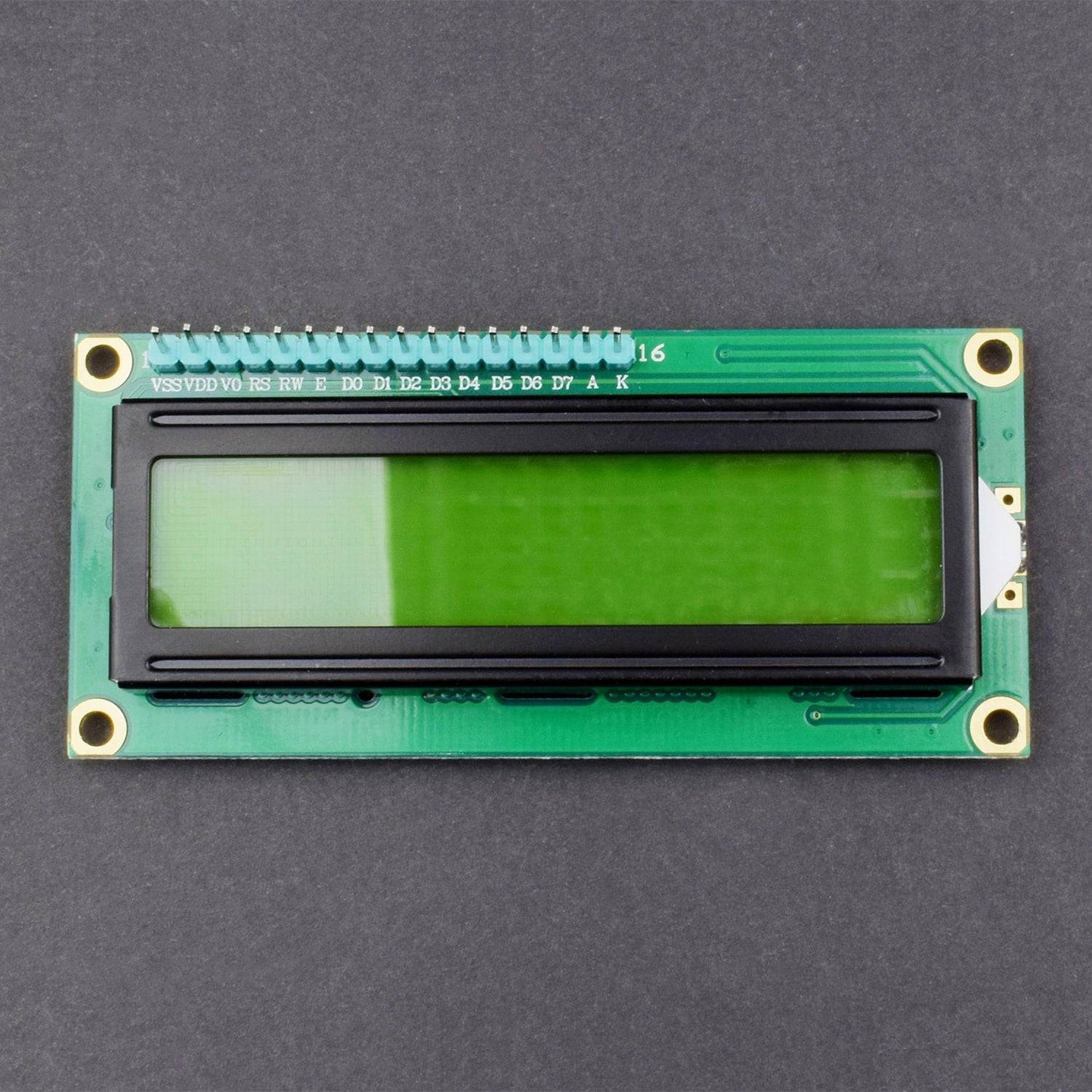
- WH1602 or HD44780 16x2 Character LCD Display-1
- 433Mhz or 315Mhz RF Transmitter + Receiver Module Link - 1
- Prototype Breadboard 840 tie points- 1
- Male-to-male Jumper wires – 40 pieces
- male-to-female Jumper wire – 40 pieces
- 10k potentiometer-1
- FTD1232 with FTD1232 cable – 1
- Single stand wire 2MT - 1
- Breadboard 400 points- 1
SPECIFICATIONS
LCD
- LCD Display Mode: STN, Positive, Transflective
- Display Color: Deep Blue/ Yellow Green
- Viewing Angle: 6H
- Driving Method : 1/16 duty, 1/5 bias
- Back Light : Yellow-Green LED backlight
- Outline Dimension: 803615.8 MAX
CAUTIONS
- The LCD panel is made by glass. Any mechanical shock (eg. dropping from high place) will damage the LCD module.
- Do not add excessive force on the surface of the display, which may cause the Display color change abnormally.
- The polarizer on the LCD is easily get scratched. If possible, do not remove the LCD protective film until the last step of installation.
- Never attempt to disassemble or rework the LCD module.
- Only Clean the LCD with Isopropyl Alcohol or Ethyl Alcohol. Other solvents (eg.water) may damage the LCD.
- When mounting the LCD module, make sure that it is free form twisting, warping and distortion.
- Ensure to provide enough space(with cushion) between case and LCD panel to prevent external force adding on it, or it may cause damage to the LCD or degrade the display result.
- Only hold the lCD module by its side. Never hold LCD module by add force on the heat seal ot TAB.
- Never add force to component of the LCD module. It may cause invisible damage or degrade of the reliability.
- LCD module could be easily damaged by static electricity. Be careful to maintain an optimum anti-static work environment to protect the LCD module.
- When peeling off the protective film from LCD, static charge may cause abnormal display pattern. It is normal and will resume to nomal in a short while.
- Take care and prevent get hurt by the LCD panel sharp edge.
- Never operate the LCD module exceed the absolute maximum ratings.
- Keep the signal line as short as possible to prevent noisy signal applying to LCD module.
- Never apply signal to the LCD module without power supply.
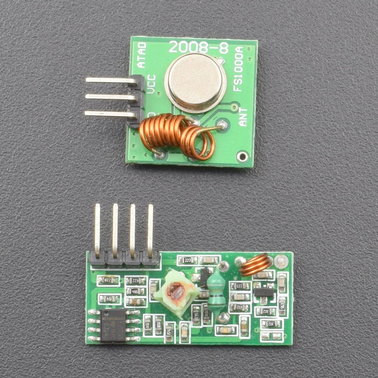
- Receiver module parameter
- Product Model MX-05V
- Operating voltage: DC5V
- Quiescent current: 4mA
- Receiving frequency: 433MHZ
- Receiver sensitivity:-105DB
- Size: 30 * 14 * 7mm
- An extra antenna is needed, please use spiral 50Ω a quarter wavelength antenna
- Transmitter module parameter
- Product Model: MX-FS-03V
- Launch distance :20-200 meters (different voltage, different results)
- Operating voltage :3.5-12V
- Dimensions: 19 * 19mm
- Operating mode: AM
- Transfer rate: 4KB/s
- Transmitting power: 10mW
- Transmitting frequency: 433M
- Pinout from left to right: (DATA; VCC; GND)
SOFTWARE REQUIRED
Arduino IDE ((Programmable platform for Arduino boards)
You can download it from this link: https://www.arduino.cc/en/Main/Software

PIN DESCRIPTION
10K POTENTIOMETER

16*2 LCD DISPLAY


433 MHZ OR 315 MHZ RF TRANSMITTER + RECEIVER MODULE LINK

FTD1232 WITH FTD1232 CABLE

ARDUINO PRO MINI


STEP-1
How to upload sketches on Arduino Pro MINI.
- Remove Atmega328 from Arduino UNO
- Using male-to-female cables connect Pro MINI to UNO
RX-RX;
TX-TX;
RST-RST;
GND-GND;
VCC-+5V
- Change in Tools – Board - Arduino Pro or Pro MINI
- Upload sketch
STEP-1 RECEIVER CODE
Before uploading the given code , Download this Library
http://www.resistorpark.com/arduino-virtualwire-library-download/
#include
#include
LiquidCrystal lcd(7, 6, 5, 4, 3, 2);
char cad[100];
int pos = 0;
void setup()
{
lcd.begin(16, 2);
lcd.setCursor(1, 0);
vw_setup(2000);
vw_rx_start();
}
void loop()
{
byte buf[VW_MAX_MESSAGE_LEN];
byte buflen = VW_MAX_MESSAGE_LEN;
int i;
if ( vw_get_message(buf, &buflen) )
{
if (pos < 2)
lcd.setCursor(0, pos);
else
{
pos = 0;
lcd.clear();
}
for (i = 1; i < buflen; i++)
{
lcd.print((char)buf[i]);
pos++;
}}}
STEP-3 TRANSMITTER CODE
#include
char cad[100];
int i=0;
void setup()
{
Serial.begin(9600);
vw_setup(2000);
Serial.print("End with "." each data");
}
void loop()
{
if( Serial.available() > 0)
{
cad[i] = Serial.read();
i++;
}
if( cad[i-1] == '.')
{
cad[i] = '';
i=0;
vw_send((byte *)cad, strlen(cad));
delay(400);
}
}
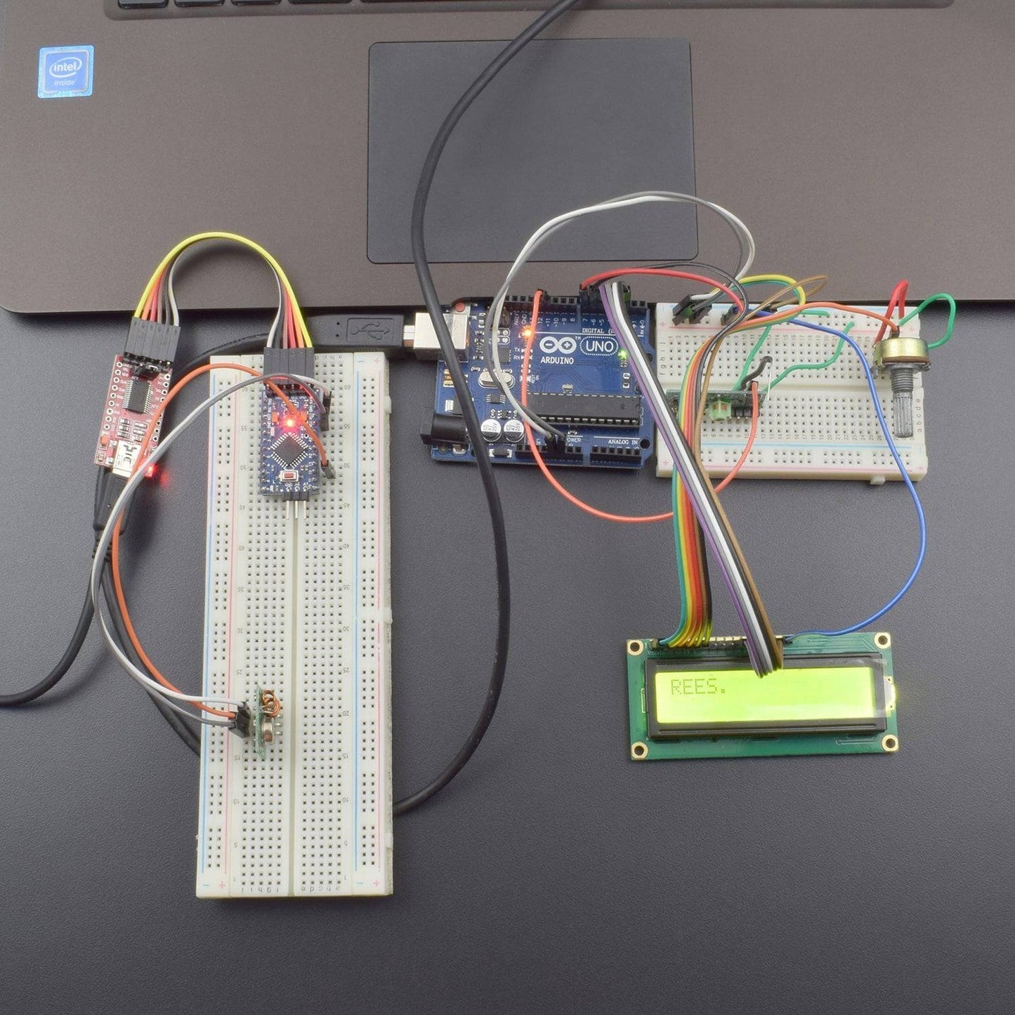
CIRCUIT DIAGRAM - RECEIVER

CIRCUIT DIAGRAM - TRANSMITTER

Connect the modules according to the given diagram
OUTPUT
Open serial monitor and type message and the text with Eg hello. Press enter message will show on your lcd 16*2.Print any message to the Serial Monitor window. End with point ".'
Press Enter
