


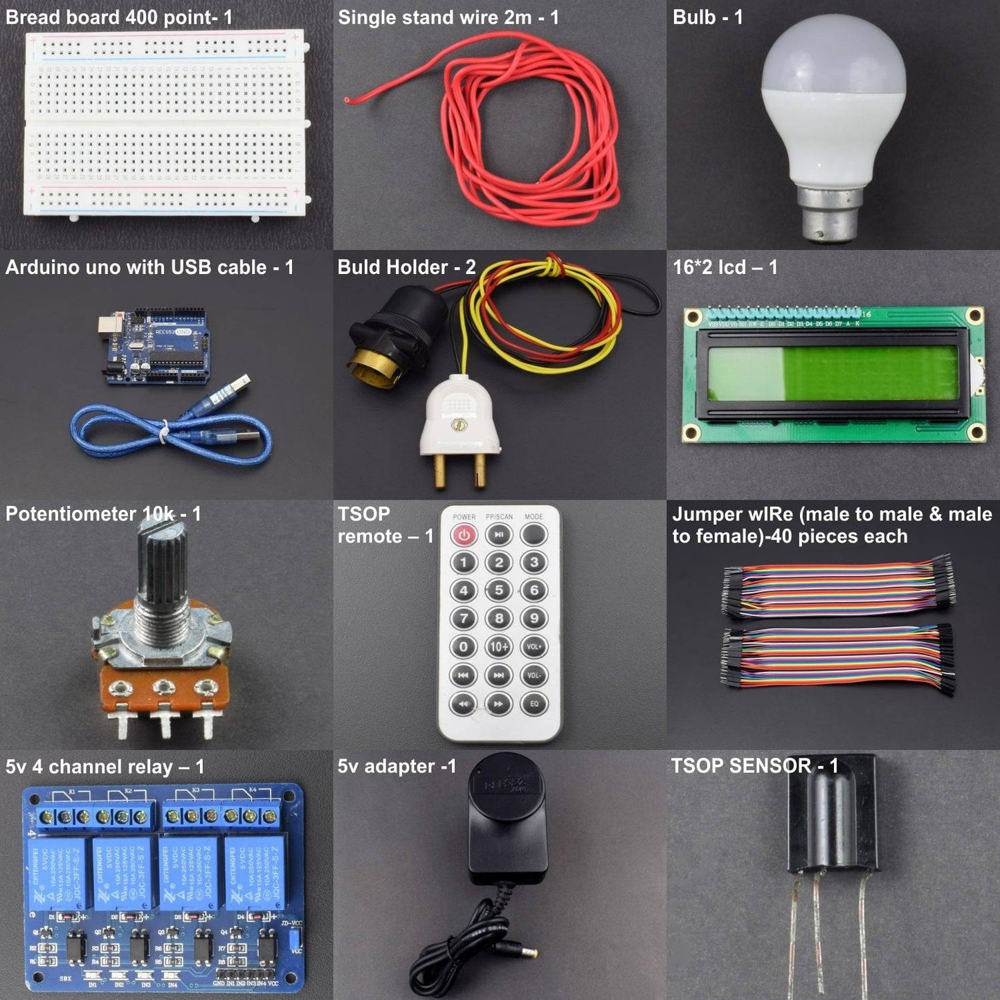
KIT INCLUDES:
- Voltage regulator IC 7805 - 1
- LM35 Temperature sensor - 1
- LM358 IC - 1
- Resistor 10K - 2
- 10K Pot - 1
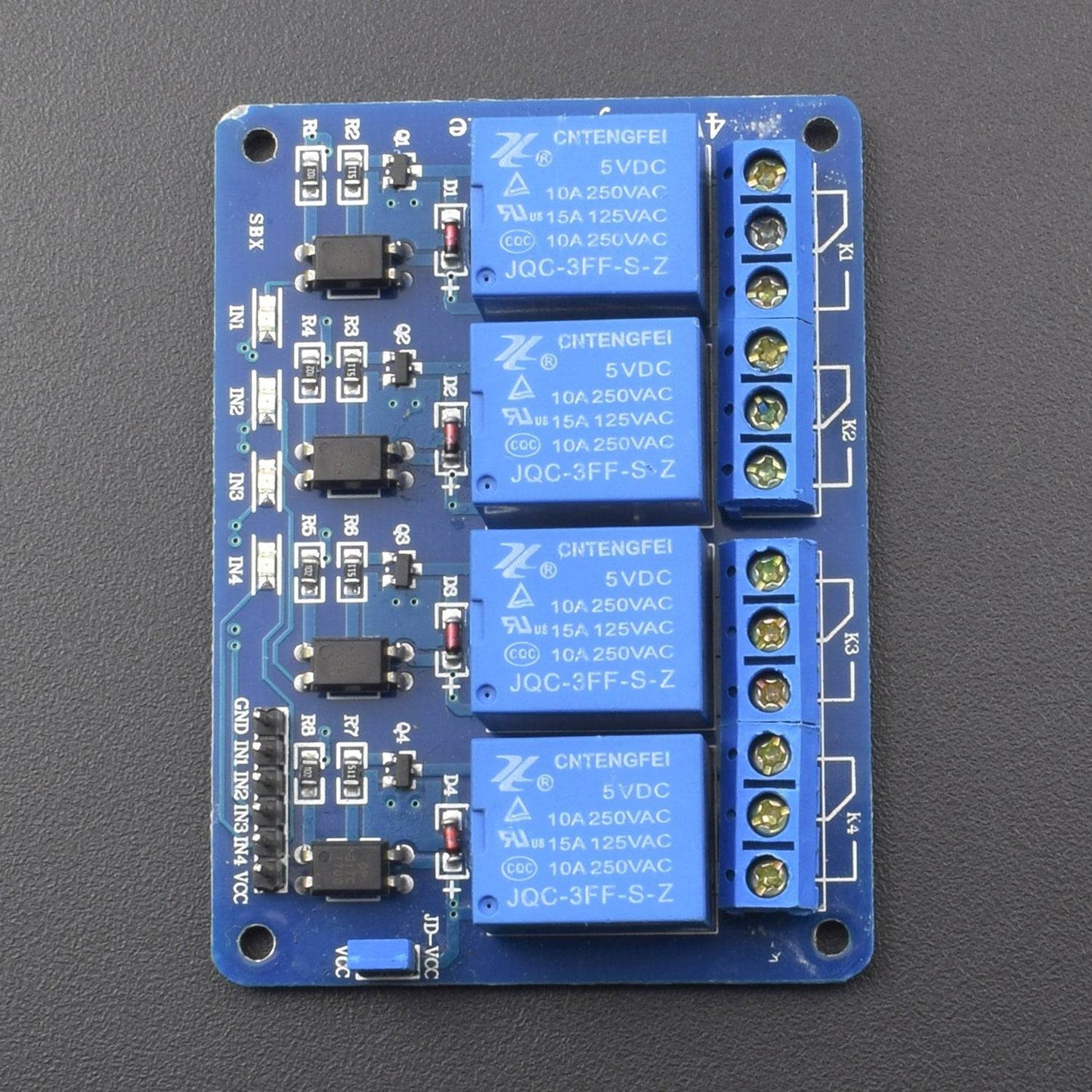
- Relay module 4 channel 5V - 1
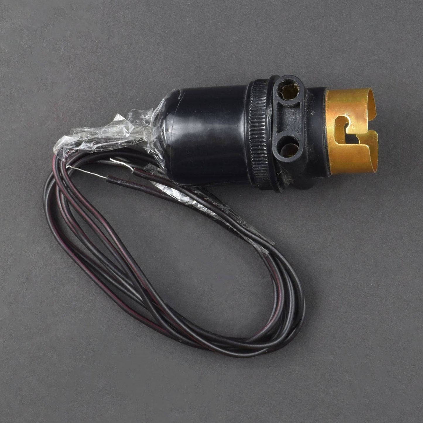
- bulb and bulb holder – 1(Not included in kit)
- Battery 9V with snapper - 1
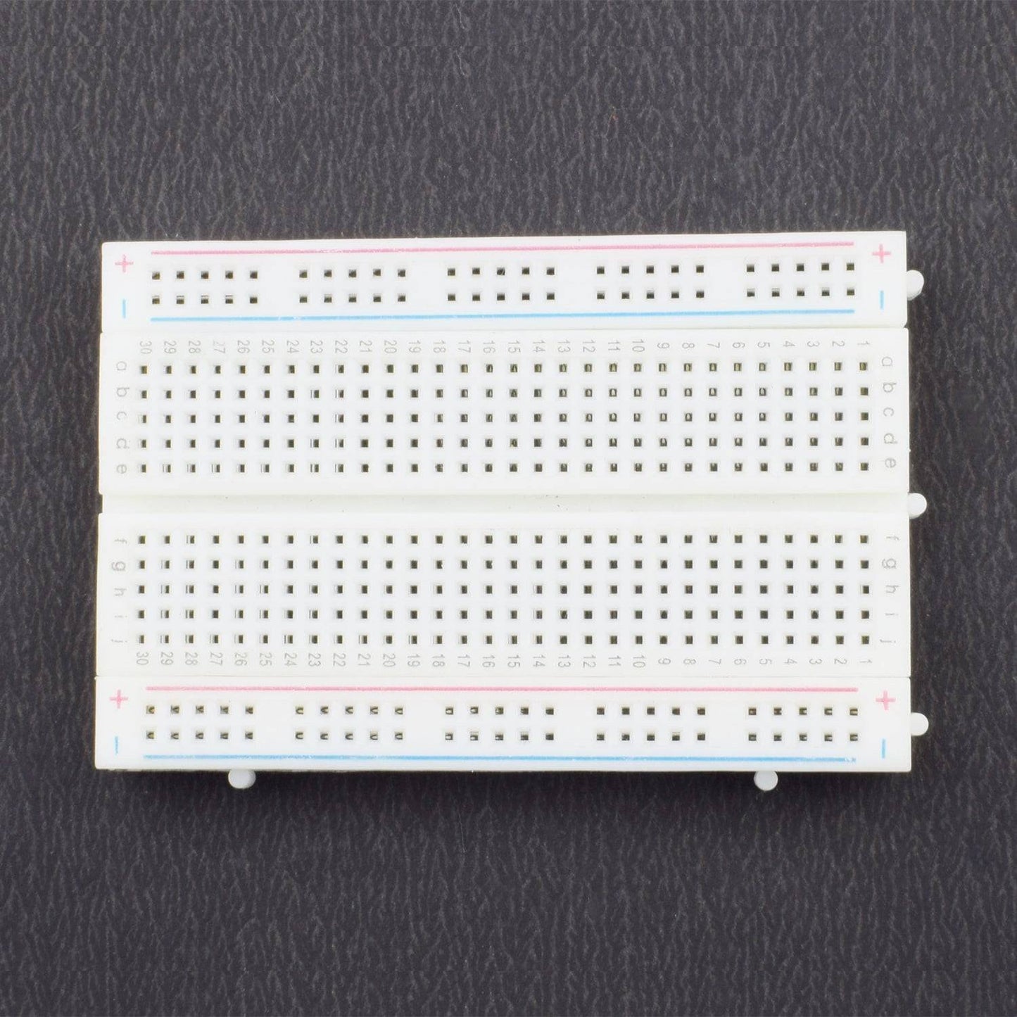
- Breadboard 840 points - 1
- Jumper wire(male to female) – 40 pieces
- Single stand wire 2m – 1
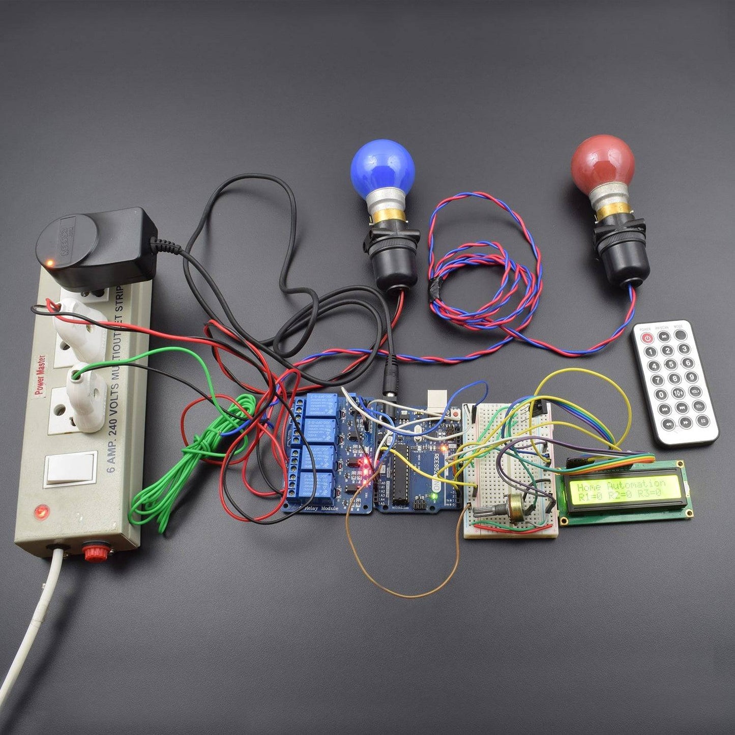
An Arduino home automation project can be made using different wireless technology like Bluetooth, WiFi, Android Mobile or using IR remote control. We use the relay in arduino home automation project to control the home appliances. We use IR remote control to control the home appliances remotely.
HARDWARE REQUIRED
- Voltage regulator IC 7805 - 1
- LM35 Temperature sensor - 1
- LM358 IC - 1
- Resistor 10K - 2
- 10K Pot - 1
- Relay module 1 channel 5V - 1
- bulb and bulb holder – 1(Not included in kit)
- Battery 9V with snapper - 1
- Breadboard 840 points - 1
- Jumper wire(male to female) – 40 pieces
- Single stand wire 2m – 1
SPECIFICATIONS
- LCD
- LCD Display Mode: STN, Positive, Transflective
- Display Color: Deep Blue/ Yellow Green
- Viewing Angle: 6H
- Driving Method : 1/16 duty, 1/5 bias
- Back Light : Yellow-Green LED backlight
- Outline Dimension: 803615.8 MAX
CAUTIONS
• The LCD panel is made by glass. Any mechanical shock (eg. dropping from high place) will damage the LCD module.
• Do not add excessive force on the surface of the display, which may cause the Display color change abnormally.
• The polariser on the LCD is easily get scratched. If possible, do not remove the LCD protective film until the last step of installation.
• Never attempt to disassemble or rework the LCD module.
• Only Clean the LCD with Isopropyl Alcohol or Ethyl Alcohol. Other solvents (eg.water) may damage the LCD.
• When mounting the LCD module, make sure that it is free form twisting, warping and distortion.
• Ensure to provide enough space(with cushion) between case and LCD panel to prevent external force adding on it, or it may cause damage to the LCD or degrade the display result.
• Only hold the lCD module by its side. Never hold LCD module by add force on the heat seal ot TAB.
• Never add force to component of the LCD module. It may cause invisible damage or degrade of the reliability.
• LCD module could be easily damaged by static electricity. Be careful to maintain an optimum anti-static work environment to protect the LCD module.
• When peeling off the protective film from LCD, static charge may cause abnormal display pattern. It is normal and will resume to nomal in a short while.
• Take care and prevent get hurt by the LCD panel sharp edge.
• Never operate the LCD module exceed the absolute maximum ratings.
• Keep the signal line as short as possible to prevent noisy signal applying to LCD module.
• Never apply signal to the LCD module without power supply.
• IC chip(eg. TAB or COG) is sensitive to the light. Strong lighting environment could possibly cause malfunction. Light sealing structure casing is recommend.
• LCD module reliability may be reduced by temperature shock.
2. 5V 4-channel relay module
- Drive current: 20mA
- Control signal: 5V/12V/24V TTL level
- Maximum switching voltage: 250VAC 30VDC
- Standard interface that can be controlled directly by microcontroller (Arduino, 8051, AVR, PIC, DSP, ARM, ARM, MSP430, TTL logic)
- Active Low
- Number of Relays: 4
- Control signal: TTL level
- Rated load: 7A/240VAC 10A/125VAC 10A/28VDC
- Contact action time: 10ms/5ms
SOFTWARE REQUIRED
Arduino IDE ( programmable software for Arduino boards )
You can download the software from this link : https://www.arduino.cc/en/Main/Software

PIN DESCRIPTION
- 10 k Potentiometer

- 16*2 LCD shield

- 5V 1-Channel Relay module


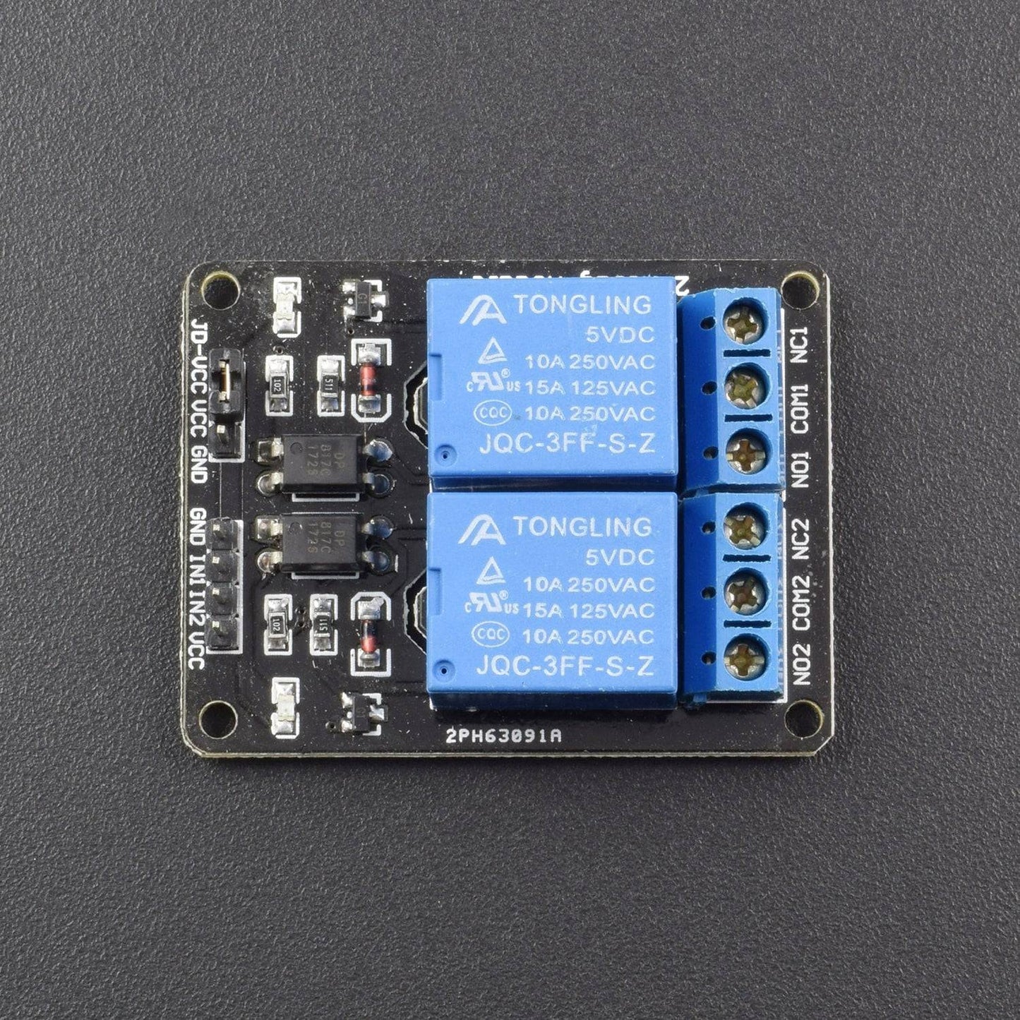
when the signal port is at low level, the signal light will light up and the opt coupler 817c (it transforms electrical signals by light and can isolate input and output electrical signals) will conduct, and then the transistor will conduct, the relay coil will be electrified, and the normally open contact of the relay will be closed. When the signal port is at high level, the normally closed contact of the relay will be closed. So you can connect and disconnect the load by controlling the level of the control signal port.
Input:
VCC: Positive supply voltage
GND: Ground
IN1--IN4: Relay control port
Output:
Connect a load, DC 30V/10A,AC 250V/10A
- TSOP Sensor

- Supply Voltage: –0.3...6.0 V.
- Supply Current: 5 mA.
- Output Voltage: –0.3...6.0 V.
- Output Current: 5 mA.
- Junction Temperature: 100 °C
- Storage Temperature Range: –25...+85 °C
- Operating Temperature Range: –25...+85°C
Available TSOP with Different Carrier Frequencies
CIRCUIT DESCRIPTION

-
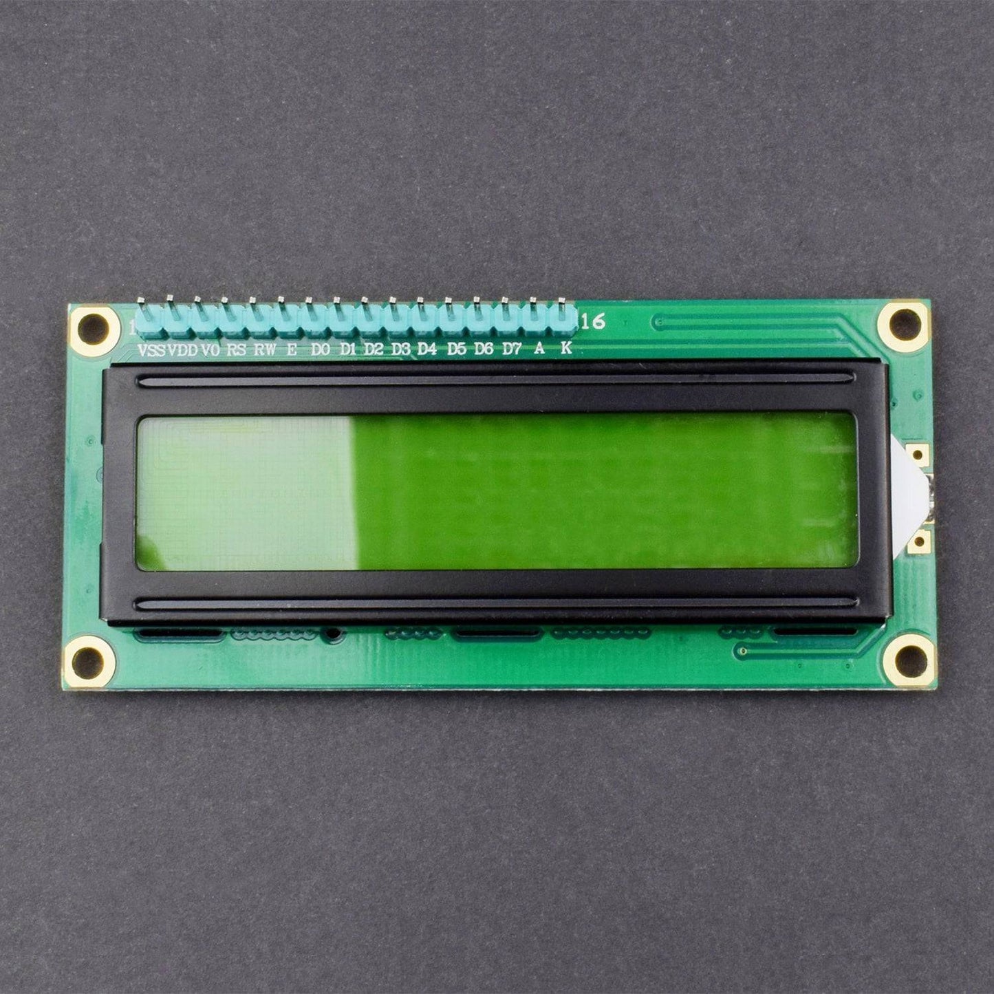
LCD Connections with Arduino
- RS – Digital Pin 3
- RW – GND
- E – Digital Pin 2
- D4 – Digital Pin 4
- D5 – Digital Pin 5
- D6 – Digital Pin 6
- D7 – Digital Pin 7
Arduino Connection with Relay
- A0 – Relay1(FAN)
- A1 – Relay2(BULB)
- A2 – Relay3(AC)
- TSOP Connection with Arduino
- Out – Digital Pin 9(PWM)
The IR receiver is connected to digital pin 9. This pin should be a PWM pin. The relay is connected to analog pin A0, A1, and A2. We have used the MCT2E opt coupler to isolate the signal from the Arduino and load connected to the relay. This opt coupler also provides the isolation from the noise and short circuit at relay side.
At the output side of the MCT2E, a BC548 NPN transistor is connected to trigger the relay. Here transistor simply acting as a switch for the relay.
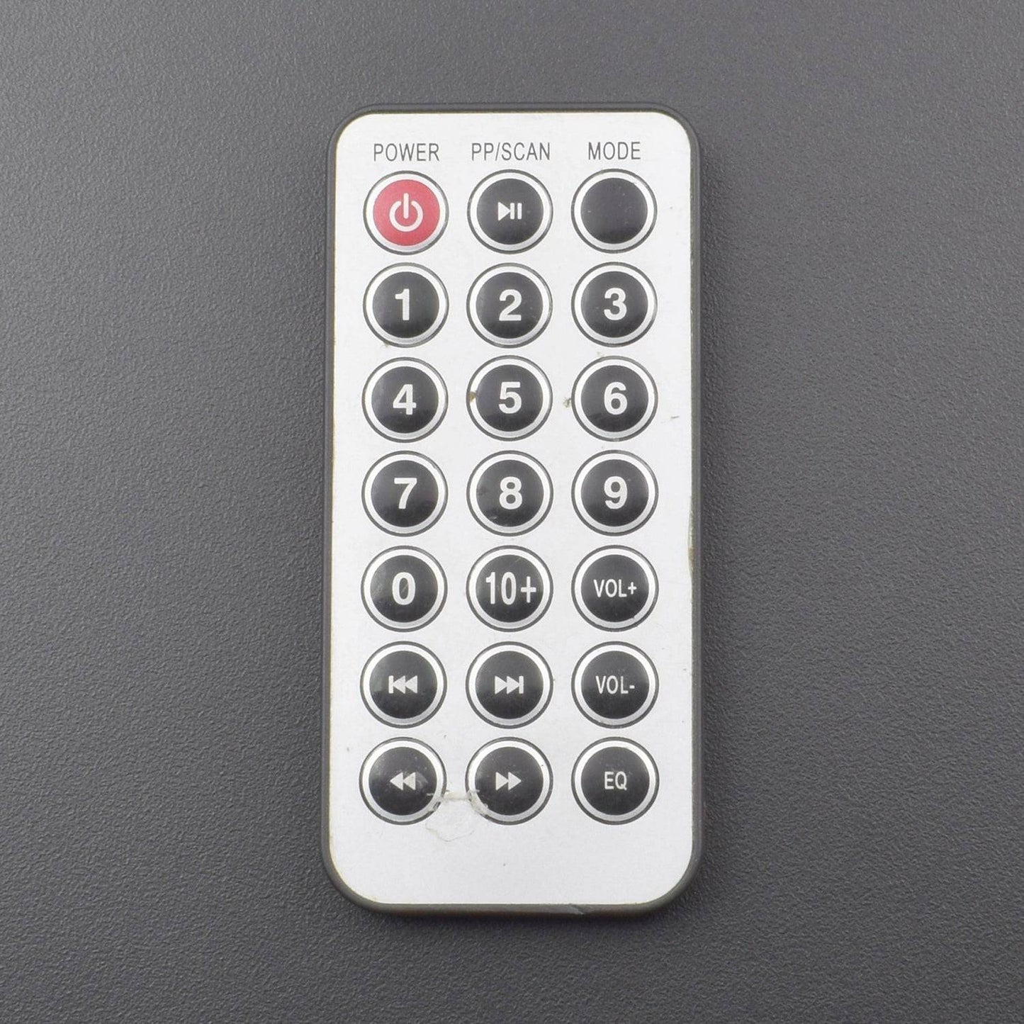
We have used button 1, button 2 and button 3 of an IR remote control for controlling FAN, BULB and AC respectively. The hex code value of the buttons after decoding.
CODE
This sketch read and decode the ir signal using the IRrecvDemo.ino available at the IR remote library. After that, we have written the code that receives the ir signal and matches using the switch statement. If button 2 is pressed then case 0x1FE50AF: relay1= relay1;// Button 1 break; The following part will execute and the variable relay2 will change from initial 0 to 1. Then we check using the if statement whether a relay2 variable is set or reset. According to that, we signal the relay to trigger ON or OFF.
WORKING
We are controlling the three home appliances using the IR remote control. This can be a Fan, Bulb, and AC. For controlling these home appliances we need three relays.
To get the remote control signals, we use the TSOP1738 ir receiver. This TSOP1738 ir receiver accepts only 38KHz ir signals coming from the IR remote control or tv remote control. The remote control button has some unique value or data to each button. The button value is sent in the form of ir signal at some frequency like 38KHz. The remote control frequency may depend on the remote control model. This transmission from remote has some form of modulation so the transmission range of remote control signal is quite far.
The main heart of arduino home automation project using IR remote control is understanding of decoding remote control signals.


