



- LCD Display Mode: STN, Positive, Transflective
- Display Color: Deep Blue/ Yellow Green
- Viewing Angle: 6H
- Driving Method : 1/16 duty, 1/5 bias
- Back Light : Yellow-Green LED backlight
- Outline Dimension: 803615.8 MAX
HARDWARE REQUIRED
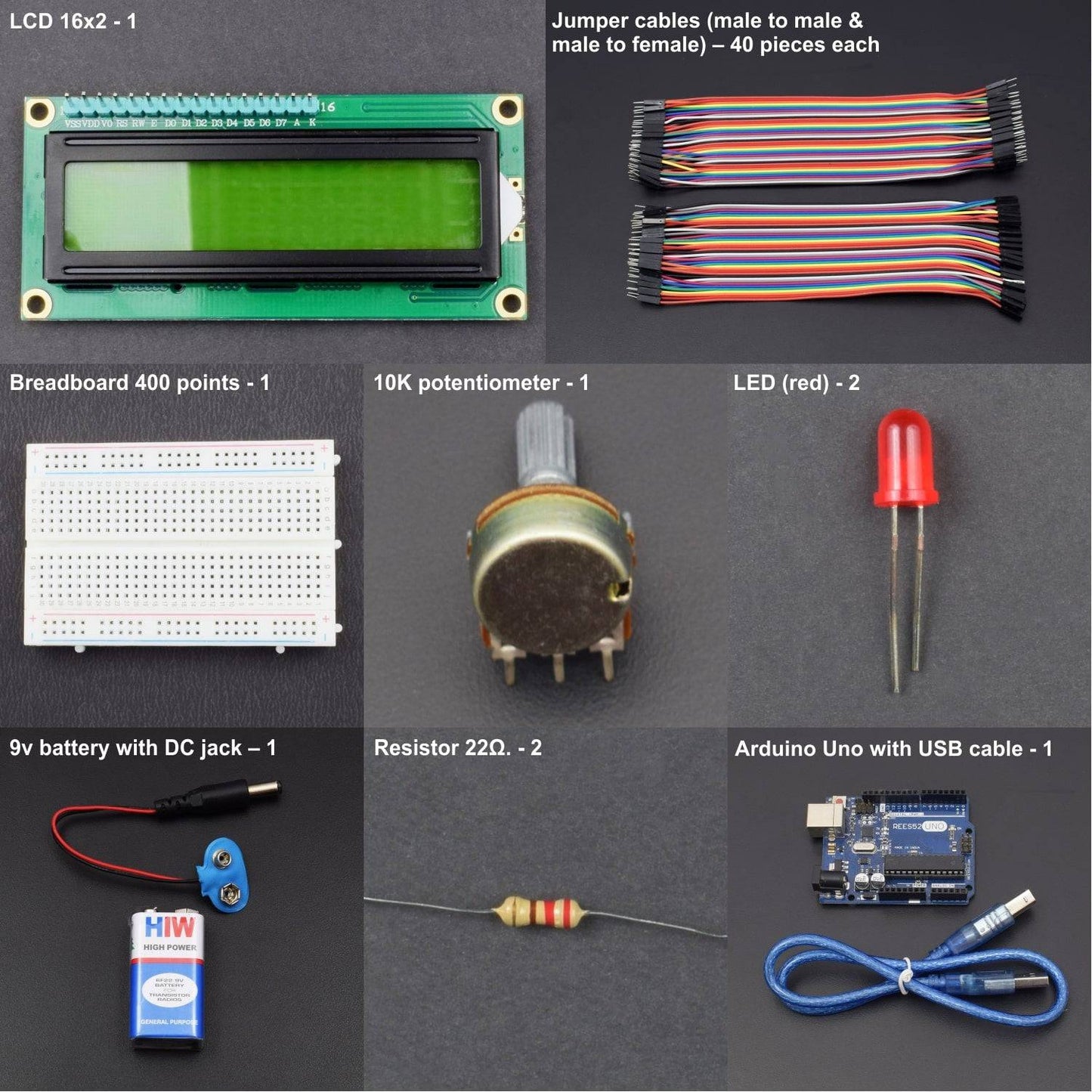
- Arduino Uno with USB cable - 1
- Resistor 22Ω. - 2
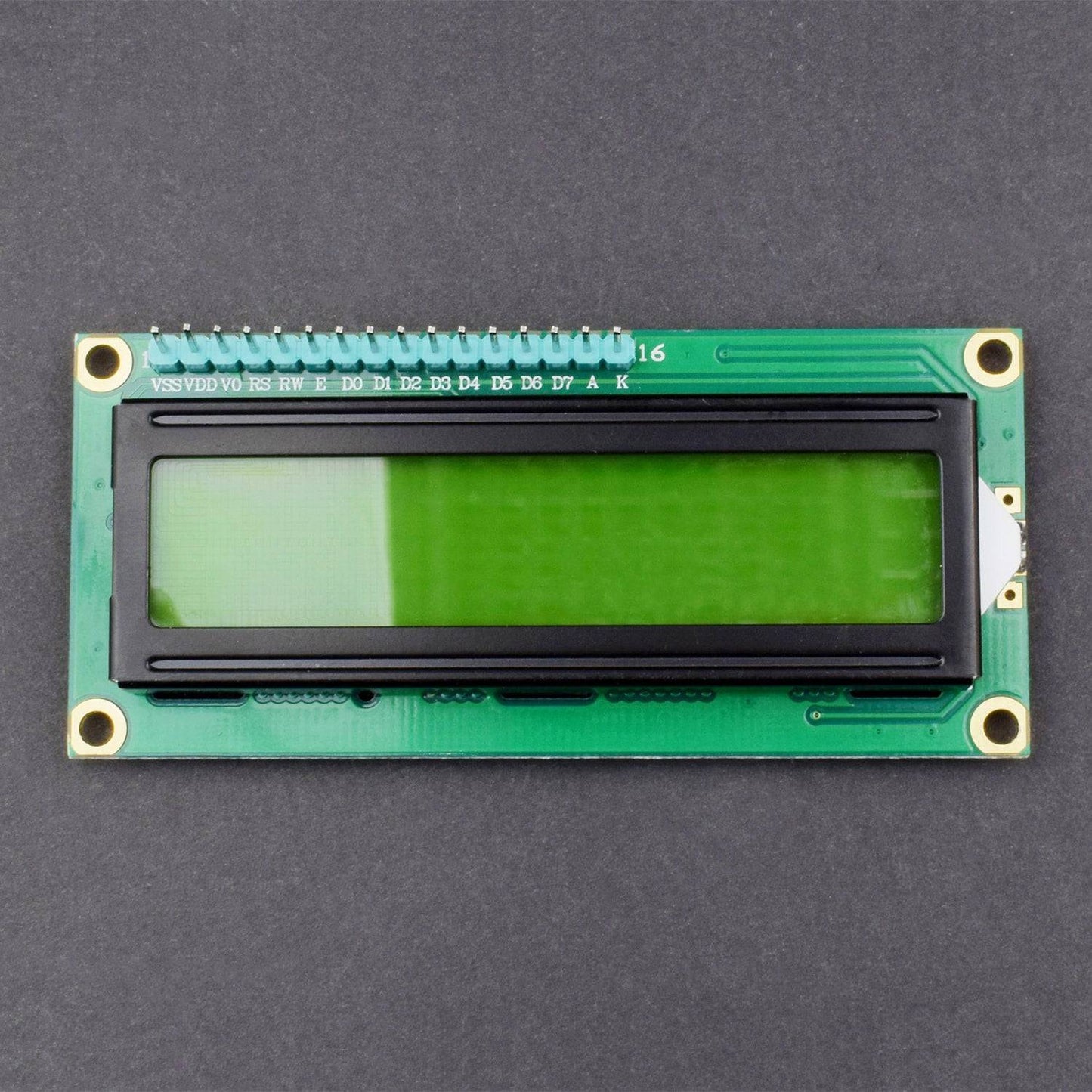
- LCD 16x2 - 1
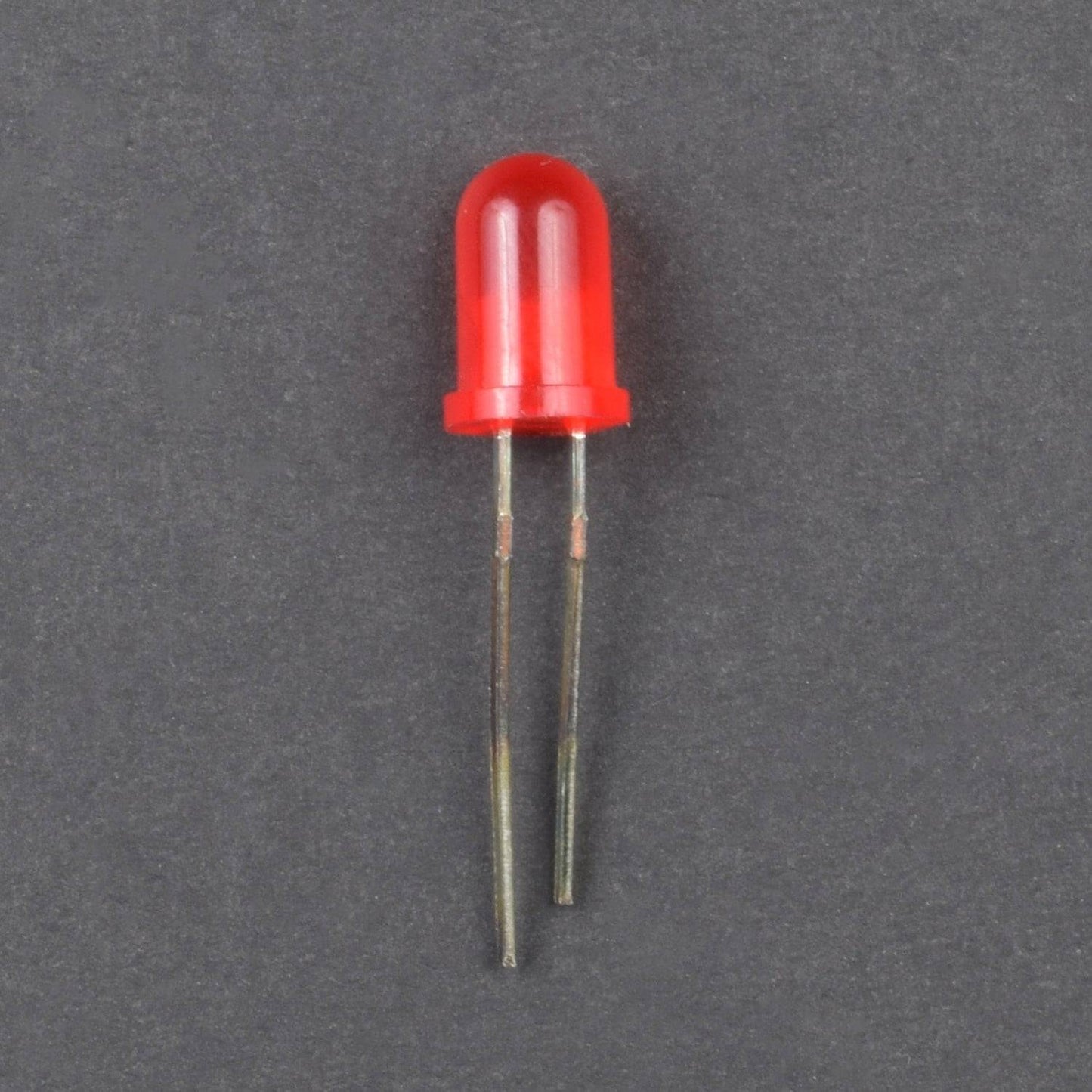
- LED (red) - 2
- 10K potentiometer - 1
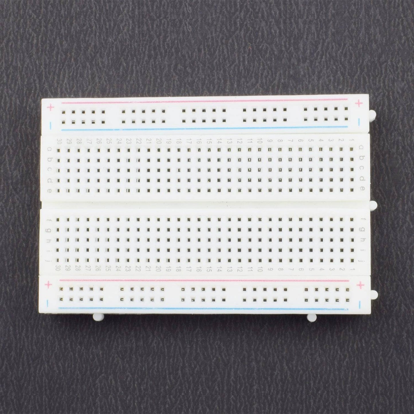
- Breadboard 400 points - 1
- Multimeter - 1(not included in kit)
- Jumper cables male to male – 40 piece
- Jumper wires MALE TO FEMALE – 40 piece
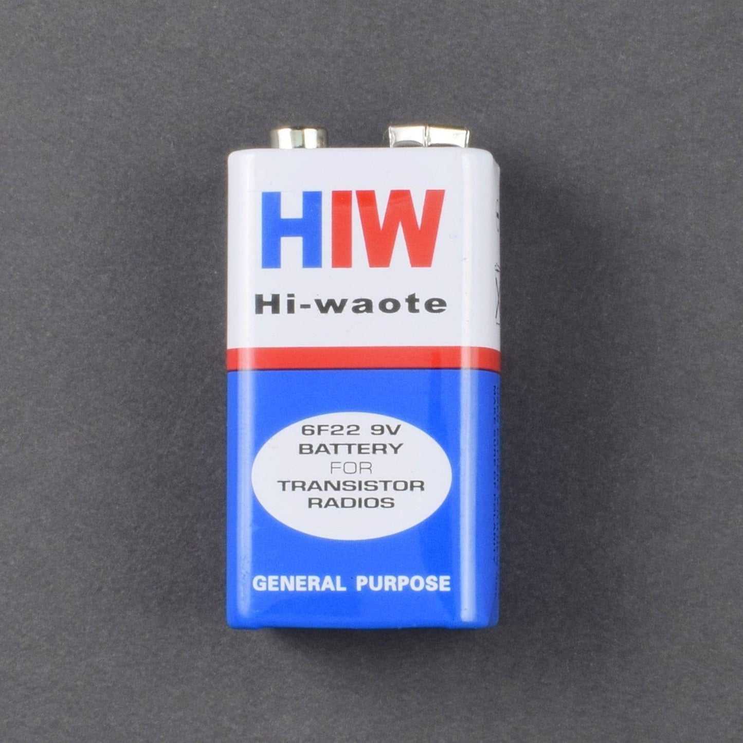
- 9v battery
- DC jack – 1
SPECIFICATION
- LCD
- LCD Display Mode: STN, Positive, Transflective
- Display Color: Deep Blue/ Yellow Green
- Viewing Angle: 6H
- Driving Method : 1/16 duty, 1/5 bias
- Back Light : Yellow-Green LED backlight
- Outline Dimension: 803615.8 MAX
CAUTIONS
• The LCD panel is made by glass. Any mechanical shock (eg. dropping from high place) will damage the LCD module.
• Do not add excessive force on the surface of the display, which may cause the Display color change abnormally.
• The polariser on the LCD is easily get scratched. If possible, do not remove the LCD protective film until the last step of installation.
• Never attempt to disassemble or rework the LCD module.
• Only Clean the LCD with Isopropyl Alcohol or Ethyl Alcohol. Other solvents (eg.water) may damage the LCD.
• When mounting the LCD module, make sure that it is free form twisting, warping and distortion.
• Ensure to provide enough space(with cushion) between case and LCD panel to prevent external force adding on it, or it may cause damage to the LCD or degrade the display result.
• Only hold the lCD module by its side. Never hold LCD module by add force on the heat seal ot TAB.
• Never add force to component of the LCD module. It may cause invisible damage or degrade of the reliability.
• LCD module could be easily damaged by static electricity. Be careful to maintain an optimum anti-static work environment to protect the LCD module.
• When peeling off the protective film from LCD, static charge may cause abnormal display pattern. It is normal and will resume to nomal in a short while.
• Take care and prevent get hurt by the LCD panel sharp edge.
• Never operate the LCD module exceed the absolute maximum ratings.
• Keep the signal line as short as possible to prevent noisy signal applying to LCD module.
• Never apply signal to the LCD module without power supply.
• IC chip(eg. TAB or COG) is sensitive to the light. Strong lighting environment could possibly cause malfunction. Light sealing structure casing is recommend.
• LCD module reliability may be reduced by temperature shock.
SOFTWARE REQUIRED
Arduino IDE ( programmable software for Arduino boards )
You can download the software from this link : https://www.arduino.cc/en/Main/Software
PIN DESCRIPTION
- 10 k Potentiometer

- 16*2 LCD shield

- LED

CIRCUIT DESCRIPTION

- The schematic diagram shows the connection of the Arduino Uno with LCD, resistor and LED. Arduino Uno is the power source of the all other components.
- The Arduino has analog and digital pins. The sensor circuit is connected to the analog inputs from which we get value of the voltage. The LCD is connect with the digital pins (7,8,9,10,11,12).
- The LCD has 16 pins the first two pins (VSS,VDD) and last two pins(Anode, Cathode) are connected to the gnd and 5v.
- The reset (RS) and enable (E) pins are connected to the Arduino digital pins 7 and 8. The data pins D4-D7 are connected to the digital pins of Arduino (9,10,11,12).
- The V0 pin is connected to the middle pin of pot. The red and black wires are 5v and gnd
Current Sensing Circuit:
This Ammeter circuit consists resistor and LED as load. Resistor is connected in series to the LED that current flows through the load and voltage drops is determined from the resistor. The terminal V1, V2 are going to connect with the analog input of the Arduino.
In the ADC of Arduino that coverts the voltage into 10 bit resolution numbers from 0-1023. So we need to covert it in voltage value using the programming. Before that we need to know the minimal voltage that ADC of Arduino can detect, that value is 4.88mV. We multiply the value from ADC with the 4.88mV and we get the actual voltage into the ADC.
Calculations:
The voltage value from the ADC of Arduino is ranges between 0-1023 and the reference voltage is ranges between 0-5v.
For example:
The value of the V1= 710, V2= 474 and R=22Ω, the difference between the voltages are 236. We convert it into voltage by multiply with 0.00488, then we get 1.15v. So the Voltage difference is 1.15v, by dividing it by 22 here we get the current value 0.005A. Here we have used the low value 22ohm resistor as current sensor. This is how we can measure the current using Arduino.
Principal:
All of us are well known of ohm’s law, It states that “the potential difference between two poles or terminals of an conductor is directly proportional to the amount of current pass through the same conductor” for constant of proportionality we use resistance, so here it comes the equation of ohm’s law.
V = IR
V = voltage across the conductor in Volt (v).
I = current pass through the conductor in Ampere (A).
R = resistance constant of proportionality in Ohm (Ω)
I = V / R
So in order to find out the current, we need some data:
- Voltage
- Resistance
We are going to build a series resistance along with the device. As we need to find voltage drop across the device, for that we need voltage readings before and after the voltage drop, that is possible in the resistance because of no polarity.

Like in the above diagram, we have to find the two voltages that are flowing across the resistor. The difference between the voltages (V1-V2) at the two ends of resistors gives us voltage drop
across the resistor (R) and we divide the voltage drop by the resistor value we get the current flow (I) through the device. That is how we can calculate the Current value passing through it, let’s gets into it practical implementation.
Arduino Code:
Complete code for arduino based ammeter to measure current, is given at the end of this article.
Arduino programming is almost same as like c programming, first we declare the header files. The header files call the file in the storage, like for the calculation I get the voltage values by using analogread function.
_
A temporary float variable is declared for holding voltage value like float temp_val. The value is multiplied with 0.00488 to get actual voltage difference then it is divided by resistor value to find the current flow. 0.00488v is the minimal voltage that the ADC of Arduino can detect.
CODE
/*
Technical Team , REES52
#include
LiquidCrystal lcd (7,8,9,10,11,12);
void setup() {
// put your setup code here, to run once:
Serial.begin(9600);
lcd.begin(16,2);
lcd.clear();
}
void loop() {
// put your main code here, to run repeatedly:
int voltage_value0 = analogRead(A0);
int voltage_value1 = analogRead(A1);
int subraction_value =(voltage_value0 - voltage_value1) ;
float temp_val = (subraction_value*0.00488);
float current_value = (temp_val/22);
Serial.print(current_value);
lcd.setCursor(0,0);
lcd.print("current value=");
lcd.setCursor(0,1);
lcd.print (current_value);
lcd.print("A");
delay(1000);
WORKING
After uploading the given code ,output will display on multimeter after measuring current


