


vendor-unknown
Making a Break failure Indicator using 555 Timer IC - KT954
Making a Break failure Indicator using 555 Timer IC - KT954
SKU:KT954
992 in stock
Couldn't load pickup availability
- For Bulk Order Click Here
- Need Customer Support?
- Free Delivery Above 999/-
Note: In case you receive a damaged or faulty product, please return it in the original box with all foam and packaging. Returns will not be accepted if further damage occurs due to improper packing.
For refund/return/replacement, call us at +91 95995 94520 or email us at support@rees52.com
Delivery Time
Delivery Time
- Delivery time with the Express Shipping option is 2-3 working days, and with the Standard Shipping option is 5-6 working days. It varies based on location, reliant on courier services.
- Delivery time if the order item is on Preorder Status is 15-20 working days.
COD (Cash on Delivery)
COD (Cash on Delivery)
- For COD you have to pay extra charges of Rs 350/- before the shipment. (We will share the company QR Code, UPI ID or Account details for the same)

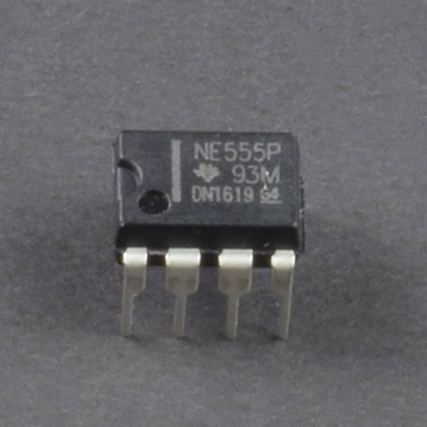
- 555 Timer ic - (1)
- 7805 Voltage regulator ic - (1)
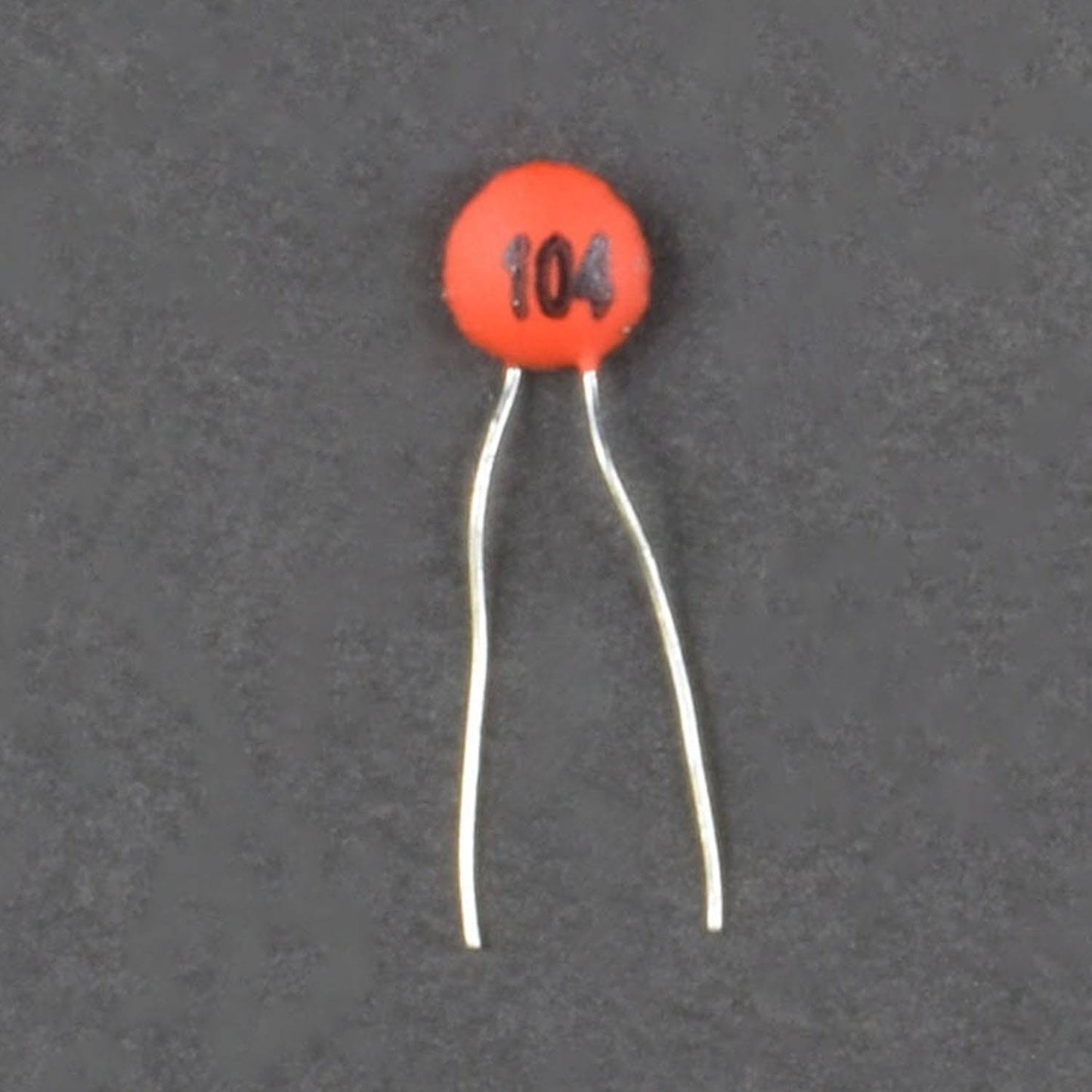
- Capacitor pack 1nf[102]-(2), 0.1uf[104]-(2), 1uf-(2)
- Resistor pack 1K ohm-(3), 440K ohm [330K+100K+10K]-(2)
- Transistor BC557 - 2
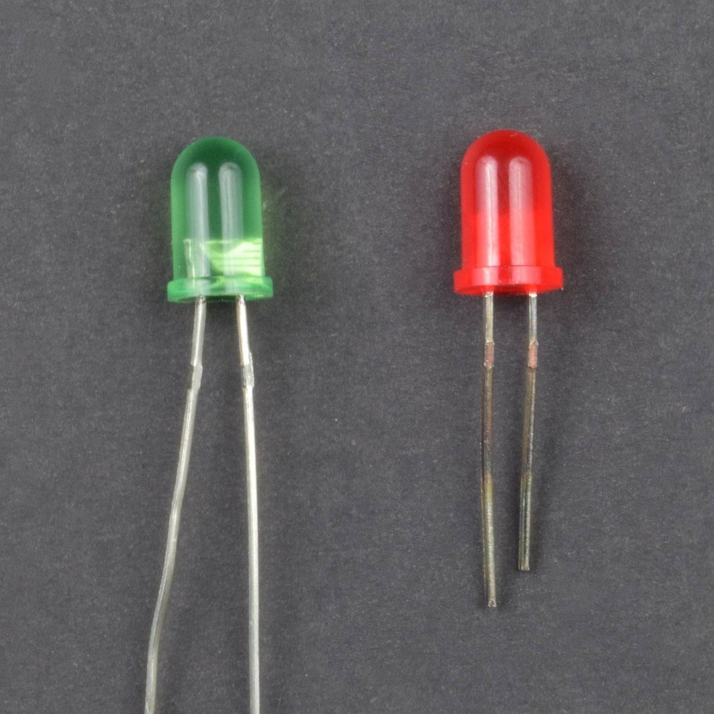
- Led 5mm (red and green ) - 2 pieces each
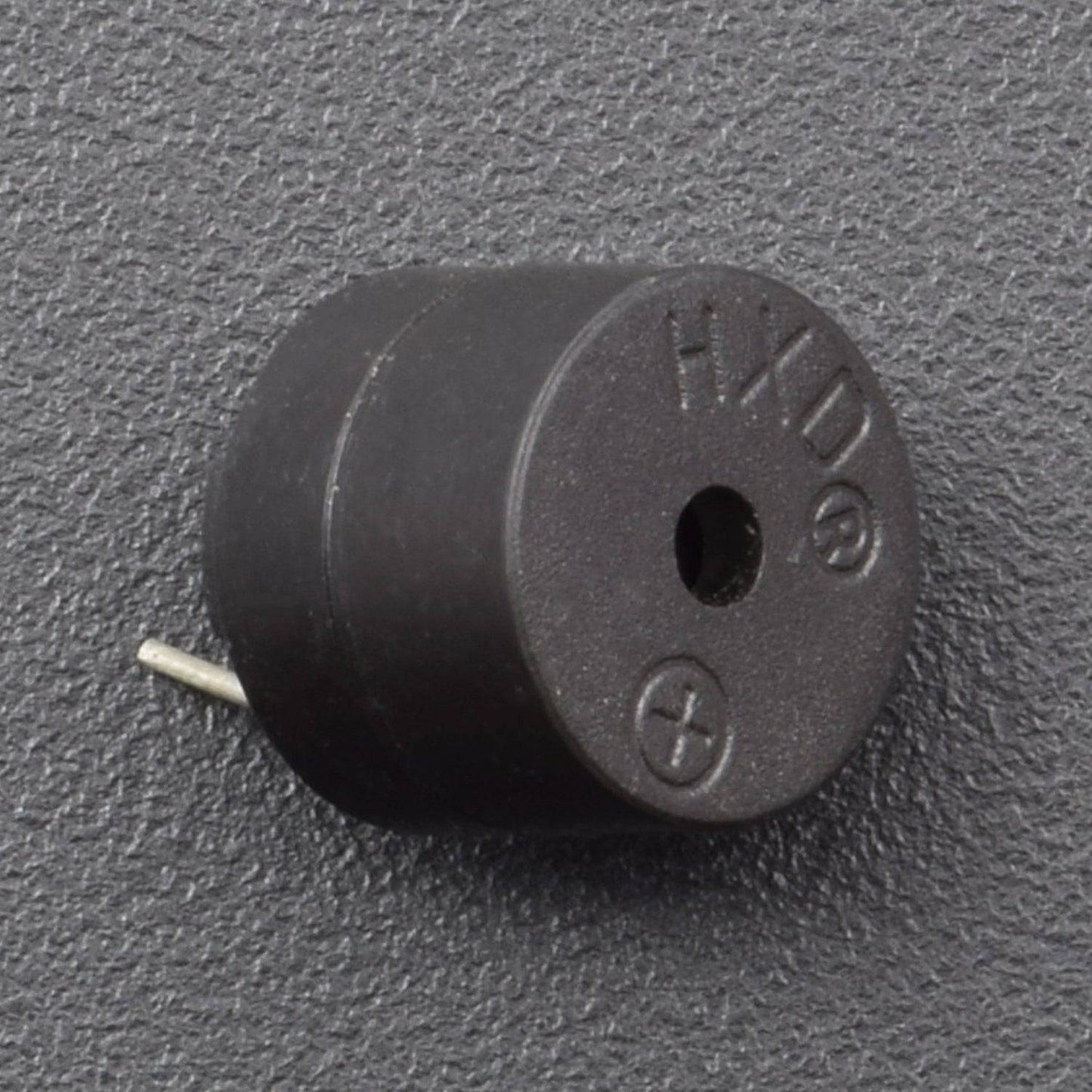
- B-10 buzzer-(1)
- Battery 9V - 1
- Battery snapper - 1
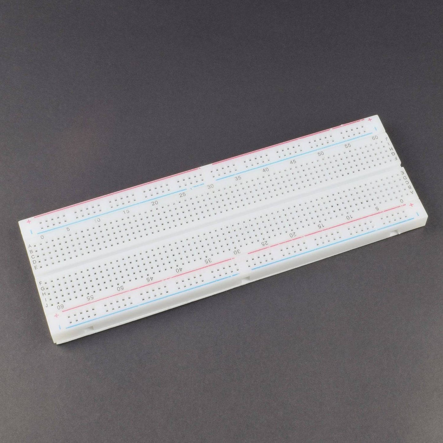
- Breadboard 840 points - 1
- Jumper wire(Male to Male) – 40 pcs
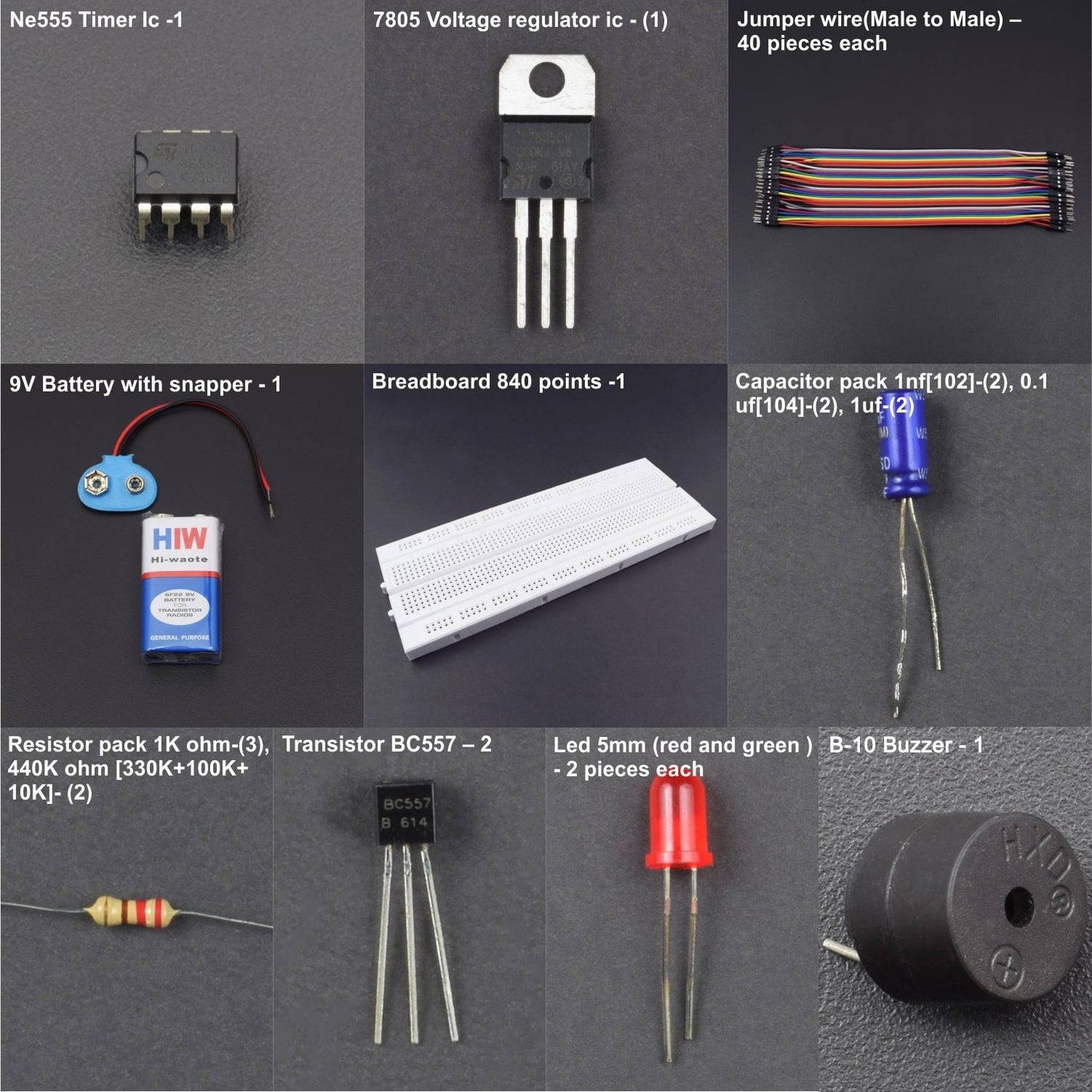
HARDWARE REQUIRED
- 555 Timer ic - (1)
- 7805 Voltage regulator ic - (1)
- Capacitor pack 1nf[102]-(2), 0.1uf[104]-(2), 1uf-(2)
- Resistor pack 1K ohm-(3), 440K ohm [330K+100K+10K]-(2)
- Transistor BC557 - 2
- Led 5mm (red and green ) - 2 pieces each
- B-10 buzzer-(1)
- Battery 9V - 1
- Battery snapper - 1
- Breadboard 840 points - 1
- Jumper wire(Male to Male) – 40 pcs
PIN DESCRIPTION
LED


555 TIMER IC


Pin |
Name |
Purpose |
1 |
GND |
Ground reference voltage, low level (0 V) |
2 |
TRIG |
The OUT pin goes high and a timing interval starts when this input falls below 1/2 of CTRL voltage (which is typically 1/3 Vcc, CTRL being 2/3 Vcc by default if CTRL is left open). In other words, OUT is high as long as the trigger low. Output of the timer totally depends upon the amplitude of the external trigger voltage applied to this pin. |
3 |
OUT |
This output is driven to approximately 1.7 V below +Vcc, or to GND. |
4 |
RESET |
A timing interval may be reset by driving this input to GND, but the timing does not begin again until RESET rises above approximately 0.7 volts. Overrides TRIG which overrides threshold. |
5 |
CTRL |
Provides “control” access to the internal voltage divider (by default, 2/3 Vcc). |
6 |
THR |
The timing (OUT high) interval ends when the voltage at threshold is greater than that at CTRL (2/3 Vcc if CTRL is open). |
7 |
DIS |
Open collector output which may discharge a capacitor between intervals. In phase with output. |
8 |
Vcc |
Positive supply voltage, which is usually between 3 and 15 V depending on the variation. |
BC557 TRANSISTOR


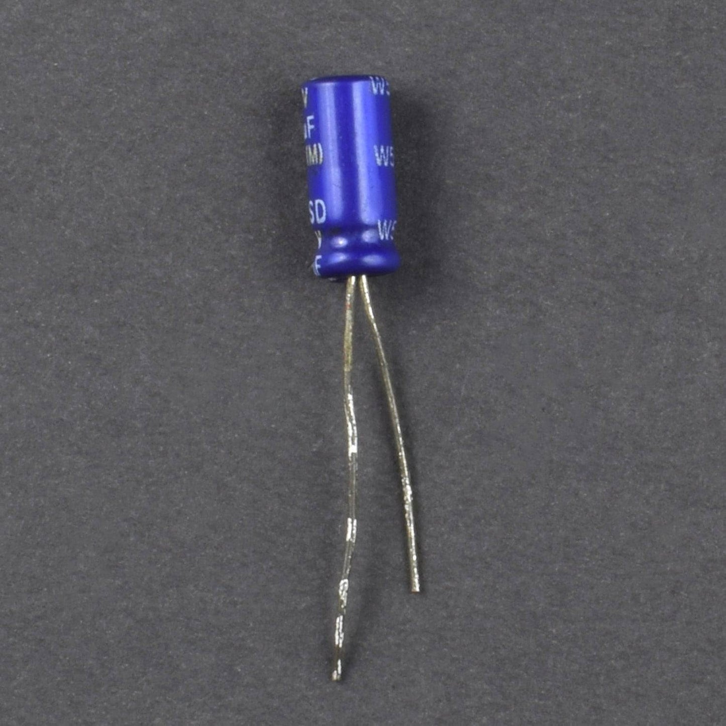
47UF CAPACITOR


The Shorter Terminal is negative and the longer Terminal is Positive
7805 VOLTAGE REGULATOR


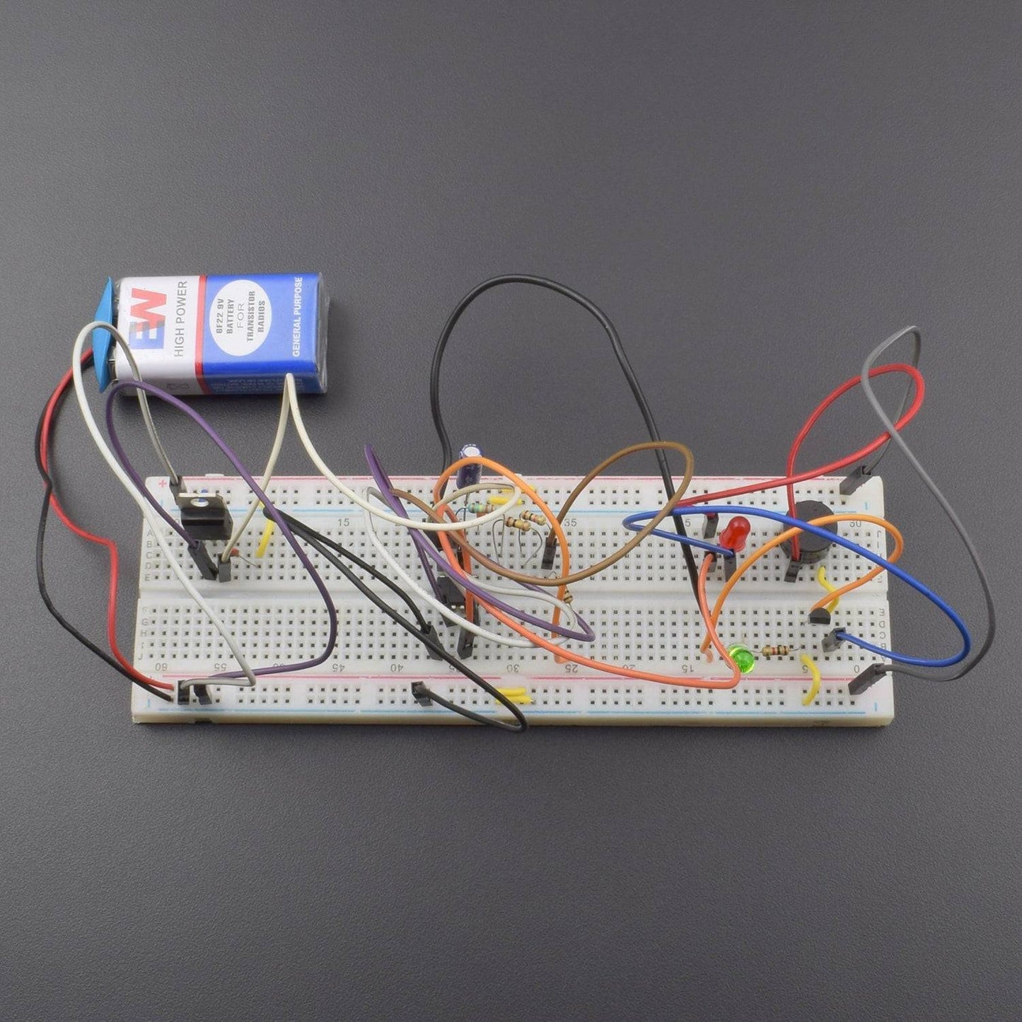
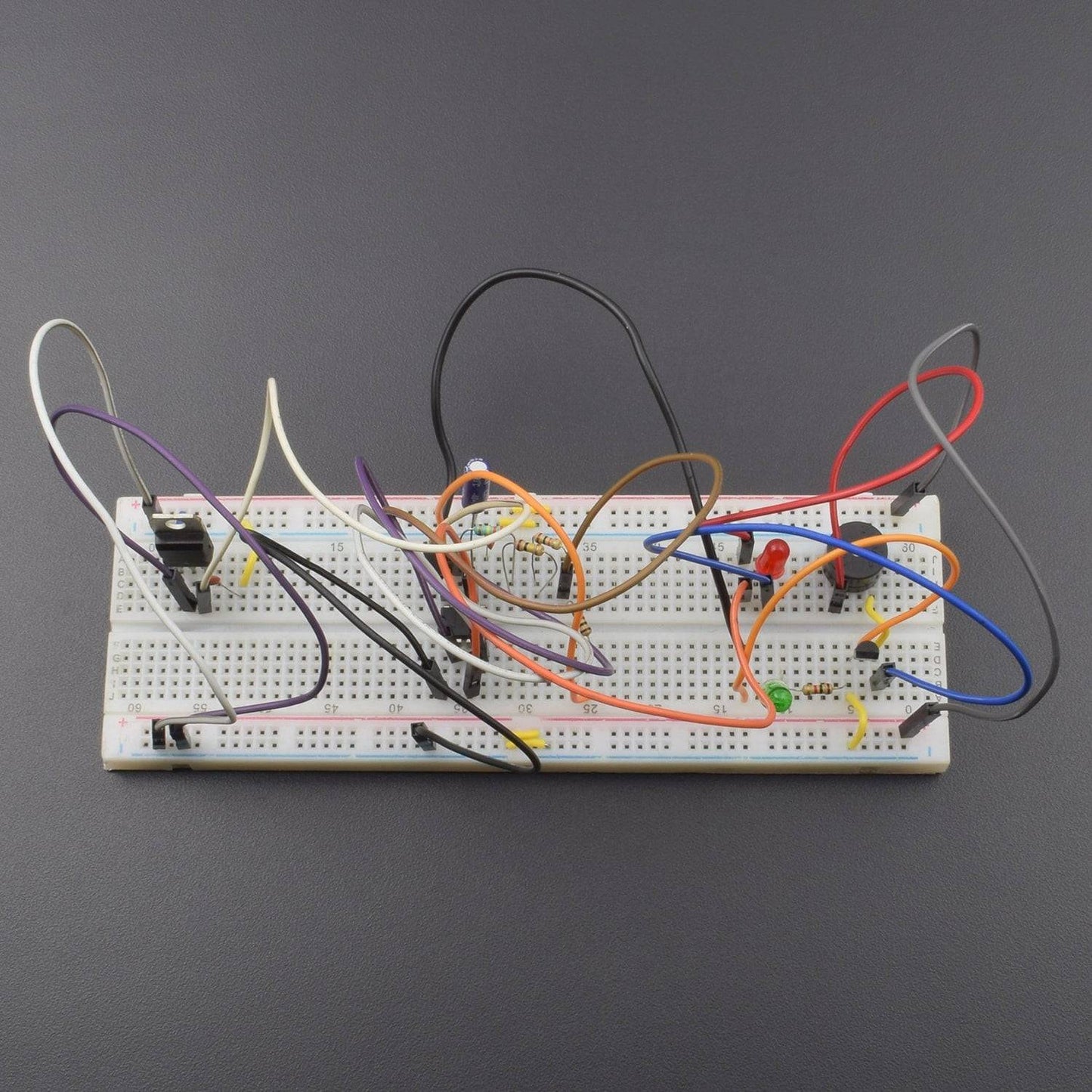
CIRCUIT CONNECTION

- Connect 7805 and 555 timer ic on the breadboard.
- Connect pin 1 of 7805 ic to the positive rail, pin 2 to GND and pin 3 to the pin 8 of 555 timer ic.
- 7805 ic 3rd leg is connected to the 1nF(102) ceramic capacitor and capacitor 2nd leg is GND
- 555 ic pin no 1 is GND and pin no 2 is connected to the pin no 6 and pin no 6 to connected 1uF capacitor positive leg and another leg is GND
- 555 ic pin no 6 to connected 440K ohm(330K+100K+10K) resistor and resistor 2nd leg is connected to the 555 ic pin no 7
- 4440K ohm resistor 2nd leg to connect to the 1K ohm resistor and 1K ohm resistor 2nd leg is connected to the 555 ic pin no 8
- 555 ic pin no 5 to connected 0.1uF(104) ceramic capacitor and capacitor 2nd leg is GND
- 555 ic pin no 4 is connected to the pin no 8.
- BC 557 transistor is connected to the breadboard and 1st leg is GND and 1st leg to connected 1K ohm resistor and 1k ohm resistor 2nd leg is connected to the led(green) negative leg and led positive leg is connected to the transistor 2nd leg.
- Buzzer connected to the breadboard and buzzer negative leg connected to the transistor 3rd leg and transistor 3rd led is connected to the led(red) negative leg
- led(red) positive leg is connected to the buzzer positive leg and led(red) positive leg is connected to the 555 ic pin no 3
- Break wire 1st leg is connected to the led(green) positive leg and brake wire 2nd leg is connected to the 555 ic pin no 8.
- Breadboard connection for positive to positive and negative to negative connection
WORKING
Automobiles have been the primary mode of transportation for most of us and we depend on them for our day to day commute. Unfortunately, there are lots of mishaps that could occur while driving an automobile and Brake Failures are one such case. Of course, accidents cannot be avoided sometimes but they can sure be prevented by taking some preventive measures. In this project, we will build a Circuit that can be attached to our Vehicles which will monitor the brake of our vehicle and provide us audio-visual feedback if the brake fails.
Most economical vehicles depend on wire braking mechanism to apply brakes on the vehicle. This mechanism involves a Brake wire which runs from the brake lever to the braking mechanism set-up of the vehicle. It is this wire that gets pulled when we apply brakes to stop our vehicle. After a long use and tear these wires might get worn out and get cut at one point of time which eventually will cause brake failure. So we will build a circuit that will monitor the continuity of this wire, the circuit will glow a green colour LED if everything is fine, but is the wire fails the circuit will blink a red color LED also will beep a buzzer to alert the rider. Let us see how we can build this project.