


REES52
Make an IoT-Based Tilt Switch Alarm Using Tilt Switch and Buzzer with NodeMCU ESP8266-12e Wi-Fi Board - KT567
Make an IoT-Based Tilt Switch Alarm Using Tilt Switch and Buzzer with NodeMCU ESP8266-12e Wi-Fi Board - KT567
SKU:KT567
49 in stock
Couldn't load pickup availability
- For Bulk Order Click Here
- Need Customer Support?
- Free Delivery Above 999/-
Note: In case you receive a damaged or faulty product, please return it in the original box with all foam and packaging. Returns will not be accepted if further damage occurs due to improper packing.
If you order a product that is currently in Preorder, and the price of that item increases in the future, you will be required to pay the difference in price.
For refund/return/replacement, call us at +91 95995 94520 or email us at support@rees52.com
Delivery Time
Delivery Time
- Delivery time with the Express Shipping option is 2-3 working days, and with the Standard Shipping option is 5-6 working days. It varies based on location, reliant on courier services.
- Delivery time if the order item is on Preorder Status is 15-20 working days.
COD (Cash on Delivery)
COD (Cash on Delivery)
- For COD you have to pay extra charges of Rs 350/- before the shipment. (We will share the company QR Code, UPI ID or Account details for the same)
INRODUCTION
In this project, we are making an IOT-based Tilt Switch Alarm using a Tilt Switch Sensor and ESP8266-12e Wi-fi Board.
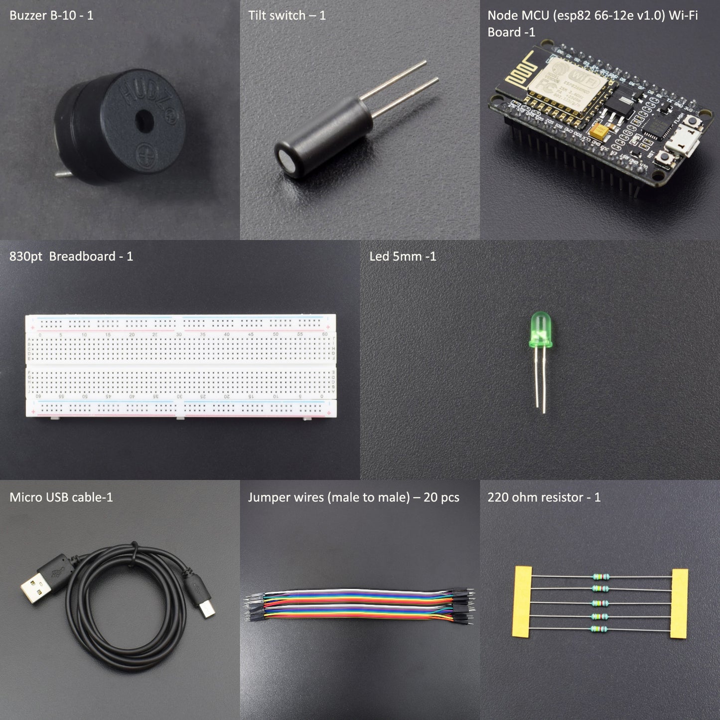
HARDWARE REQUIRED
- Node MCU (esp82 66-12e v1.0) Wi-Fi Board -1pc
- NodeMcu USB Cable - 1pc
- Tilt Switch -1pc
- Jumper Wires (male to male) – 20 pcs
- 830 pt. Breadboard - 1pc
- Led 5mm -1pc
- 220-ohm Resistor – 1pc
- Buzzer B-10 -1pc
SOFTWARE REQUIRED
Arduino IDE 1.8.10 (programmable platform for Arduino)
Click here to download the software

SPECIFICATIONS
NodeMCU ESP8266 CP2102 Module:
- ESP8266 CP2102 NodeMCU LUA ESP-12E WIFI Serial Wireless Module
- Built-in Micro-USB, with flash and reset switches, easy to program
- Full I/O port and Wireless 802.11 supported, direct download, no need to reset
- Arduino compatible works great with the latest Arduino IDE/Mongoose IoT/Micro Python

WARNING
The ESP8266 requires a 3.3v power supply and 3.3v logic levels for communication. The GPIO pins are not 5v-tolerant! If you want to interface the board with 5v (or higher) components, you must do some level shifting.
Tilt Switch Sensor:
A Tilt Sensor switch is an electronic device that detects the orientation of an object and gives its output High or Low accordingly. It has a mercury ball inside it that moves and makes the circuit. So the tilt sensor can turn on or off the circuit based on the orientation.
The tilt sensor is cylindrical and contains a free conductive rolling ball inside with two conductive elements (poles) beneath.
Here’s how it works:
- When the sensor is completely upright, the ball falls to the bottom of the sensor and connects the poles, allowing the current to flow.
- When the sensor is tilted, the ball doesn’t touch the poles, the circuit is open, and the current doesn’t flow.

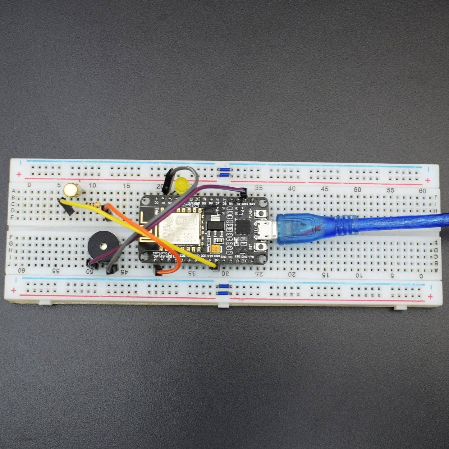
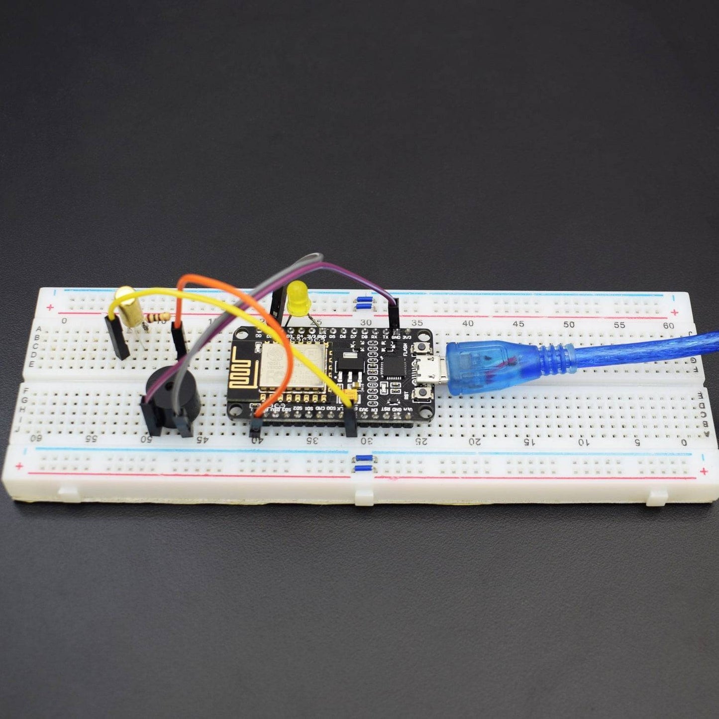
CIRCUIT CONNECTION
- Connect one terminal of the Tilt Switch to the “Vin” pin of the NodeMCU ESP8266-12e Wi-Fi Module.
- Connect another terminal of the Tilt Switch to the A0 pin and the GND pin of NodeMCU ESP8266-12e Wi-Fi Module via a 220-ohm resistor.
- Connect the LED ground pin to the GND pin of the NodeMCU ESP8266-12e Wi-Fi Module.
- Connect the LED positive terminal to the D2(GPIO4) pin of NodeMCU ESP8266-12e Wi-Fi Module.
- Connect the Buzzer GND pin to the GND pin of NodeMCU ESP8266-12e Wi-Fi Module.
- Connect Buzzer’s Positive pin to D1(GPIO5) pin of NodeMCU ESP8266-12e Wi-Fi Module.

CODE
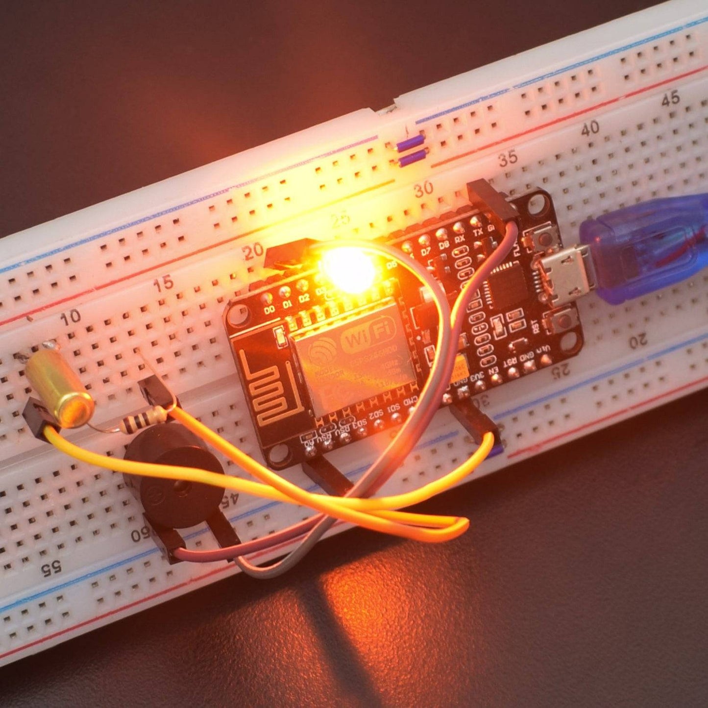
WORKING AND OUTPUT
Welcome to the IoT-based Tilt Switch Alarm circuit. You can use this circuit with many rotation-based applications. As we know, this sensor produces an electrical signal that is proportional to the degree of inclination with respect to one or more axes. These sensors play a very important role in several applications such as off-road vehicles, portable computers, robotics devices, aviation instruments, etc.
In this project, when the device gets power and is in its upright position, the rolling ball settles at the bottom of the sensor to form an electrical connection between the two end terminals of the sensor. Next, the circuit becomes a short circuit, and the LED gets sufficient current, and it will glow, and the buzzer starts to sound. If the circuit gets tilted so that the rolling ball doesn’t settle at the bottom of the sensor with the electrical conduction path, then the circuit becomes open. And led and buzzer should be activated until the switch ball doesn’t settle at the bottom. This is about the circuit operation.
You can check the status in the serial monitor.
