


vendor-unknown
Make an IoT based Gas level controlling system using MQ-2 Gas Sensor module and led with NodeMCU ESP8266-12e Board - KT566
Make an IoT based Gas level controlling system using MQ-2 Gas Sensor module and led with NodeMCU ESP8266-12e Board - KT566
SKU:KT566
Low stock: 7 left
Couldn't load pickup availability
- For Bulk Order Click Here
- Need Customer Support?
- Free Delivery Above 999/-
Note: In case you receive a damaged or faulty product, please return it in the original box with all foam and packaging. Returns will not be accepted if further damage occurs due to improper packing.
If you order a product that is currently in Preorder, and the price of that item increases in the future, you will be required to pay the difference in price.
For refund/return/replacement, call us at +91 95995 94520 or email us at support@rees52.com
Delivery Time
Delivery Time
- Delivery time with the Express Shipping option is 2-3 working days, and with the Standard Shipping option is 5-6 working days. It varies based on location, reliant on courier services.
- Delivery time if the order item is on Preorder Status is 15-20 working days.
COD (Cash on Delivery)
COD (Cash on Delivery)
- For COD you have to pay extra charges of Rs 350/- before the shipment. (We will share the company QR Code, UPI ID or Account details for the same)

Kit Includes
- MQ2 Gas Module - 1
- LEDs 5mm (Red & Green) - 2
- Node MCU (esp82 66-12e v1.0) Wi-Fi Board -1
- NodeMcu USB cable - 1
- Jumper Wires (male to male) – 20 pcs each
- 830 pt. breadboard - 1
Introduction
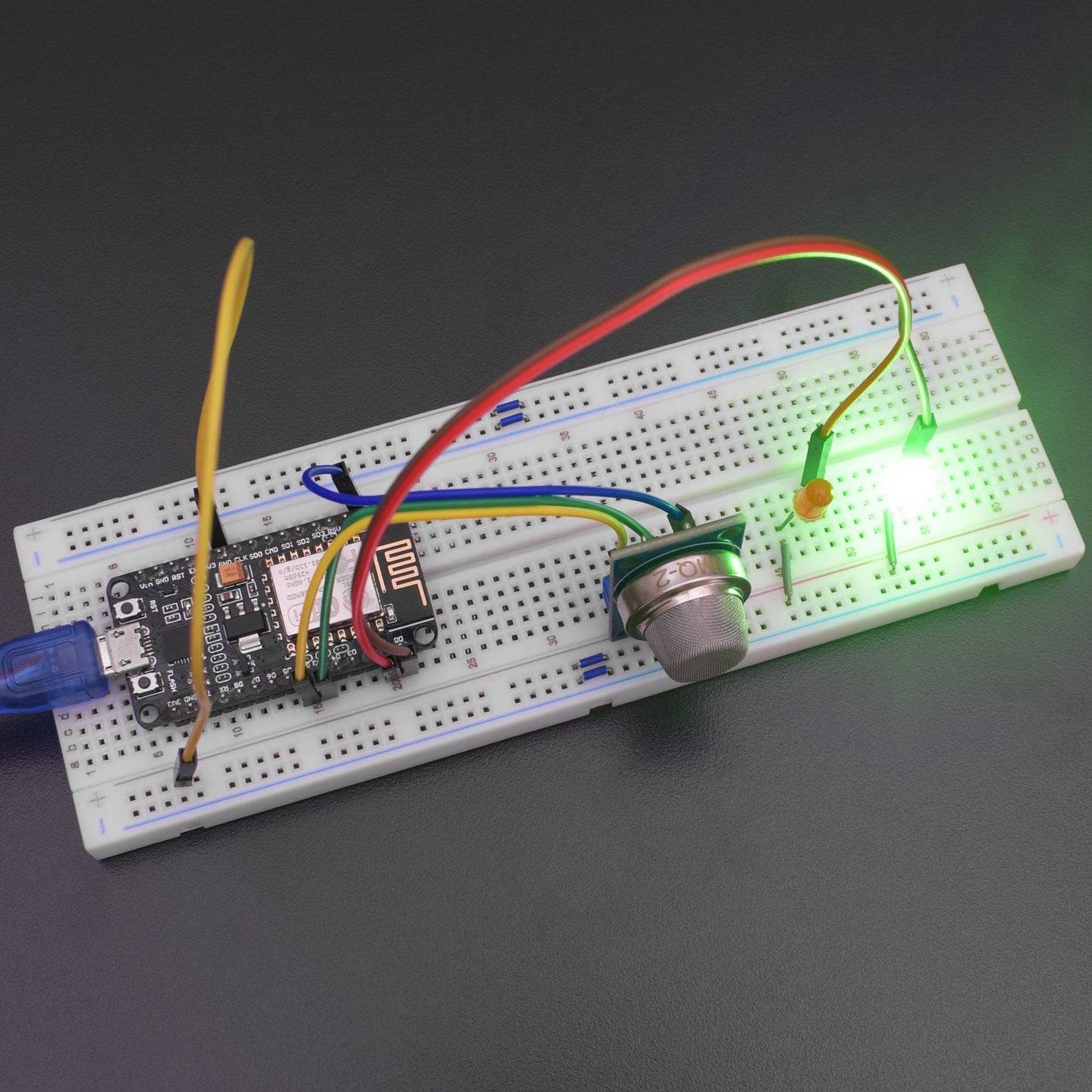
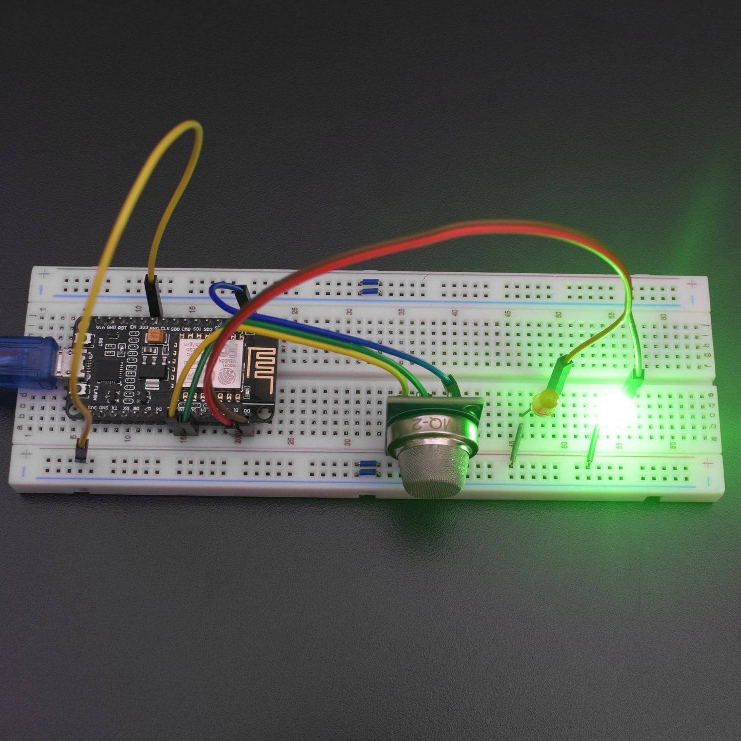
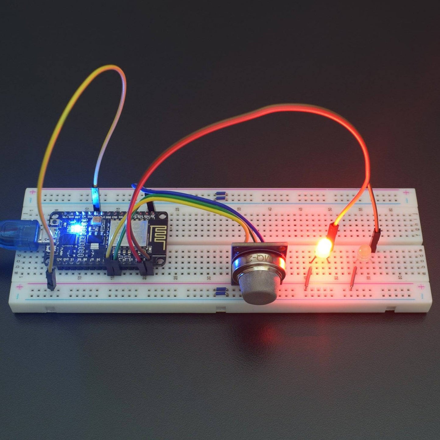
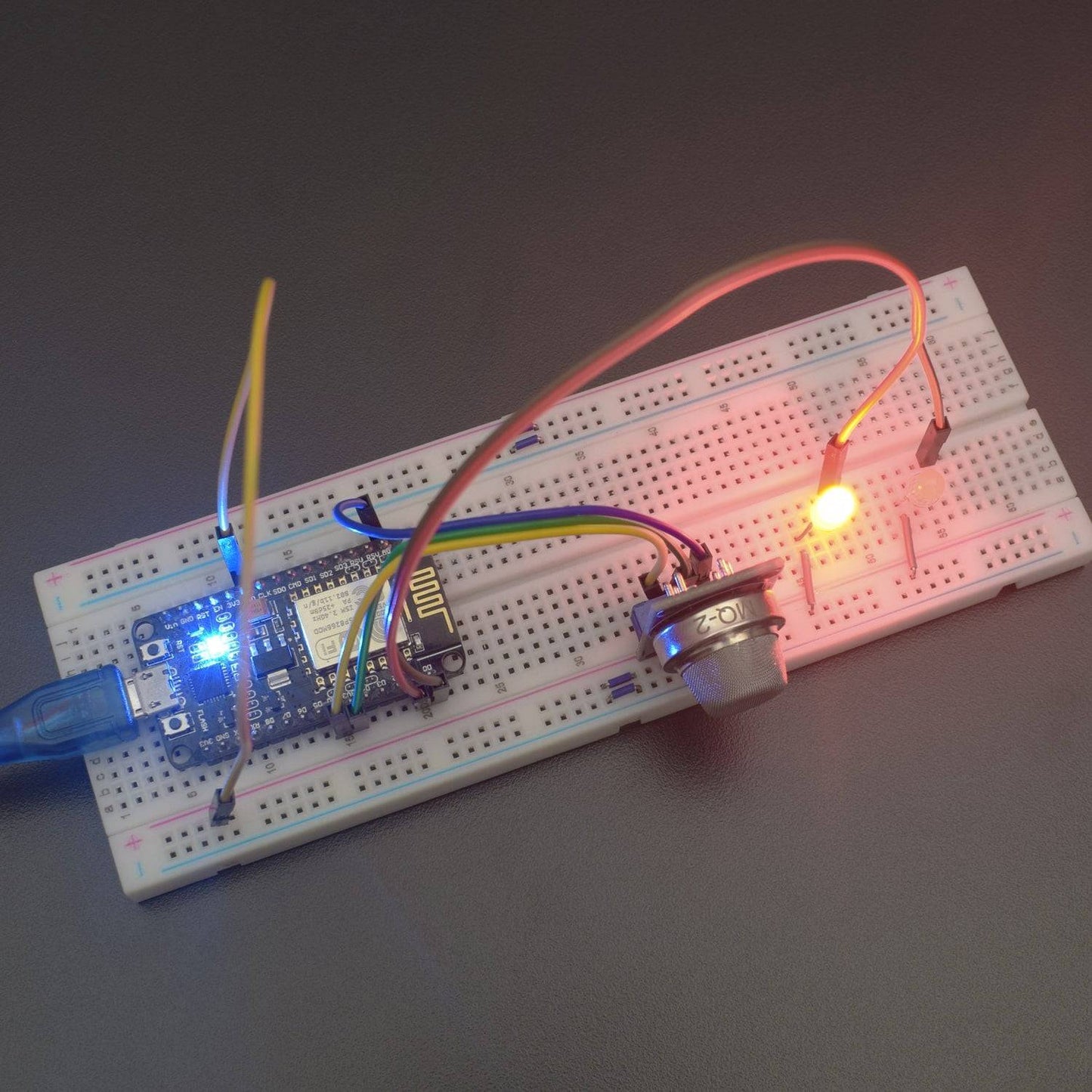
In this project, we have used to design an IOT based Gas level sensor using Node MCU by interfacing with Blynk application and level for gas will be shown on Leds. If level increases to high level then red led will glow and if decreases to low level then the green led will glow.
HARDWARE REQUIRED
- MQ2 Gas Module - 1
- LEDs 5mm (Red & Green) - 2
- Node MCU (esp82 66-12e v1.0) Wi-Fi Board -1
- NodeMcu USB cable - 1
- Jumper Wires (male to male) – 20 pcs each
- 830 pt. breadboard - 1
SOFTWARE REQUIRED
Arduino IDE 1.8.10 (programmable platform for Arduino)
Click To Download: https://www.arduino.cc/en/Main/Software

SPECIFICATIONS
NodeMCU ESP8266 CP2102 NodeMCU WIFI Serial Wireless Module
The development board equips the ESP-12E module containing ESP8266 chip having Tensilica Xtensa® 32-bit LX106 RISC microprocessor which operates at 80 to 160 MHz adjustable clock frequency and supports RTOS.
- Operating Voltage: 2.5V to 3.6V
- On-board 3.3V 600mA regulator
- 80mA Operating Current
- 20 µA during Sleep Mode
- ESP8266 CP2102 NodeMCU LUA ESP-12E WIFI Serial Wireless Module
- Built-in Micro-USB, with flash and reset switches, easy to program
- Full I/O port and Wireless 802.11 supported, direct download no need to reset
- Arduino compatible works great with the latest Arduino IDE/Mongoose IoT/Micro python

WARNING
The ESP8266 requires a 3.3V power supply and 3.3V logic levels for communication. The GPIO pins are not 5V-tolerant! If you want to interface the board with 5V (or higher) components, you’ll need to do some level shifting.
MQ-2 Gas Sensor Module
- Operating Voltage is +5V
- Can be used to Measure or detect LPG, Alcohol, Propane, Hydrogen, CO and even methane
- Analog output voltage: 0V to 5V
- Digital Output Voltage: 0V or 5V (TTL Logic)
- Preheat duration 20 seconds
- Can be used as a digital or analog sensor
- The Sensitivity of Digital pin can be varied using the potentiometer
_1.jpg)
Pin No: |
Pin Name: |
Description |
1 |
Vcc |
This pin powers the module, typically the operating voltage is +5V |
2 |
Ground |
Used to connect the module to system ground |
3 |
Digital Out |
You can also use this sensor to get digital output from this pin, by setting a threshold value using the potentiometer |
4 |
Analog Out |
This pin outputs 0-5V analog voltage based on the intensity of the gas |
LIBRARY REQUIRED
Blynk -


CIRCUIT CONNECTION
- Connect MQ2 Module “A0” pin to node MCU pin A0.
- Connect MQ2 Module “V” pin to node MCU pin 3v3.
- Connect MQ2 Module ground to node MCU ground.
- Connect the positive terminal of 1st Led to node MCU Pin D0.
- Connect the positive terminal of 2nd Led to node MCU Pin D1.
- Connect both negative terminals of LEDs to the GND rail on the breadboard which is connected to the GND pin of NodeMCU.

CODE
Click to see the code
https://drive.google.com/open?id=1C7d47lML6zx8tgg7Fe_QA5zebh3HBVct
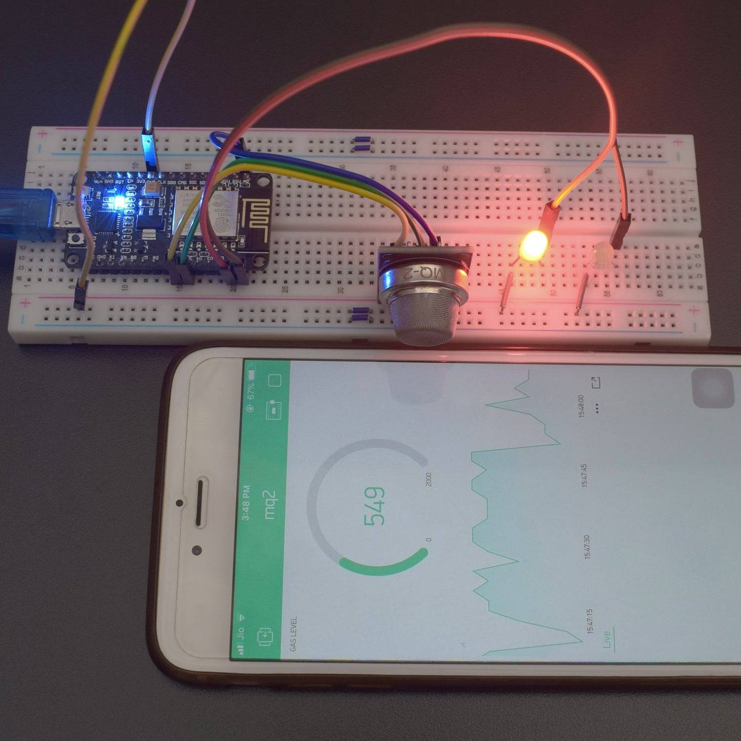
WORKING AND OUTPUT
Welcome to the IoT based Gas Detector indicator circuit.
- To connect with Blynk Application. First, you need to create a new project An AUTH token will be sent to your registered Email ID which you need to note down. You need to insert the key in the given code.

Open the Widget Box and select the Labeled value widget option from the Dropdown list

- Click on the plus icon and select Labelled value for The gas level.
- define the pins in V1.

- Change the min to 0 Max to 1000.
- Click on the plus icon to add widget and select a super chart to see the graphical measurement for gas value. Now, press the upload button.
- After calculating the MQ2 Gas Sensor Module, the values will be shown on the graphical interface.


Click to watch the tutorial
For more tutorials subscribe our channel REES52 on YouTube