


vendor-unknown
Make an Electronics Siren Circuit using 2 Transistors - KT952
Make an Electronics Siren Circuit using 2 Transistors - KT952
SKU:KT952
1000 in stock
Couldn't load pickup availability
- For Bulk Order Click Here
- Need Customer Support?
- Free Delivery Above 999/-
Note: In case you receive a damaged or faulty product, please return it in the original box with all foam and packaging. Returns will not be accepted if further damage occurs due to improper packing.
If you order a product that is currently in Preorder, and the price of that item increases in the future, you will be required to pay the difference in price.
For refund/return/replacement, call us at +91 95995 94520 or email us at support@rees52.com
Delivery Time
Delivery Time
- Delivery time with the Express Shipping option is 2-3 working days, and with the Standard Shipping option is 5-6 working days. It varies based on location, reliant on courier services.
- Delivery time if the order item is on Preorder Status is 15-20 working days.
COD (Cash on Delivery)
COD (Cash on Delivery)
- For COD you have to pay extra charges of Rs 350/- before the shipment. (We will share the company QR Code, UPI ID or Account details for the same)

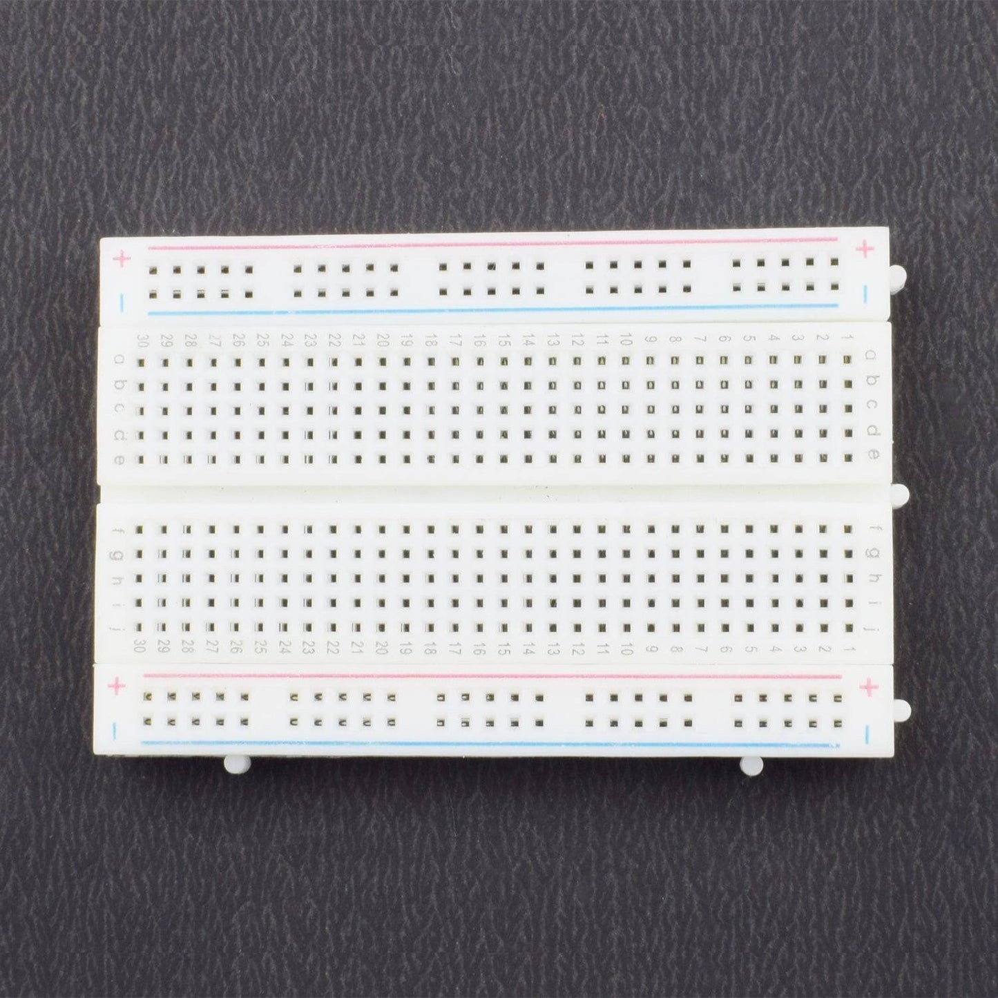
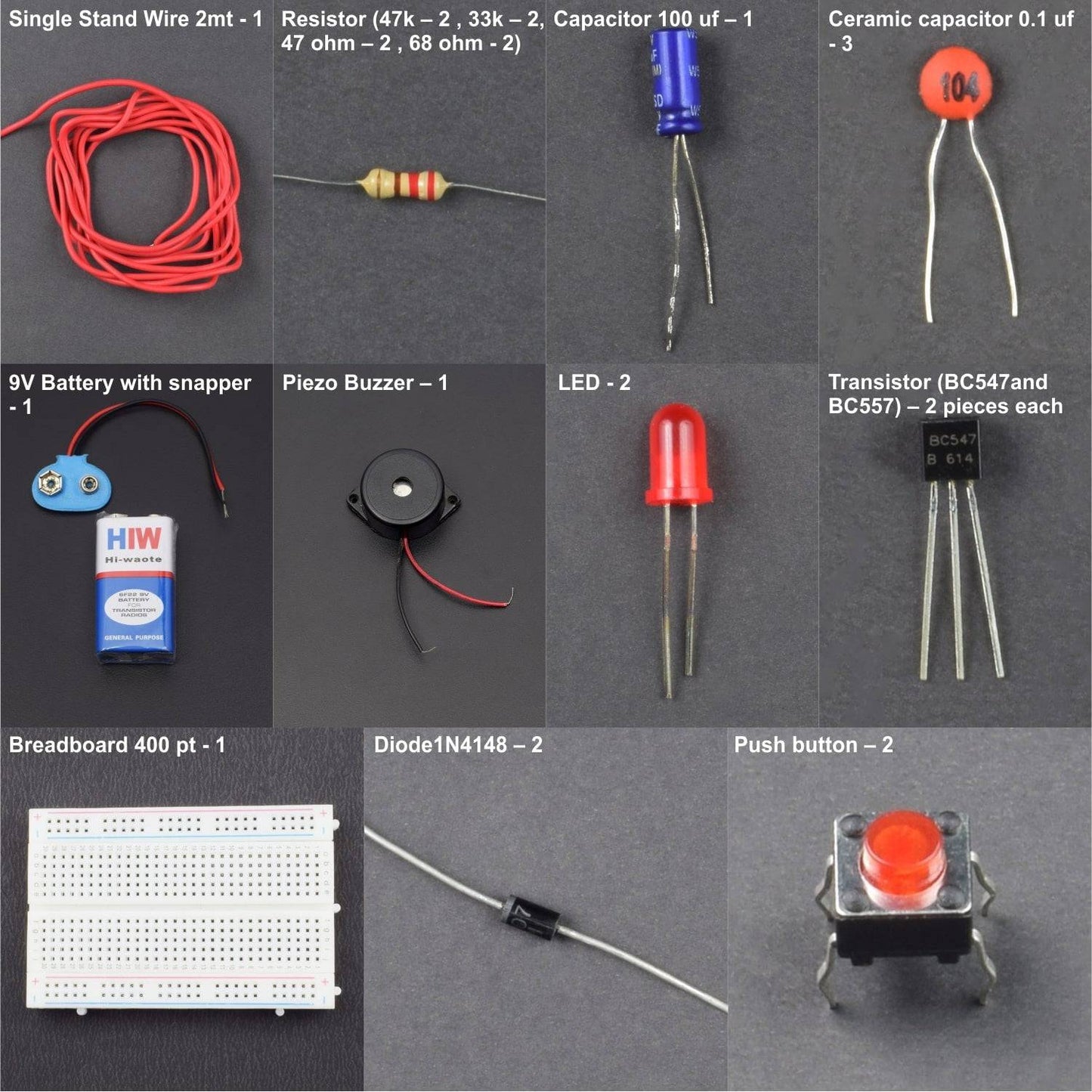
- Breadboard 400 points – 1
- 9v battery -1
- battery snapper – 1
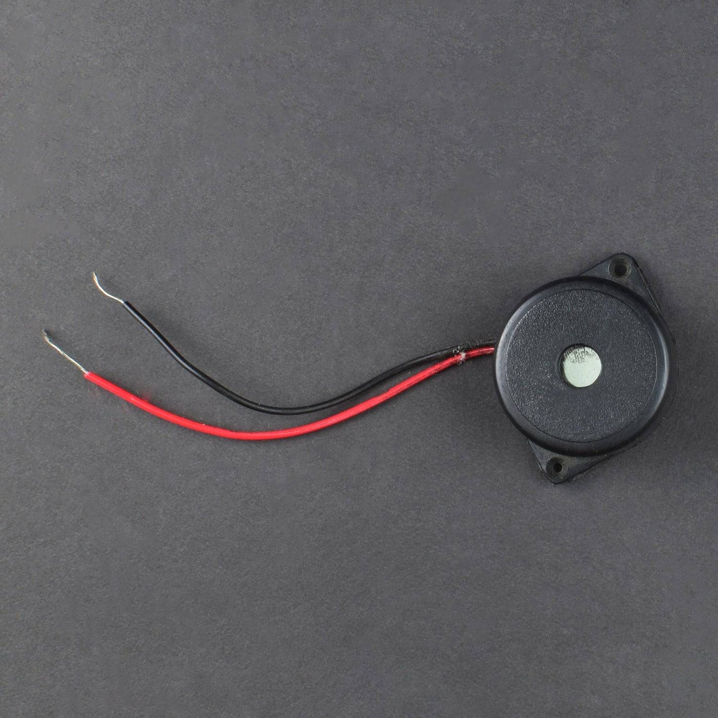
- B-20 Piezo Buzzer – 1
- LED – 2
- Transistor (BC547and BC557) – 2 pieces each
- Single stand wire 2m - 1
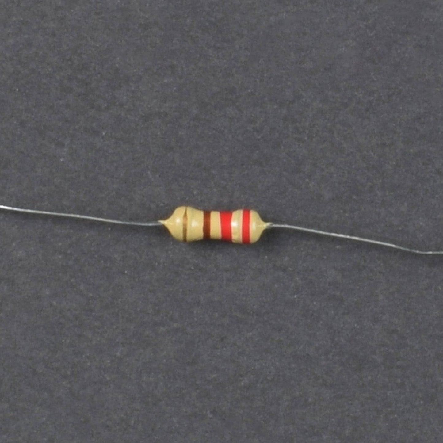
- Resistor (47k – 2 , 33k – 2, 47 ohm – 2 , 68 ohm - 2)
- Capacitor 100 uf – 1
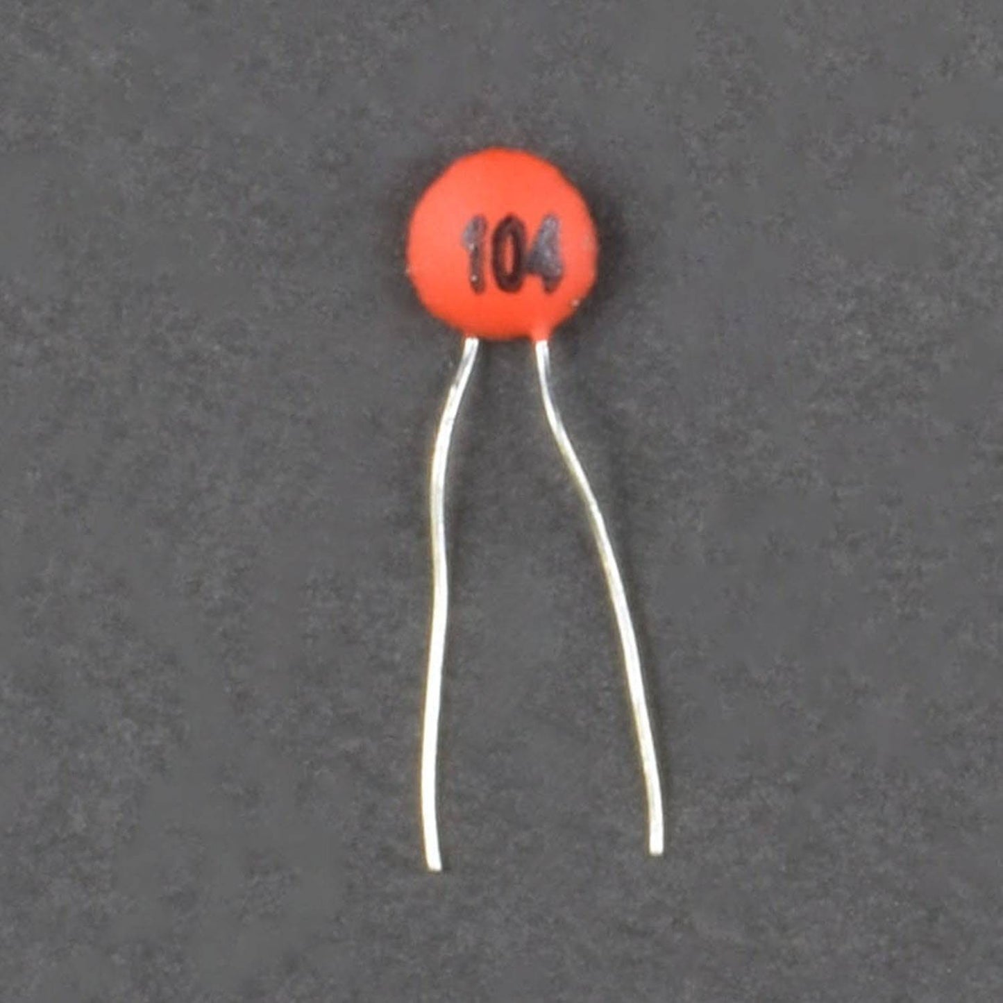
- Ceramic capacitor 0.1 uf - 3
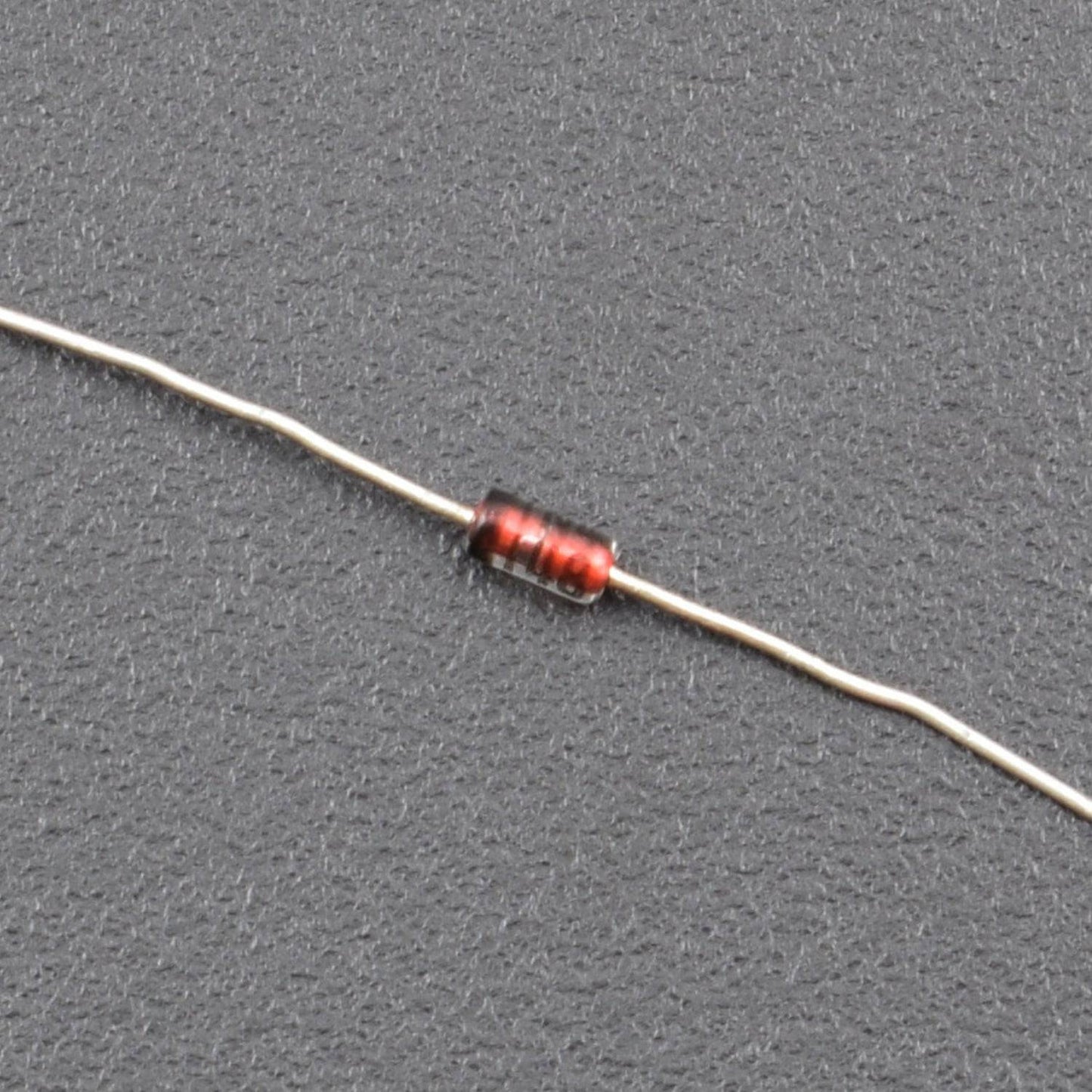
- Diode1N4148 – 2
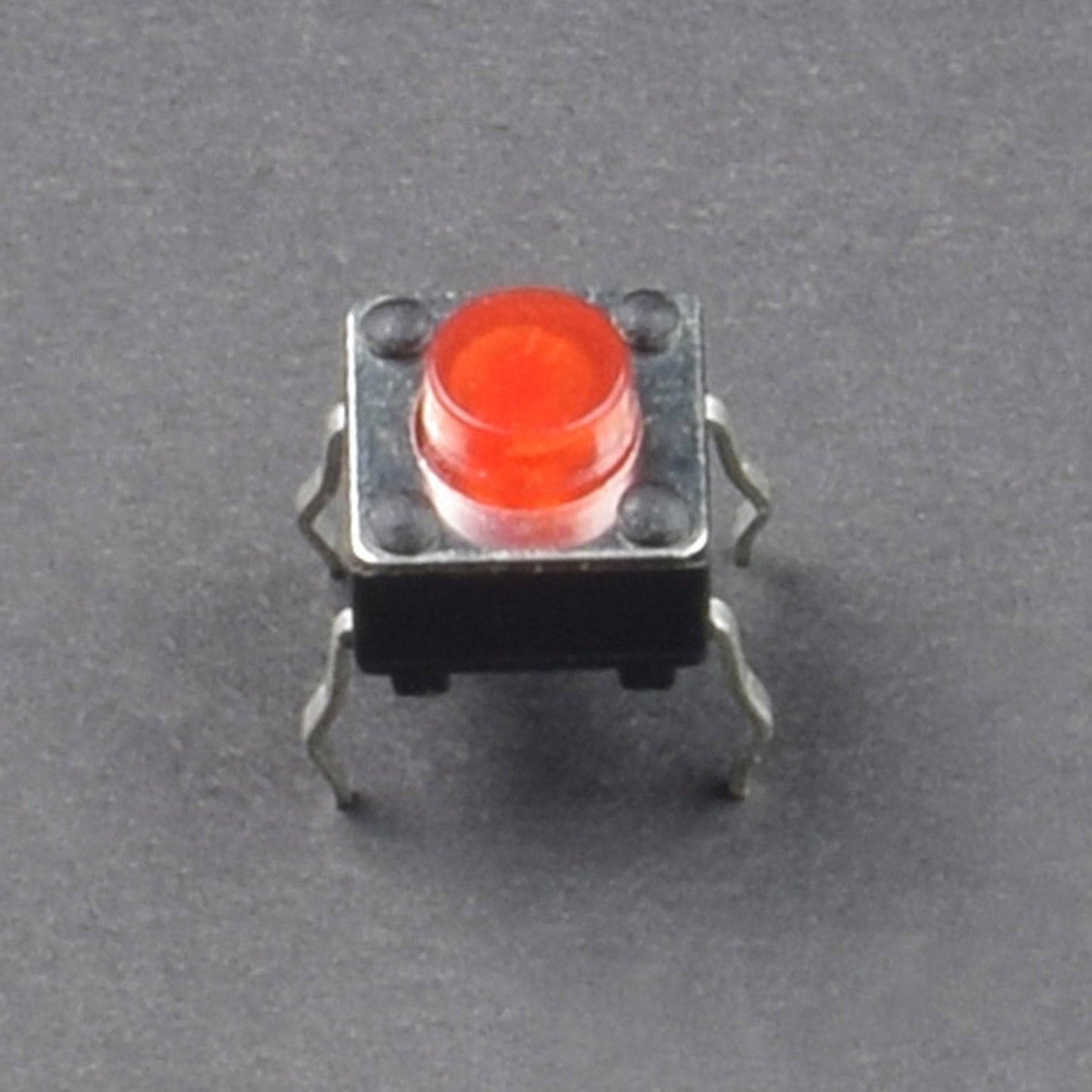
- Push button – 2
HARDWARE REQUIRED
- Breadboard 400 points – 1
- 9v battery -1
- battery snapper – 1
- B-20 Piezo Buzzer – 1
- LED – 2
- Transistor (BC547and BC557) – 2 pieces each
- Single stand wire 2m - 1
- Resistor (47k – 2 , 33k – 2, 47 ohm – 2 , 68 ohm - 2)
- Capacitor 100 uf – 1
- Ceramic capacitor 0.1 uf - 3
- Diode1N4148 – 2
- Push button – 2
SPECIFICATIONS
Power supply – 9V( from 9v battery)
PIN DESCRIPTION
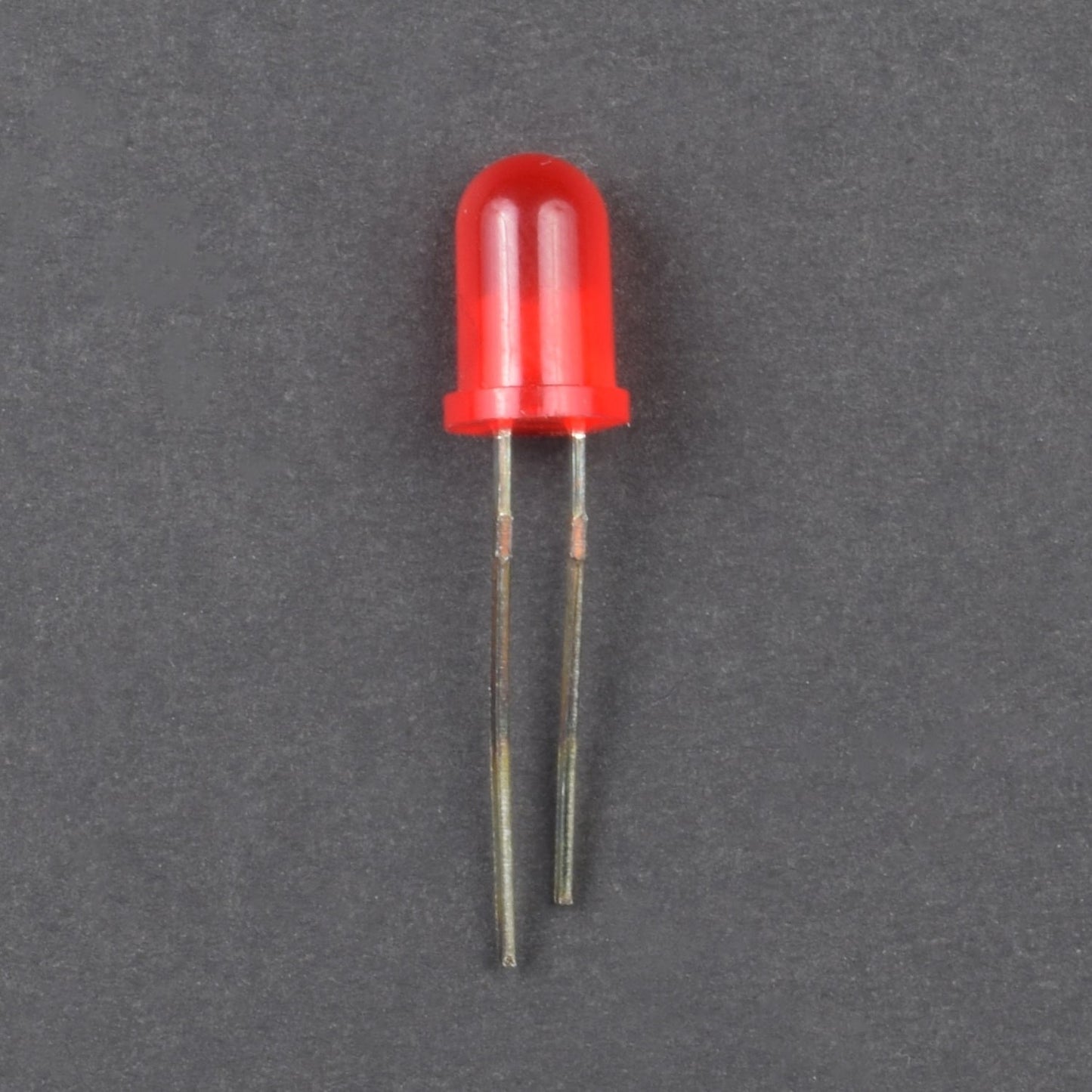
LED


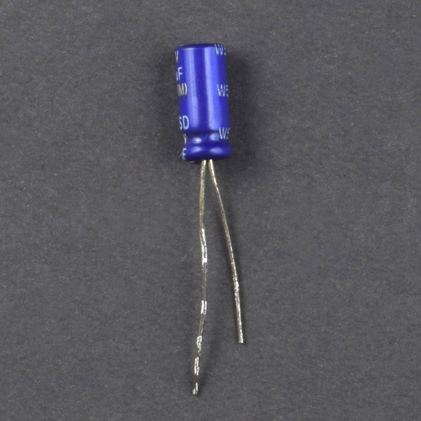
CAPACITOR


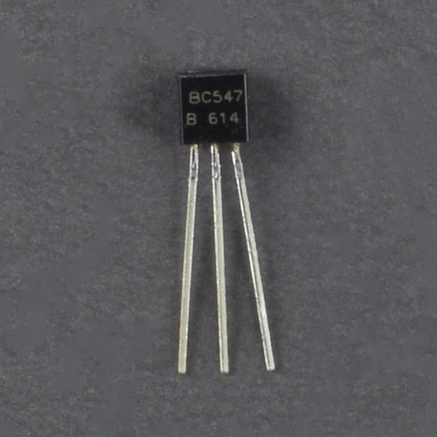
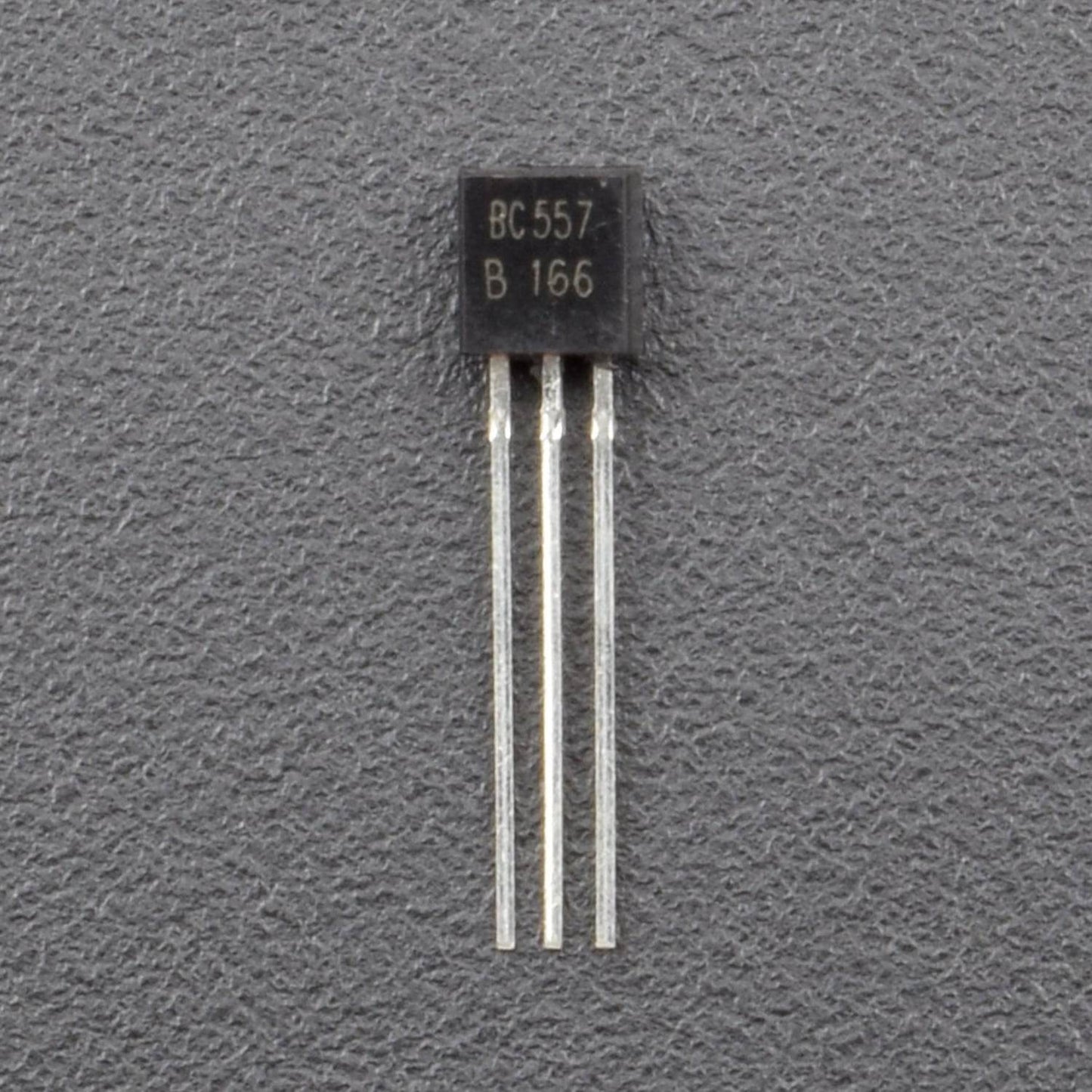
TRANSISTOR
For the Pin Reference


CIRCUIT DESCRIPTION
![]()
![]()
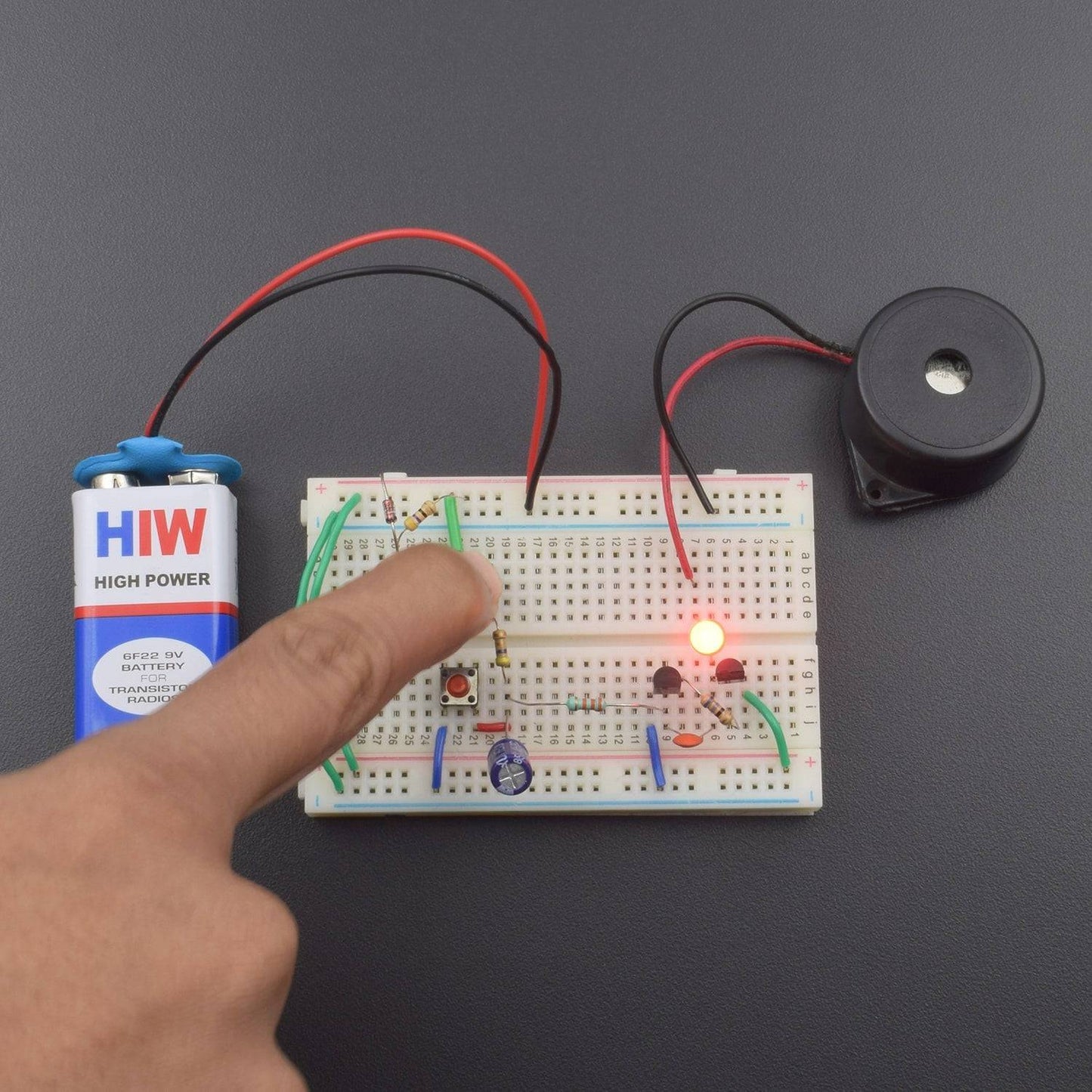
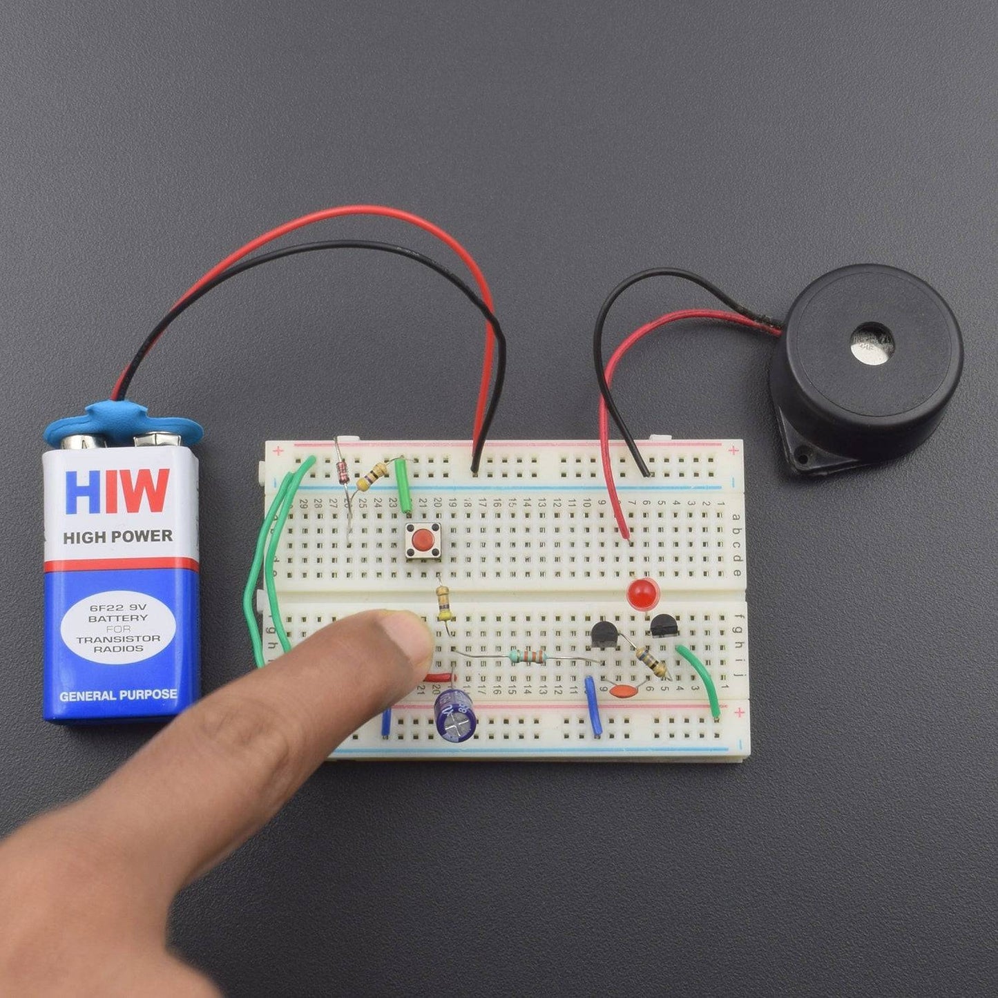
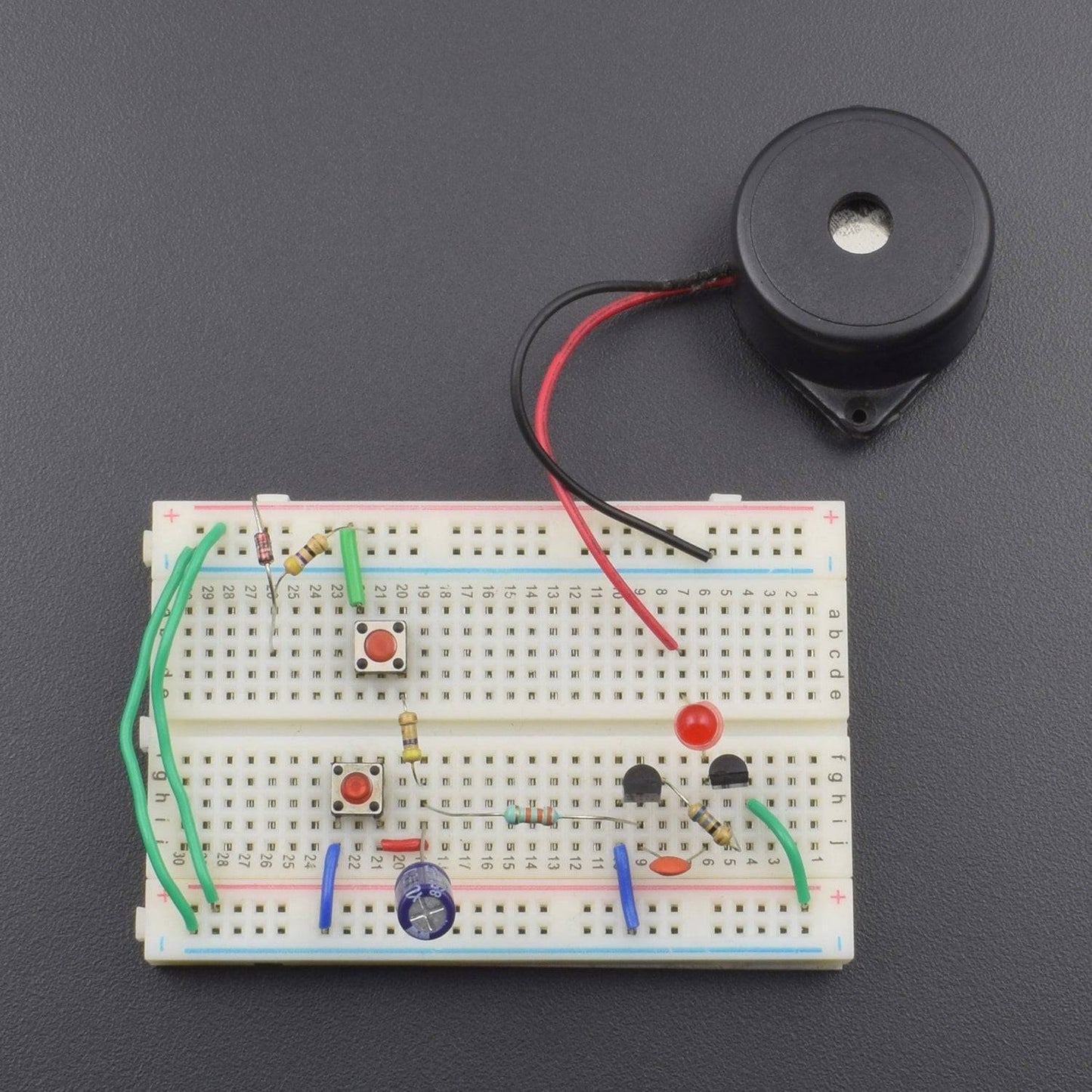
1. Diode positive leg is connected to the positive supply and negative leg connected to the 47ohm resistor and resistor 2nd leg is connected to the positive supply.
2. Push button's connected to the breadboard and push button(1) 1st leg connected to the positive supply and 2nd leg to connected 47K resistor and resistor 2nd leg to connected push button(2) 2nd leg.
3. push button(2) 1st leg is GND.
4. 100uF capacitor positive leg is connected to the push button (2) 2nd leg and capacitor negative leg is GND.
5. transistor's connected to the breadboard.
6. Transistor BC 547 is 1st leg is GND, BC547 2nd leg to connected 33K resistor and resistor 2nd leg connected to the 100uF capacitor positive leg.
7. Transistor BC 547 2nd leg to the connected 0.1uF capacitor (ceramic) and capacitor 2nd leg is connected to the transistor BC 557 1st leg.
8. BC 557 transistor 2nd leg to connected 68-ohm resistor and resistor 2nd leg connected to the BC 547 transistor 3rd leg.
9. BC 557 transistor 3rd leg is connected to the positive supply.
10. BC 557 transistor 1st leg to connected LED positive leg and led negative leg to connected piezo buzzer positive leg and buzzer negative leg is GND.
11. Breadboard connection positive to positive and negative to negative.
WORKING
Electronics siren circuit using 2 transistors when we press the 1st push button then start the buzzer & Led and press 2nd push button buzzer is off.