


vendor-unknown
Make an Automatic Door & counter with HC-SR04 ultrasonic sensor and servo motor interfacing with arduino mega - KT775
Make an Automatic Door & counter with HC-SR04 ultrasonic sensor and servo motor interfacing with arduino mega - KT775
SKU:KT775
1000 in stock
Couldn't load pickup availability
- For Bulk Order Click Here
- Need Customer Support?
- Free Delivery Above 999/-
Note: In case you receive a damaged or faulty product, please return it in the original box with all foam and packaging. Returns will not be accepted if further damage occurs due to improper packing.
If you order a product that is currently in Preorder, and the price of that item increases in the future, you will be required to pay the difference in price.
For refund/return/replacement, call us at +91 95995 94520 or email us at support@rees52.com
Delivery Time
Delivery Time
- Delivery time with the Express Shipping option is 2-3 working days, and with the Standard Shipping option is 5-6 working days. It varies based on location, reliant on courier services.
- Delivery time if the order item is on Preorder Status is 15-20 working days.
COD (Cash on Delivery)
COD (Cash on Delivery)
- For COD you have to pay extra charges of Rs 350/- before the shipment. (We will share the company QR Code, UPI ID or Account details for the same)

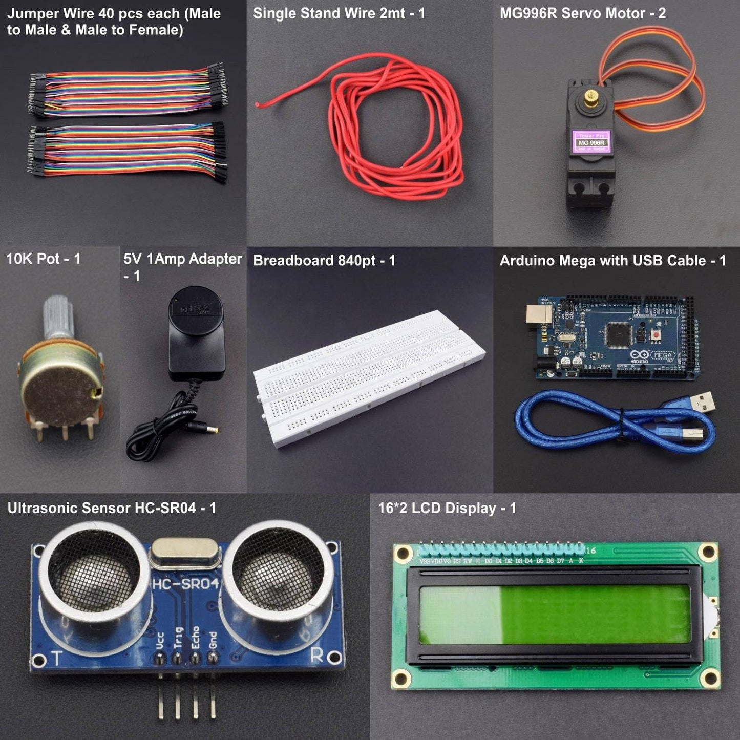
KIT INCLUDES:
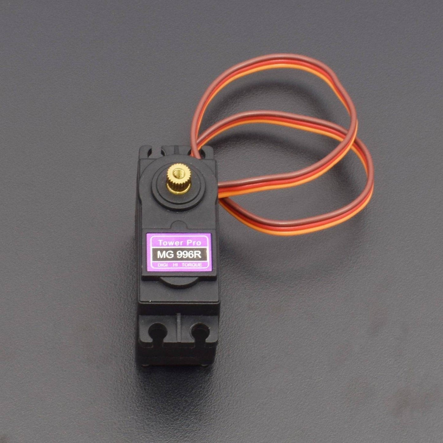
- MG996R servo motor -2
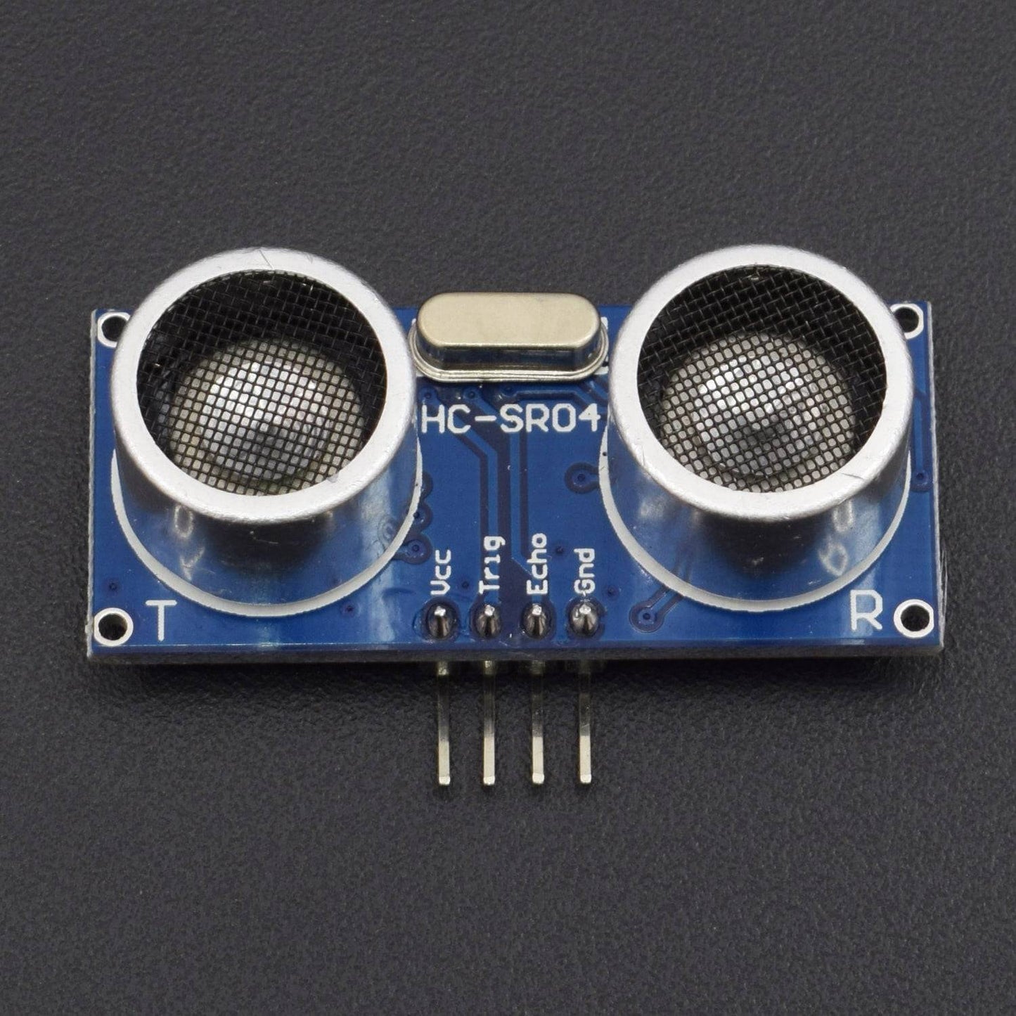
- HC-SR04 ultrasonic sensor -2
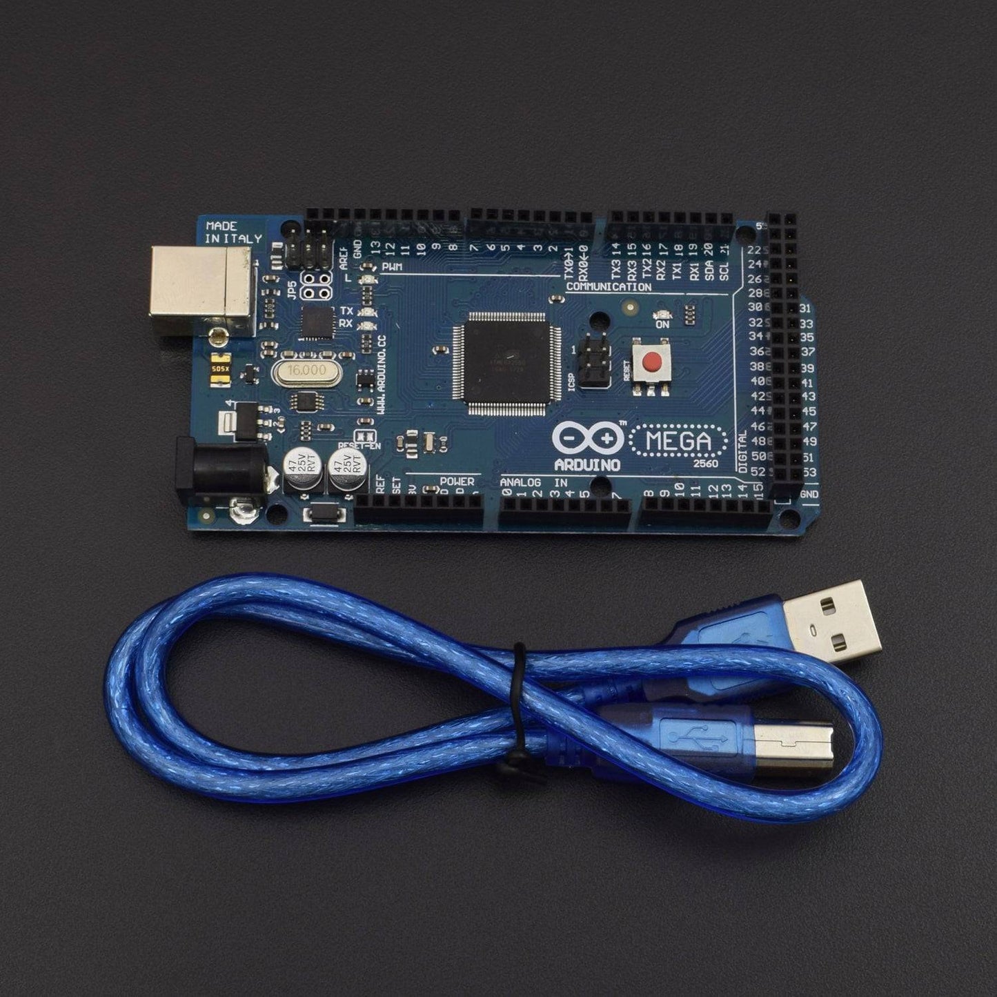
- Arduino mega with cable - 1
- 10k pot - 1
- 16x2 lcd Display - 1
- Breadboard 840 points - 1
- Jumper wires Male to male - 40 pieces
- Jumper wires male to female- 40 pieces
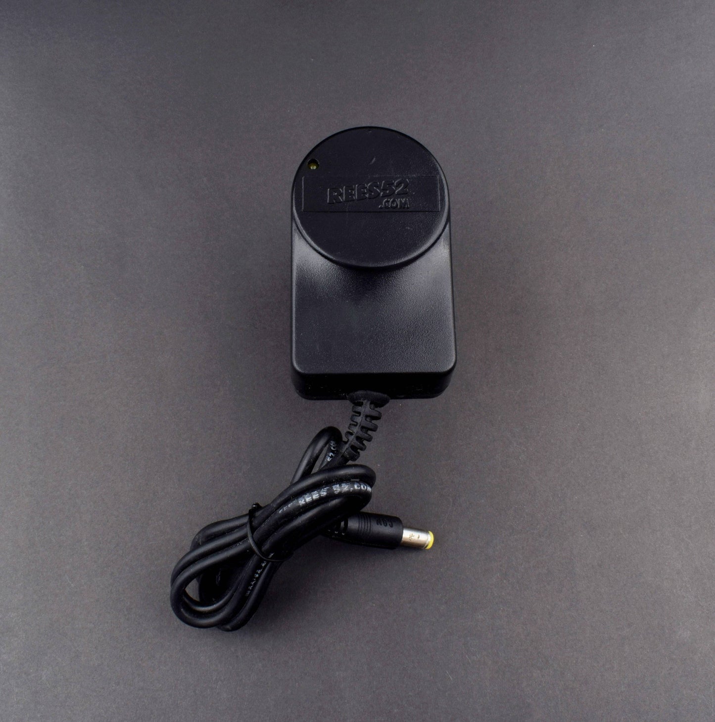
- 5v 1 amp adapter – 1
- Single stand wire 2mt - 1
HARDWARE REQUIRED
- MG996R servo motor -2
- HC-SR04 ultrasonic sensor -2
- Arduino mega with cable - 1
- 10k pot - 1
- 16x2 lcd Display - 1
- Breadboard 840 points - 1
- Jumper wires Male to male - 40 pieces
- Jumper wires male to female- 40 pieces
- 5v 1 amp adapter – 1
- Single stand wire 2mt - 1
SOFTWARE REQUIRED
Arduino IDE 1.8.5 (programmable platform for Arduino)
Click To Download :https://www.arduino.cc/en/Main/Software

SPECIFICATIONS
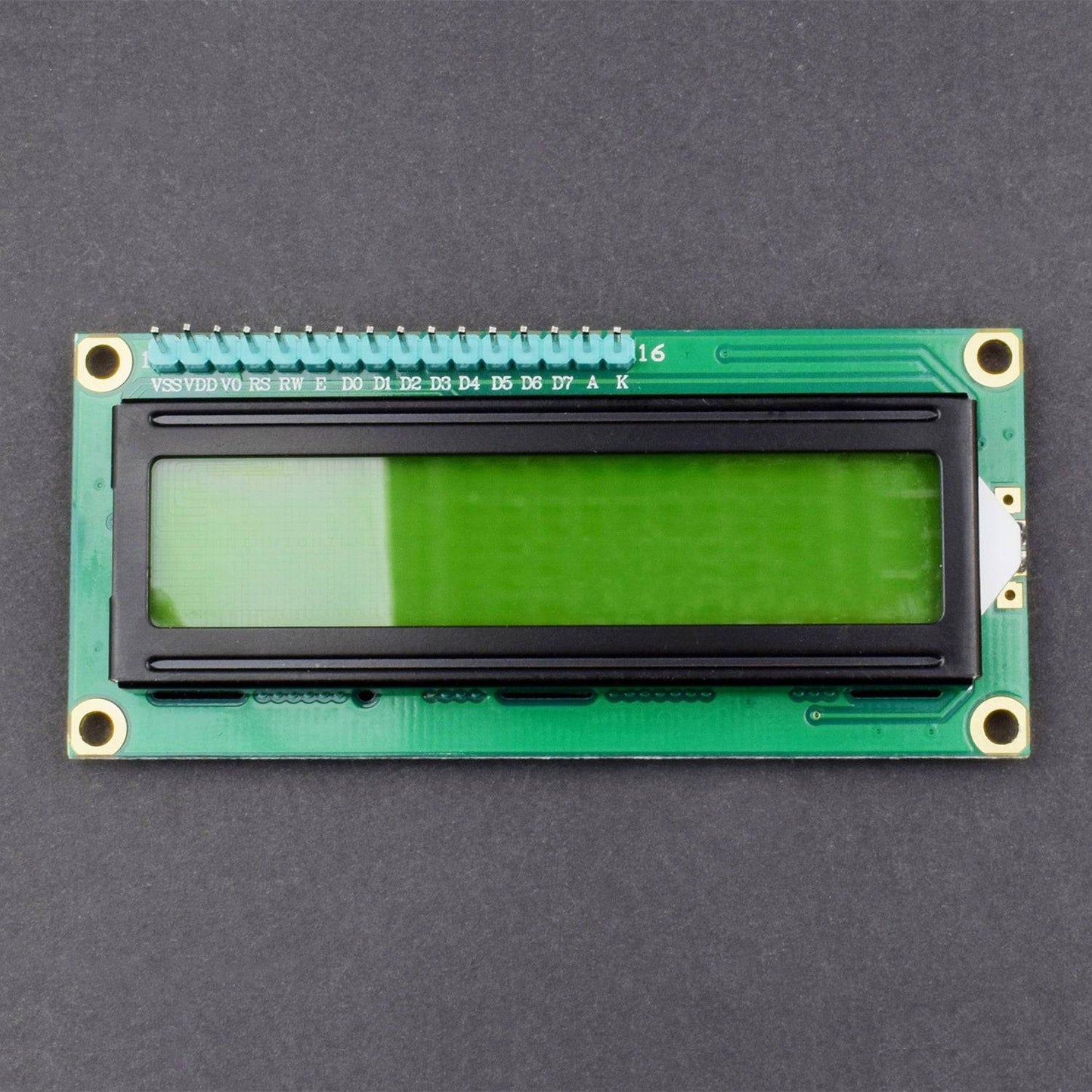
16*2 LCD DISPLAY
- Standard 16x2 Character LCD
- 16 Characters Wide x 2 Lines
- 5 x 8 Dots with Cursor
- Built in Controller (HD44780 or equivalent)
- +3.3V Power Supply
- Backlight Included
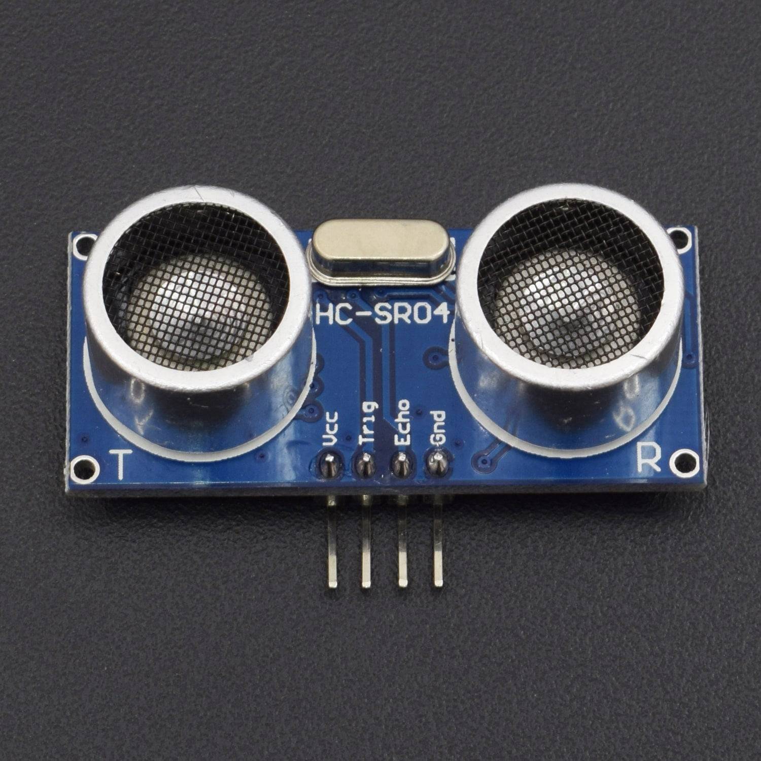
ULTRASONIC SENSOR
- Operating Voltage: 5V
- Static current: 2mA max
- Induction Angle: 15°
- Detection Range: 2 – 200cm
- High precision up to 3mm
PIN DESCRIPTION
16*2 LCD DISPLAY
Symbol |
External Connection |
Function |
VSS |
Power Supply |
Signal GROUND for lcm |
VDD |
POWER SUPPLY for logic lcm |
|
V0 |
Contrast Adjust |
|
RS |
MPU |
Register Select Signal |
RW |
MPU |
Read/Write Select Signal |
E |
MPU |
Operation Enable Signal |
DB0~DB3 |
MPU |
Four Low order bidirectional three state bus lines. Used for data transfer between the MPU and LCM. These four are not used between 4 Bit operations. |
DB4~DB7 |
MPU |
Four high order bidirectional Three state bus lines used for data transfer between the MPU |
A |
LED BKL power Supply |
Power Supply for BKL |
K |
NOTE |
|
|

ULTRASONIC SENSOR

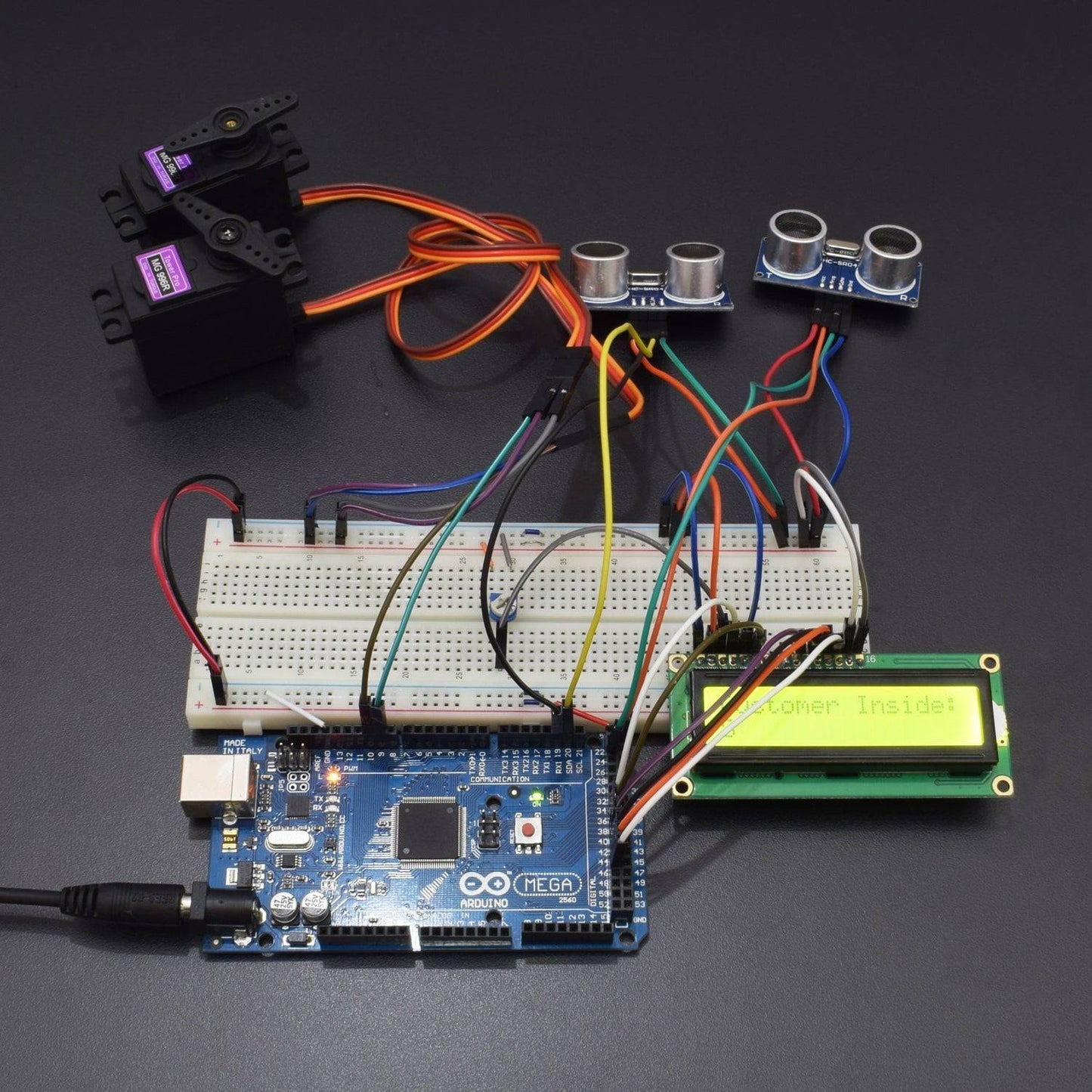
CIRCUIT CONNECTION
- Connect Servo motor’s negative to negative rail and positive to the positive rail
- Connect Servo 1 signal is connected to Digital pin D7 of mega and of servo 2 to Digital pinD10 of mega.
- Ultrasonic sensor's ground to negative rail and Vcc to the positive rail
- Connect Ultrasonic sensor 1 trigger and echo to Arduino pin D19 and D20 and ultrasonic sensor 2 trigger and echo to D23 and D24 of mega
- Connect 10k pot negative and positive to negative and positive rail on breadboard and data pin to pin 3 of LCD.
- Connect Arduino ground to negative rail and 5v to the positive rail
- Connect LCD pin 1 to GND, pin 2 to 5v, pin 4 to D36 of, pin 5 to GND, pin 6 to D38, pin11 to D40, pin12 to D42, pin 13 to D44, pin 14 to D46 of mega, pin 15 to 5v and pin 16 to end.
- Connect breadboard positive to positive and negative to the negative rail

CODE
WORKING
The project is composed of different common components like the servo motor, ultrasonic sensor, and an output LCD Display. The complete project works in the way that all movements detected on the left door, counts the counter up, making it say that a specific number of person is inside the establishment, on the other hand, counting down signifies that this sum of persons has left the establishment.