


vendor-unknown
Make a Wireless Transmitter and Receiver using RF Modules - KT817
Make a Wireless Transmitter and Receiver using RF Modules - KT817
SKU:KT817
1000 in stock
Couldn't load pickup availability
- For Bulk Order Click Here
- Need Customer Support?
- Free Delivery Above 999/-
Note: In case you receive a damaged or faulty product, please return it in the original box with all foam and packaging. Returns will not be accepted if further damage occurs due to improper packing.
If you order a product that is currently in Preorder, and the price of that item increases in the future, you will be required to pay the difference in price.
For refund/return/replacement, call us at +91 95995 94520 or email us at support@rees52.com
Delivery Time
Delivery Time
- Delivery time with the Express Shipping option is 2-3 working days, and with the Standard Shipping option is 5-6 working days. It varies based on location, reliant on courier services.
- Delivery time if the order item is on Preorder Status is 15-20 working days.
COD (Cash on Delivery)
COD (Cash on Delivery)
- For COD you have to pay extra charges of Rs 350/- before the shipment. (We will share the company QR Code, UPI ID or Account details for the same)

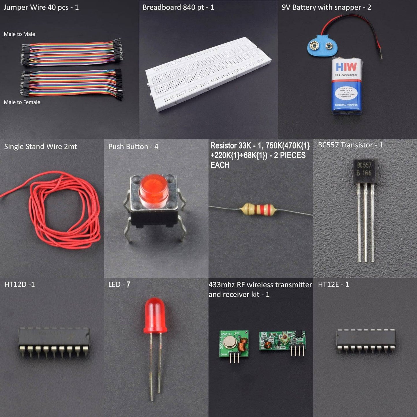


KIT INCLUDES:
- HT12E - 1
- HT12D -1
- RF Receiver & Transmitter - 1
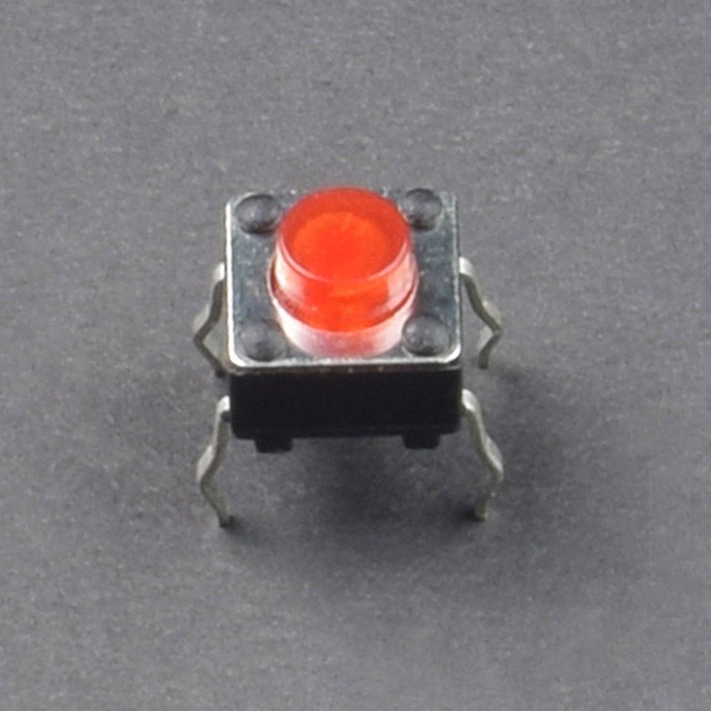
- Push Button - 4
- LED - 5
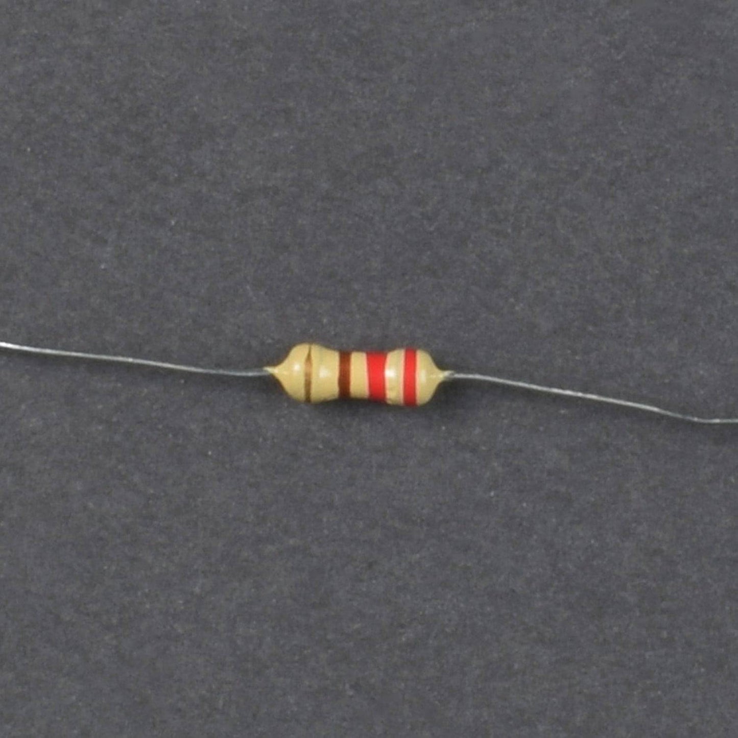
- Resistor 33K - 1, 750K(470K{1}+220K{1}+68K{1}) - 1
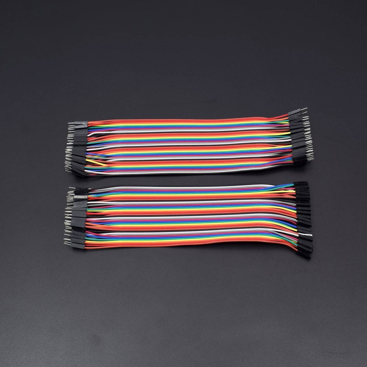
- Jumper wire male to female – 40 pieces
- Jumper wire male to male – 40 pieces
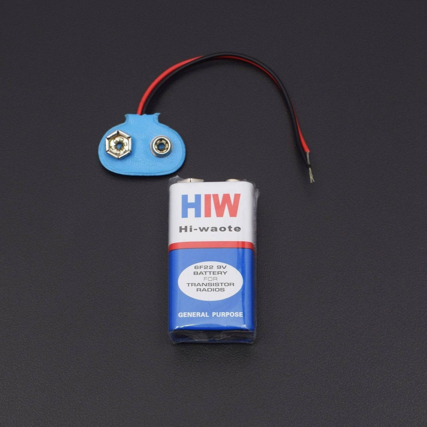
- 9V Battery - 2
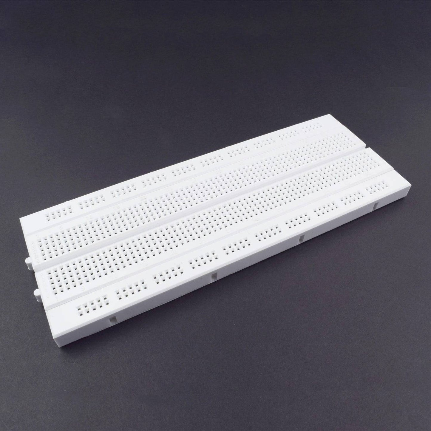
- Breadboard 840 POINTS – 1
HARDWARE REQUIRED
- HT12E - 1
- HT12D -1
- RF Receiver & Transmitter - 1
- Push Button - 4
- LED - 5
- Resistor 33K - 1, 750K(470K{1}+220K{1}+68K{1}) - 1
- Jumper wire male to female – 40 pieces
- Jumper wire male to male – 40 pieces
- 9V Battery - 2
- Breadboard 840 POINTS – 1
SPECIFICATIONS
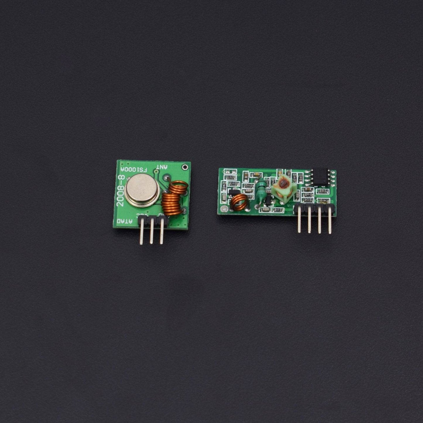
433mhz RF wireless transmitter and receiver kit
- Frequency: 433Mhz.
- Modulation: ASK
- Receiver Data Output: High - 1/2 Vcc, Low - 0.7v
- Transmitter Input Voltage: 3-12V (high voltage = more transmitting power)
- Receiver Input Voltage : 3.3-6V (high voltage = more receiving power)
PIN DESCRIPTION
433mhz RF wireless transmitter and receiver kit


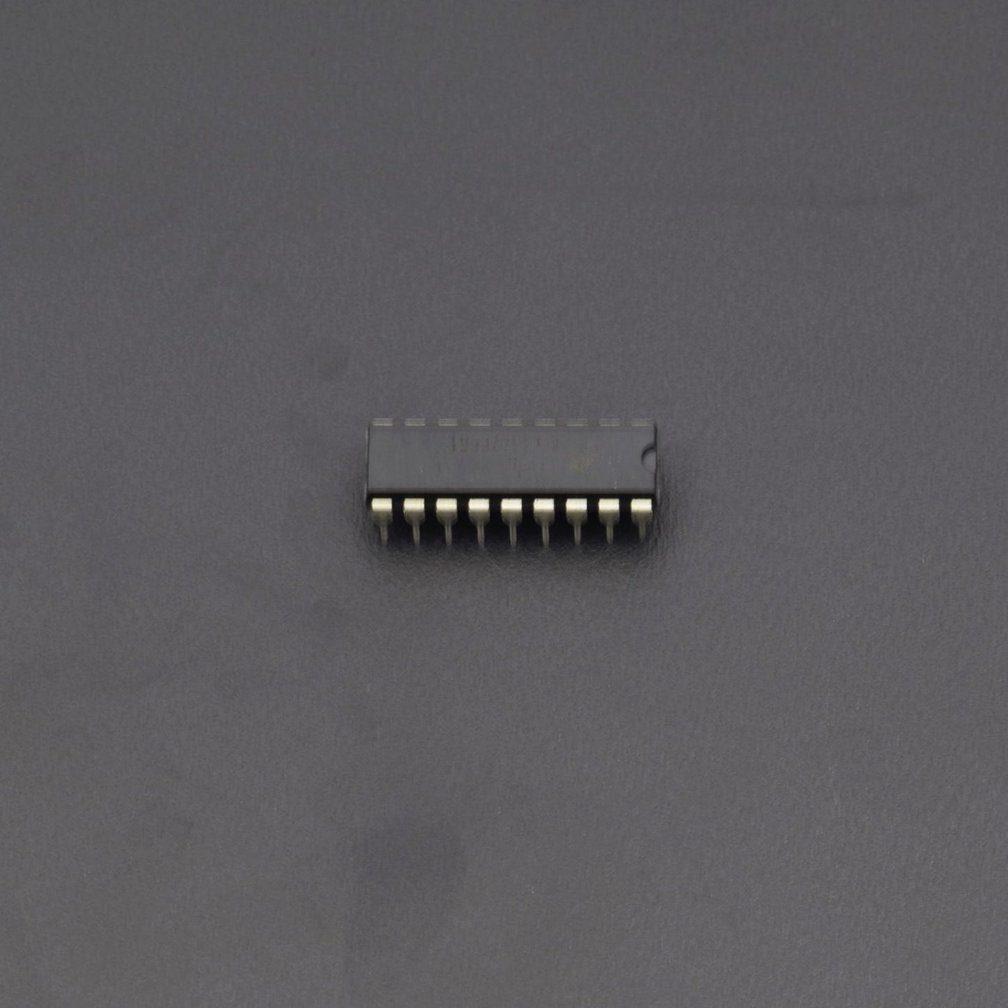
HT12E Encoder IC
HT12E is an encoder integrated circuit of 212 series of encoders. HT12E converts the parallel inputs into serial output.


HT12D IC
HT12D is a decoder integrated circuit that belongs to 212 series of decoders. HT12D converts the serial input into parallel outputs. It decodes the serial addresses and data received by, say, an RF receiver, into parallel data and sends them to output data pins.


CIRCUIT DESCRIPTION
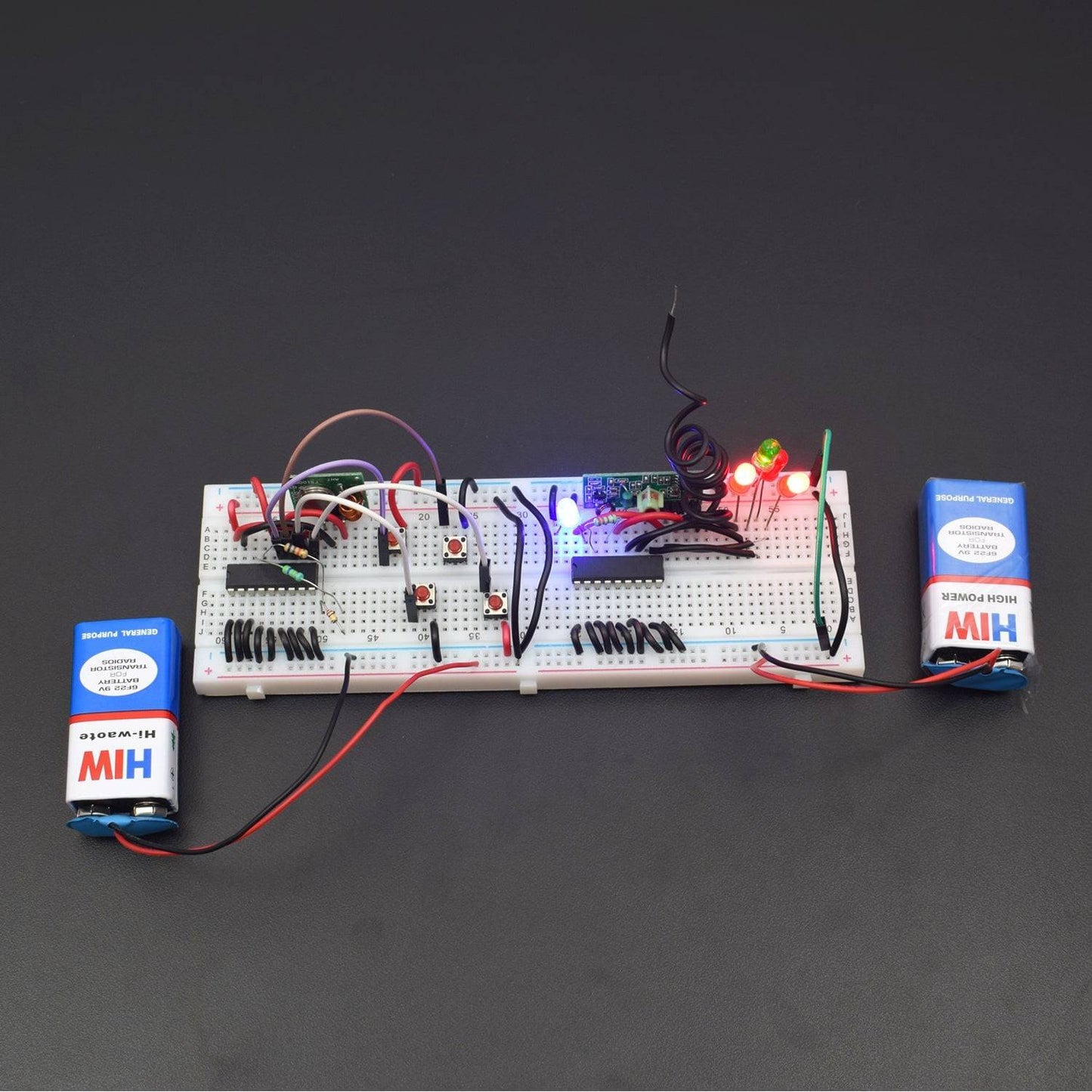
(A) Transmitter connection:-
- HT12E IC and RF Transmitter connected to the Breadboard.
- HT12E IC Pin 1,2,3,4,5,6,7,8, 9 & 14 are GND and Pin 18 connected to the positive supply.
- RF Transmitter pin vss connected to the positive supply, GND pin connected to the GND and DATA pin connected to the Pin 17 of HT12E IC.
- Pin 15 of HT12E IC to connected 750K(470K+220K+68K{in series connection}) Resistor and Resistor 2nd leg connected to the Pin 16 of HT12E IC.
- HT12E IC Pin 8,9,10 & 11 connected to the each Push Button 1st led and each Push Button 2nd leg is GND.
- Breadboard connection positive to positive and negative to negative.
![]()
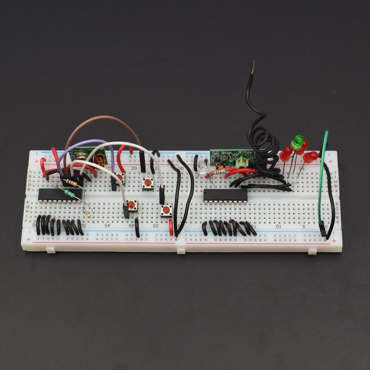
(B) Receiver connection:-
- HT12D IC and RF Receiver connected to the breadboard.
- HT12D IC Pin 1,2,3,4,5,6,7,8 & 9 are GND and Pin 18 connected to the positive supply.
- RF Receiver Pin vss connected to the positive supply and GND pin connected to the GND and DATA Pin connected to the Pin 14 of HT12D IC and antenna pin to connected wire antenna.
- HT12D IC Pin 17 to connected led positive leg and led negative leg is GND.
- Pin 15 of HT12D IC to connected 33K Resistor and Resistor 2nd leg connected to the Pin 16 of HT12D IC.
- Pin 10,11,12 & 13 of HT12D IC to connected LED positive leg and negative leg is GND.
- Breadboard connection positive to positive and negative to negative.

WORKING
Communication over Radio Frequency has many advantages as it doesn’t require a line of sight connection between the transmitter and receiver as in case of Infrared communication.
The range of RF communication is very high when compared to IR communication. In this project, a wireless transmitter and receiver system using RF modules (RF Transmitter and RF Receiver) is implemented.
An RF Transmitter and Receiver pair is used for wireless communication. The wireless data transmission is done using 433 MHz Radio Frequency signals that are modulated using Amplitude Shift Keying (ASK) Modulation technique.
In order to implement the wireless transmitter and receiver, we use an encoder IC HT12E and a decoder IC HT12D.
HT12E:-
It is an encoder IC that converts the 4-bit parallel data from the 4 data pins into serial data in order to transmit over RF link using transmitter.
HT12D:-
It is a decoder IC that converts the serial data received by the RF Receiver into 4-bit parallel data and drives the LEDs accordingly.
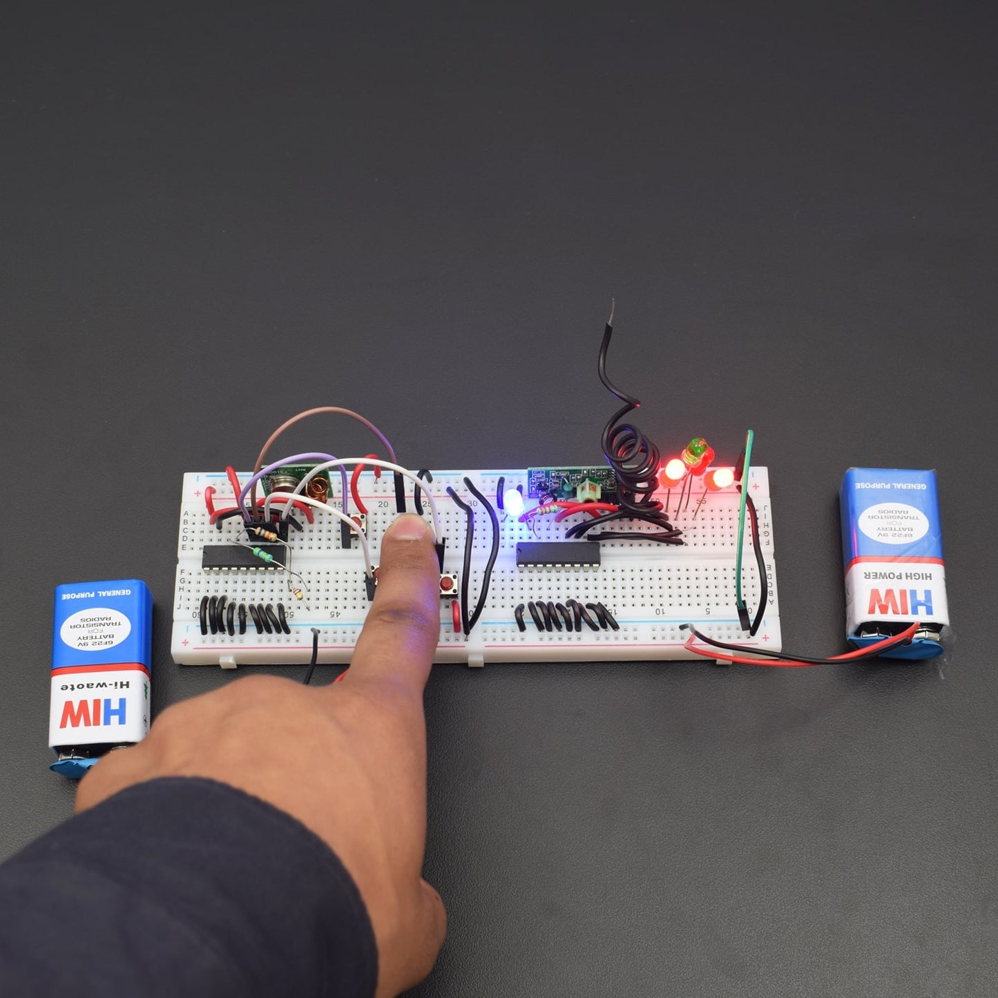
The aim of this project is to implement a wireless transmitter and receiver using RF modules. It uses radio signals to transmit the data. The working of the project is as follows.
The transmitter and receiver sections are placed at a distance of at least 20 meters. In order to show the working of wireless communication between transmitter and receiver, 4 LEDs at receiver side are controlled by 4 buttons at transmitter section.
The HT12E encoder IC converts the 4-bit data from the 4 data pins that are connected to buttons into serial data. This serial data is sent to RF transmitter. The RF transmitter transmits this serial data using radio signals.
At the receiver side, the RF receiver receives the serial data. This serial data is sent to HT12D decoder IC which converts into 4 bit parallel data.
The 4 data pins of decoder are connected to LEDs. According to the buttons pushed, the LEDs can be turned ON or OFF.