


vendor-unknown
Make a wireless LPG gas detection alarm using MQ-6 gas sensor interfacing with Arduino Leonardo - KT787
Make a wireless LPG gas detection alarm using MQ-6 gas sensor interfacing with Arduino Leonardo - KT787
SKU:KT787
997 in stock
Couldn't load pickup availability
- For Bulk Order Click Here
- Need Customer Support?
- Free Delivery Above 999/-
Note: In case you receive a damaged or faulty product, please return it in the original box with all foam and packaging. Returns will not be accepted if further damage occurs due to improper packing.
If you order a product that is currently in Preorder, and the price of that item increases in the future, you will be required to pay the difference in price.
For refund/return/replacement, call us at +91 95995 94520 or email us at support@rees52.com
Delivery Time
Delivery Time
- Delivery time with the Express Shipping option is 2-3 working days, and with the Standard Shipping option is 5-6 working days. It varies based on location, reliant on courier services.
- Delivery time if the order item is on Preorder Status is 15-20 working days.
COD (Cash on Delivery)
COD (Cash on Delivery)
- For COD you have to pay extra charges of Rs 350/- before the shipment. (We will share the company QR Code, UPI ID or Account details for the same)


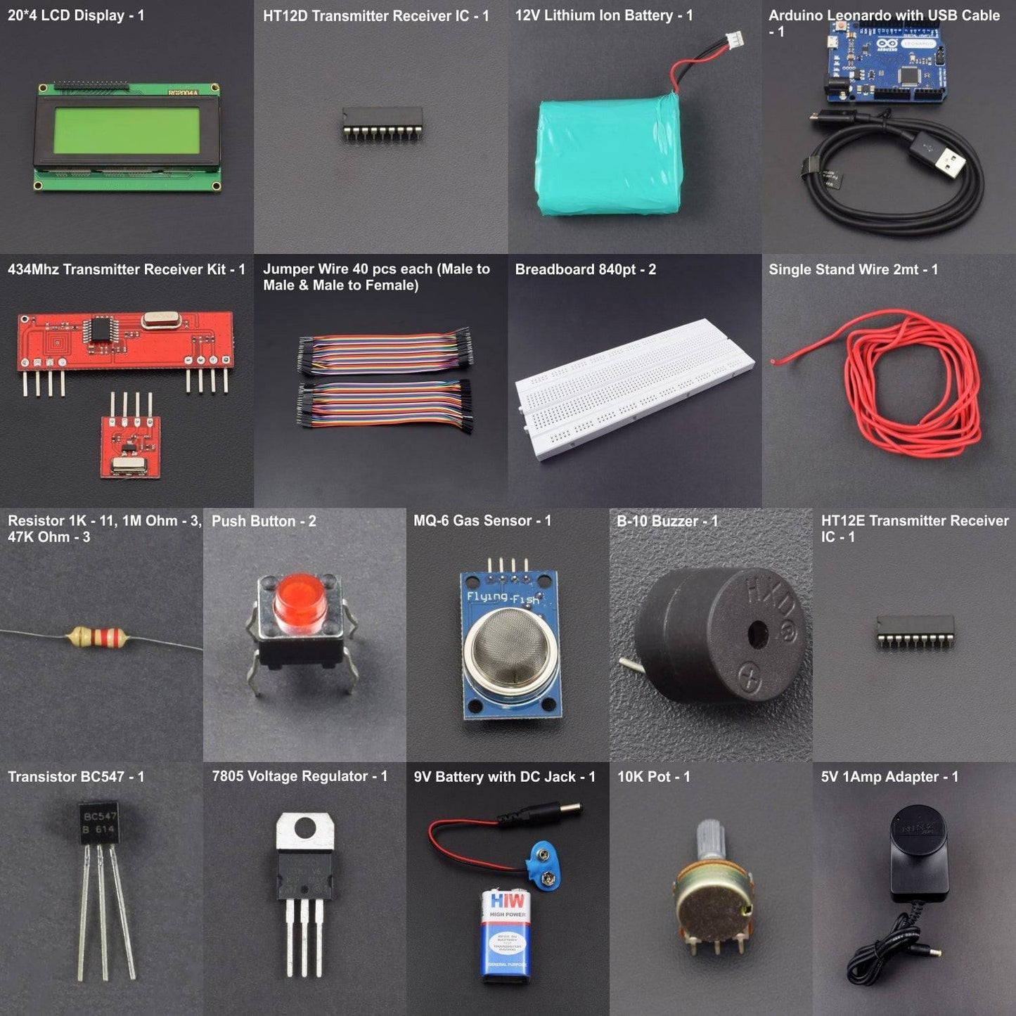
kit included:

Gas leakage is one of the common reasons for fire breakouts. A leakage turns out to be cause of terrible accident particularly in closed buildings. This is a gas leakage detection project based on Arduino UNO. The low cost project uses MQ6 gas sensor which can be calibrated to detect leakage levels based on surroundings. The installation generates a sound alert using buzzer on detection of a dangerous leakage. The project utilizes the 434 MHz RF module so the alarm can be installed anywhere within the building and even multiple alarms can be installed within a building.
HARDWARE REQUIRED
- 20*4 LCD Display – 1
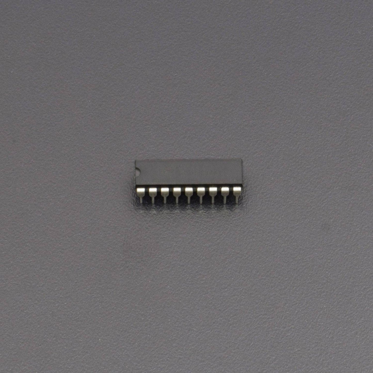
- HT12D Transmitter Receiver IC – 1
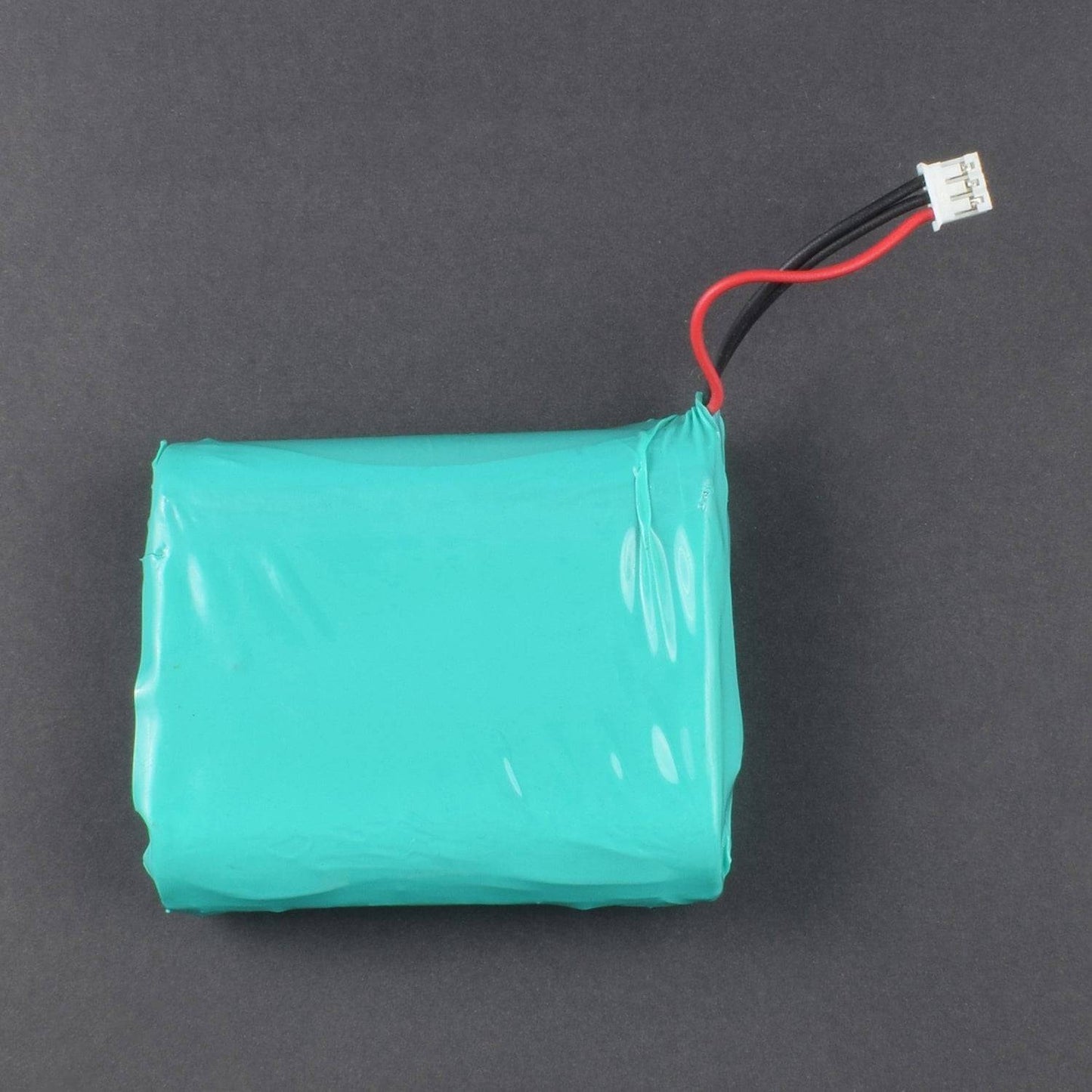
- 12v Lithium-ion battery – 1
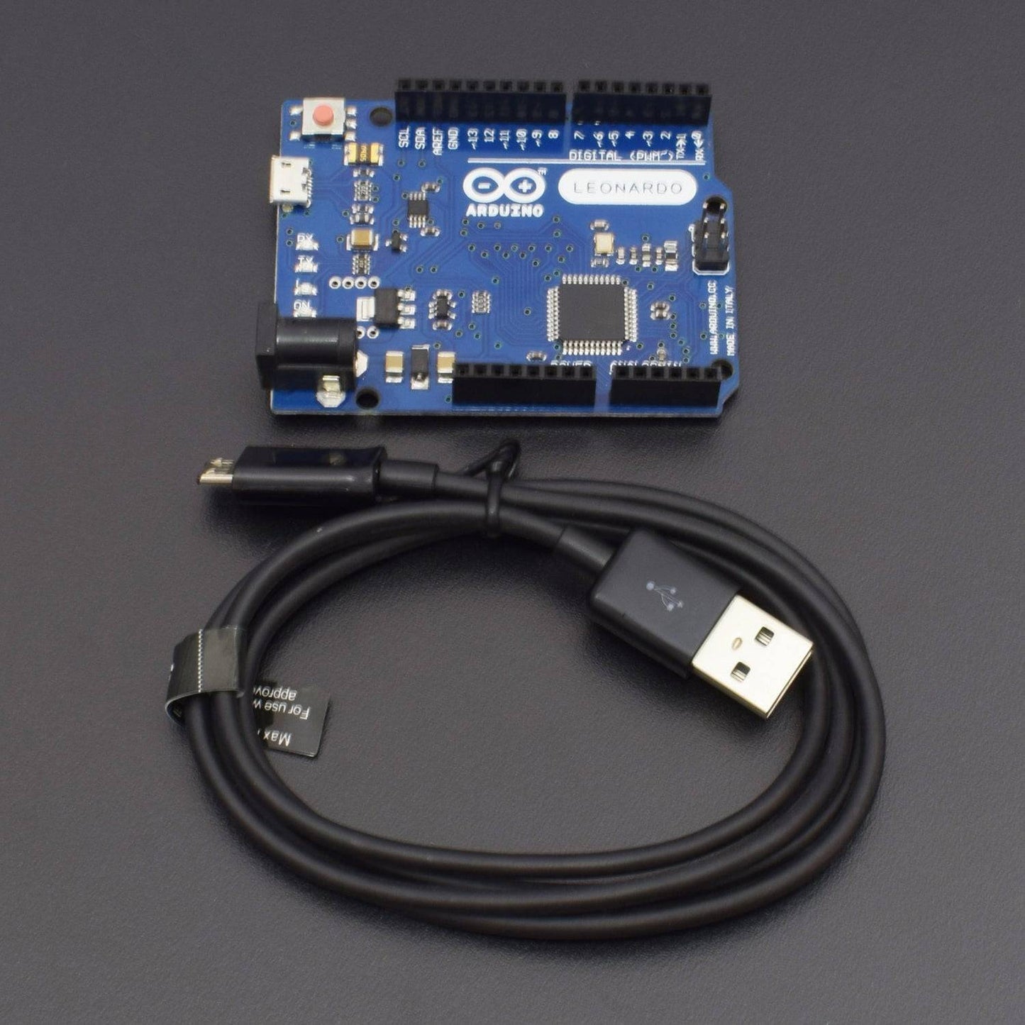
- Arduino Leonardo with USB cable – 1
- 434Mhz Transmitter Receiver kit – 1
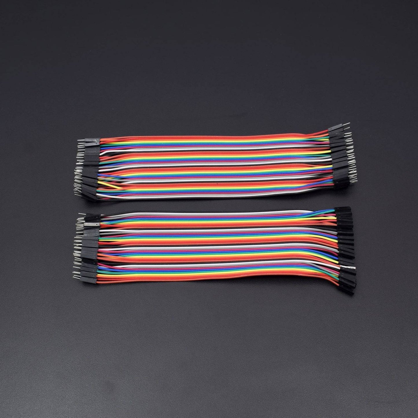
- Jumper wire 40 pcs each male to male
- Jumper wire 40 pcs each male to female
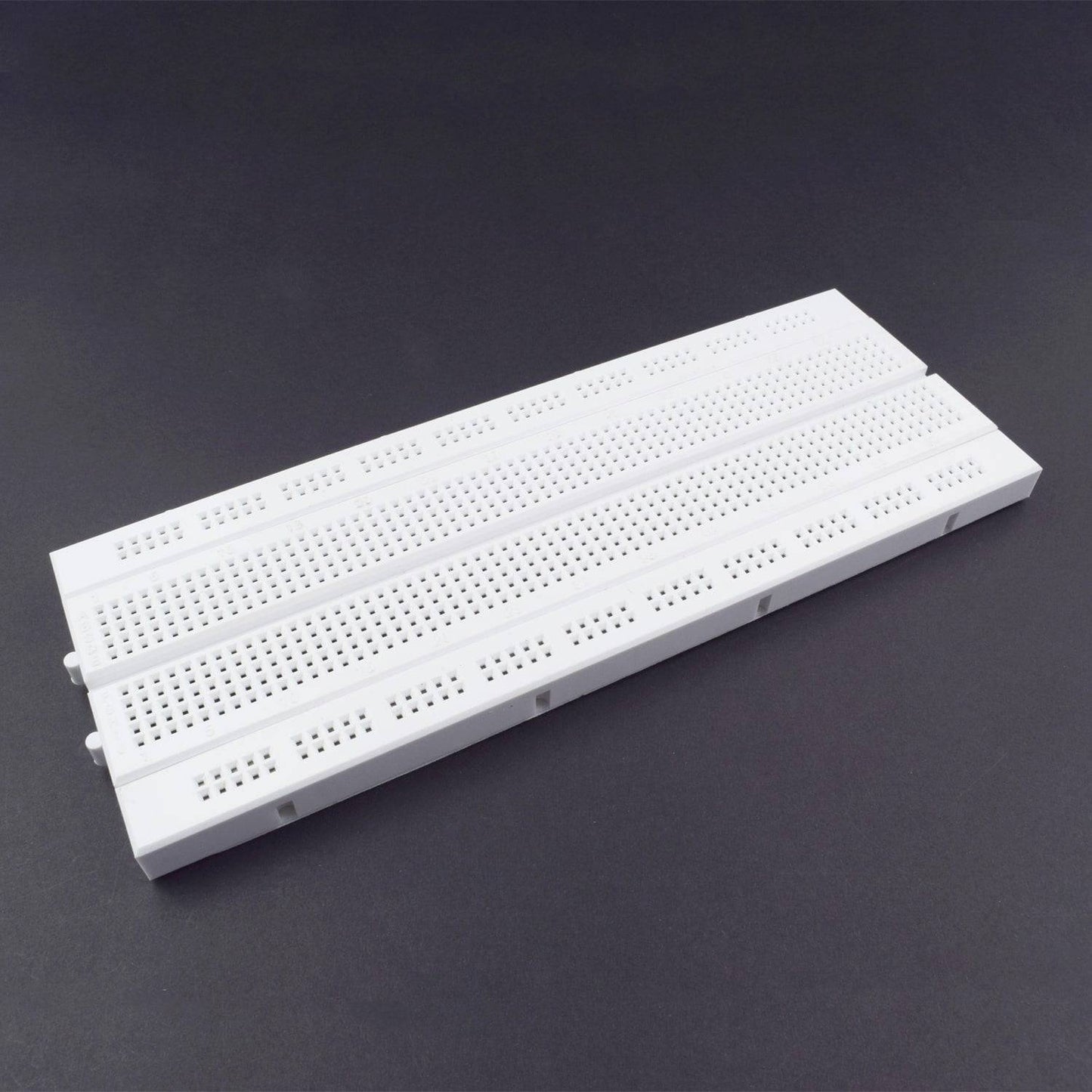
- Breadboard 840 pt. – 2
- Single stand wire 2mt – 1
- Resistor 1k-11 , 1m ohm – 3 , 47kohm – 3
- Push button – 2
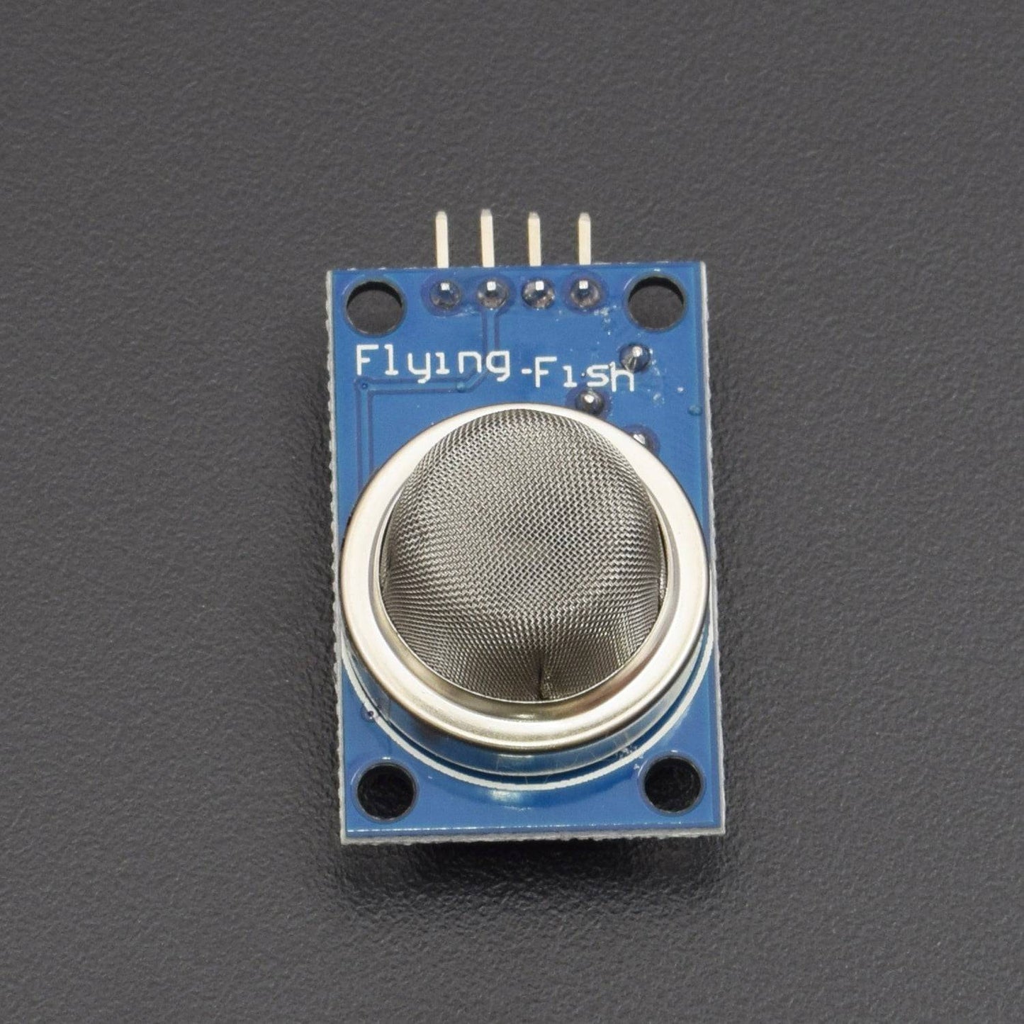
- MQ-6 Gas Sensor – 1
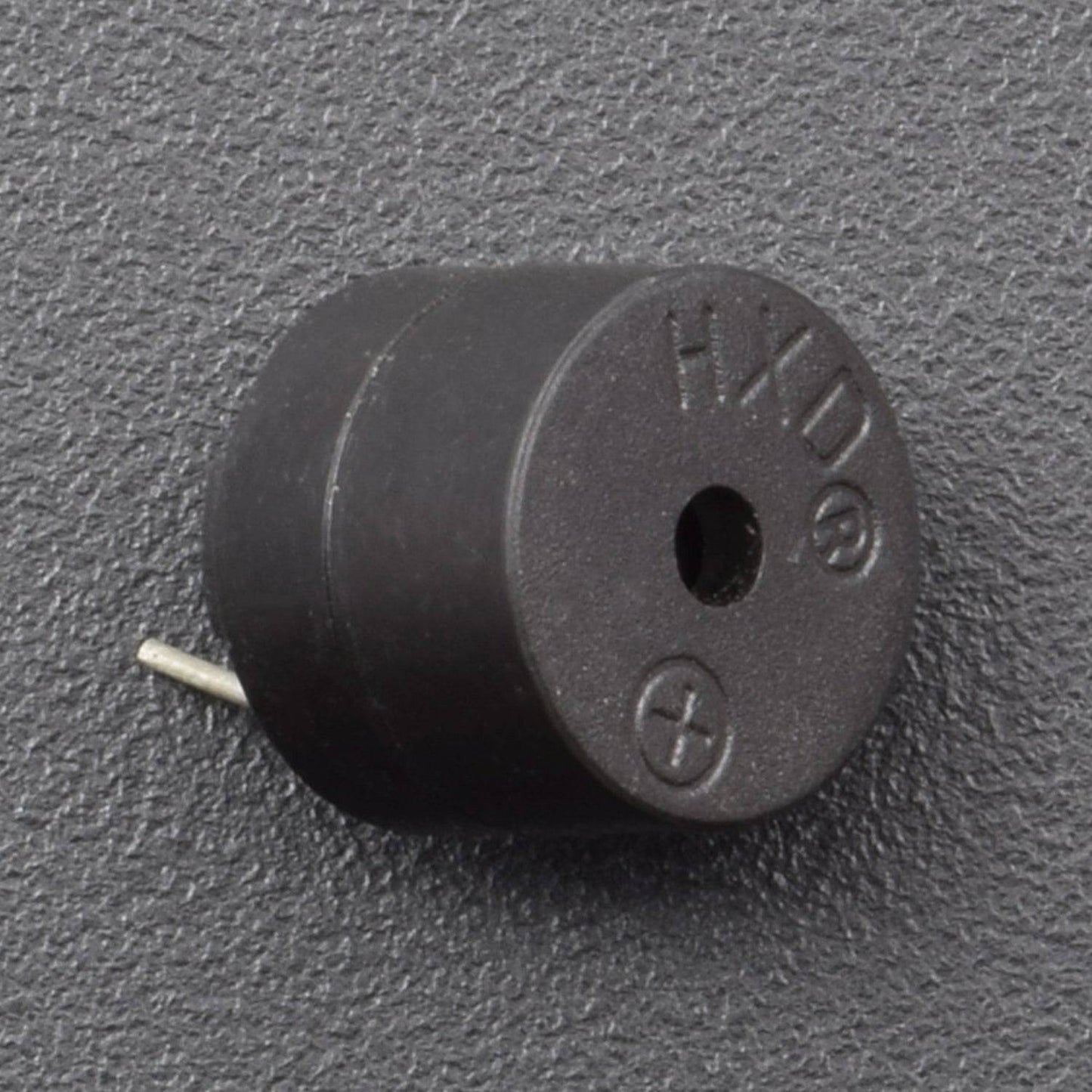
- B10 buzzer – 1
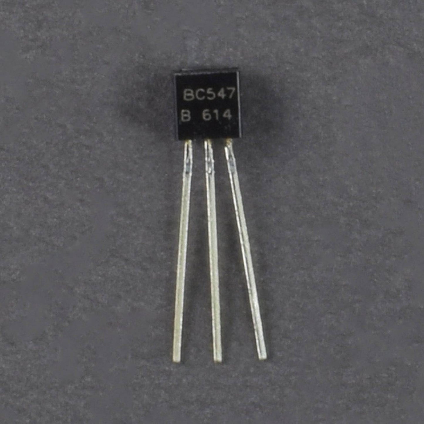
- Transistor BC547 – 1
- 7805 Voltage Regulator – 1
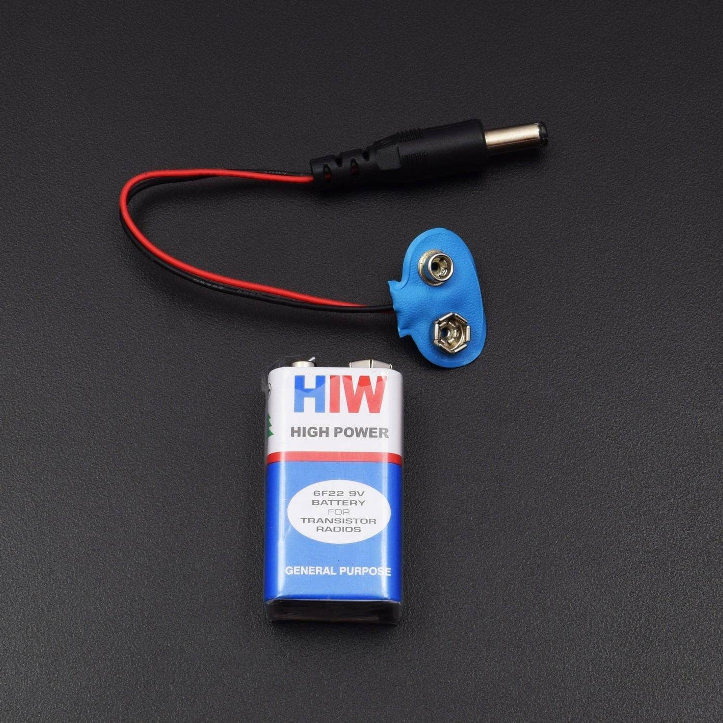
- 9v battery with DC jack – 1
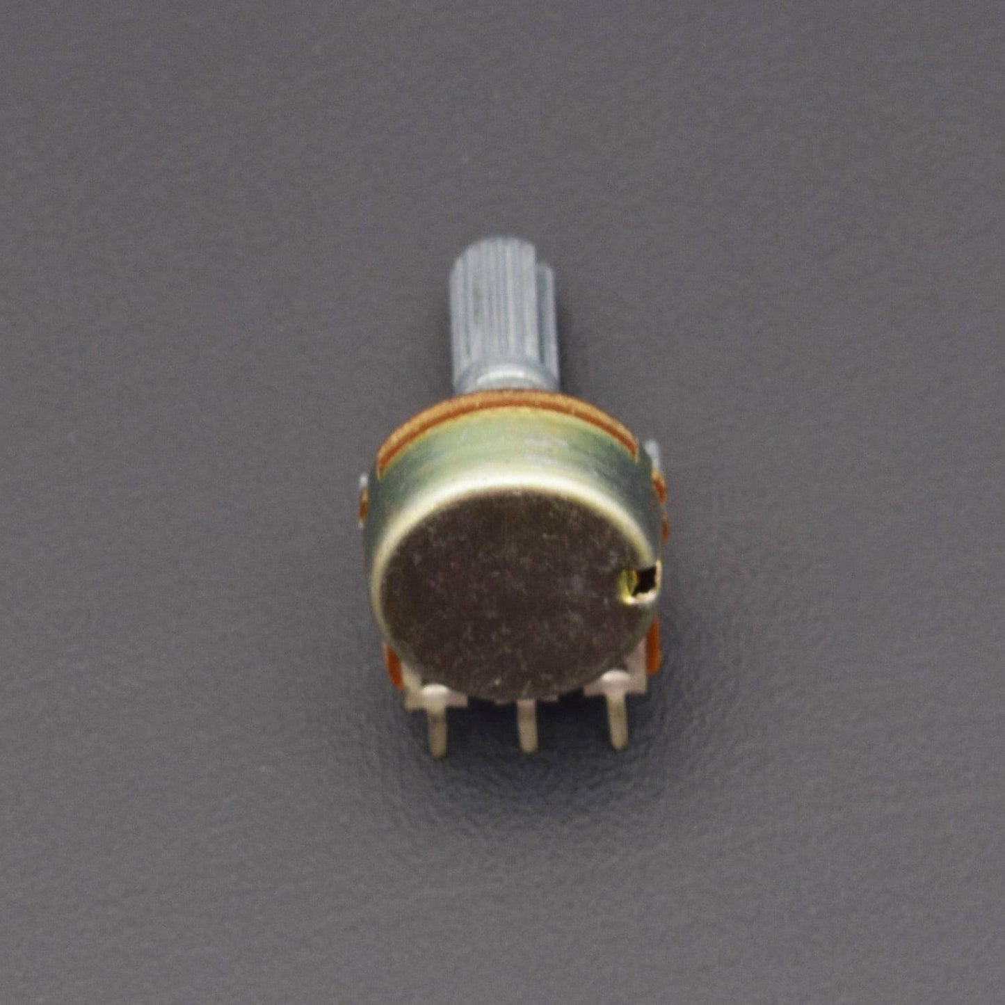
- 10k pot – 1
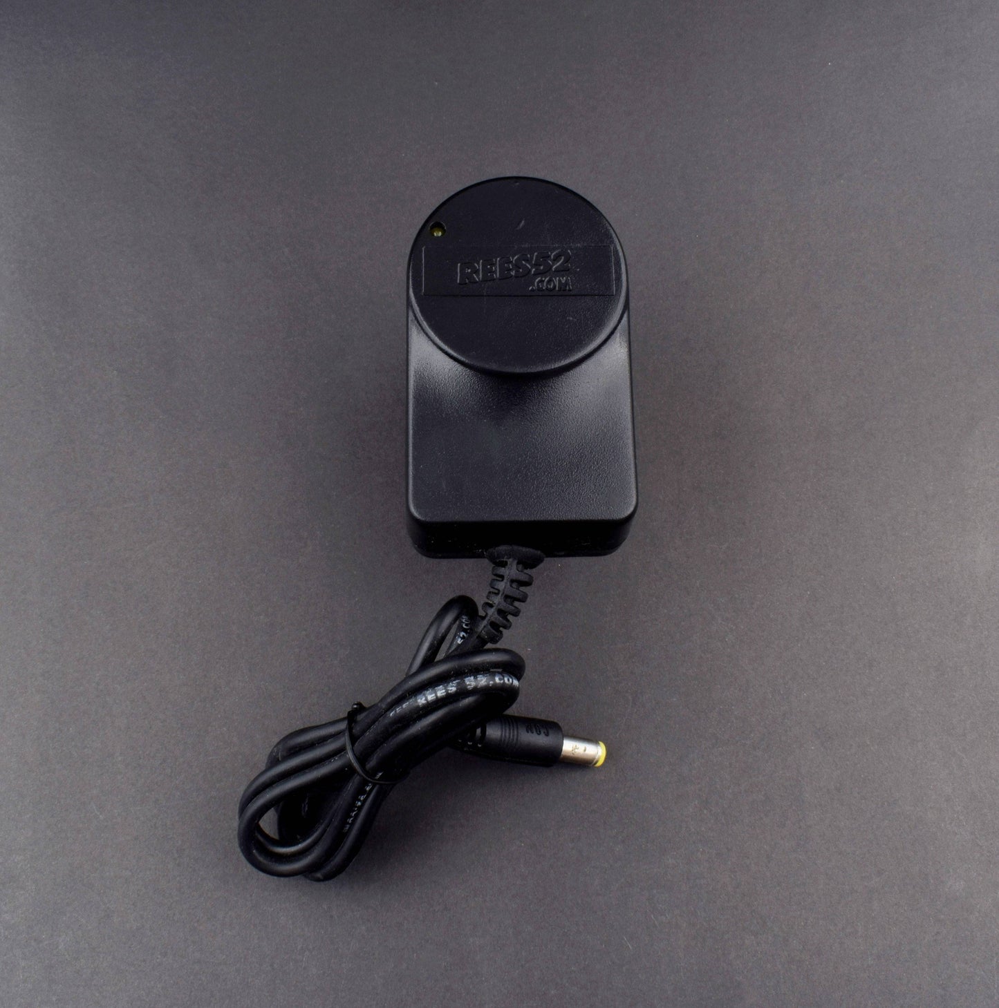
- 5v 1 amp adapter - 1
SOFTWARE REQUIRED
Arduino IDE 1.8.5 (programmable platform for Arduino)
Click To Download :https://www.arduino.cc/en/Main/Software

SPECIFICATIONS
.MQ6 Gas Sensor Module
This is a simple-to-use liquefied petroleum gas (LPG) sensor, suitable for sensing LPG (composed of mostly propane and butane) concentrations in the air. The MQ-6 can detect gas concentrations anywhere from 200 to10000ppm.
- High sensitivity to CH4,Natural gas
- Small sensitivity to alcohol, smoke
- Fast response
- Stable and long life
- Simple drive circuit
.jpg)
CIRCUIT CONNECTION
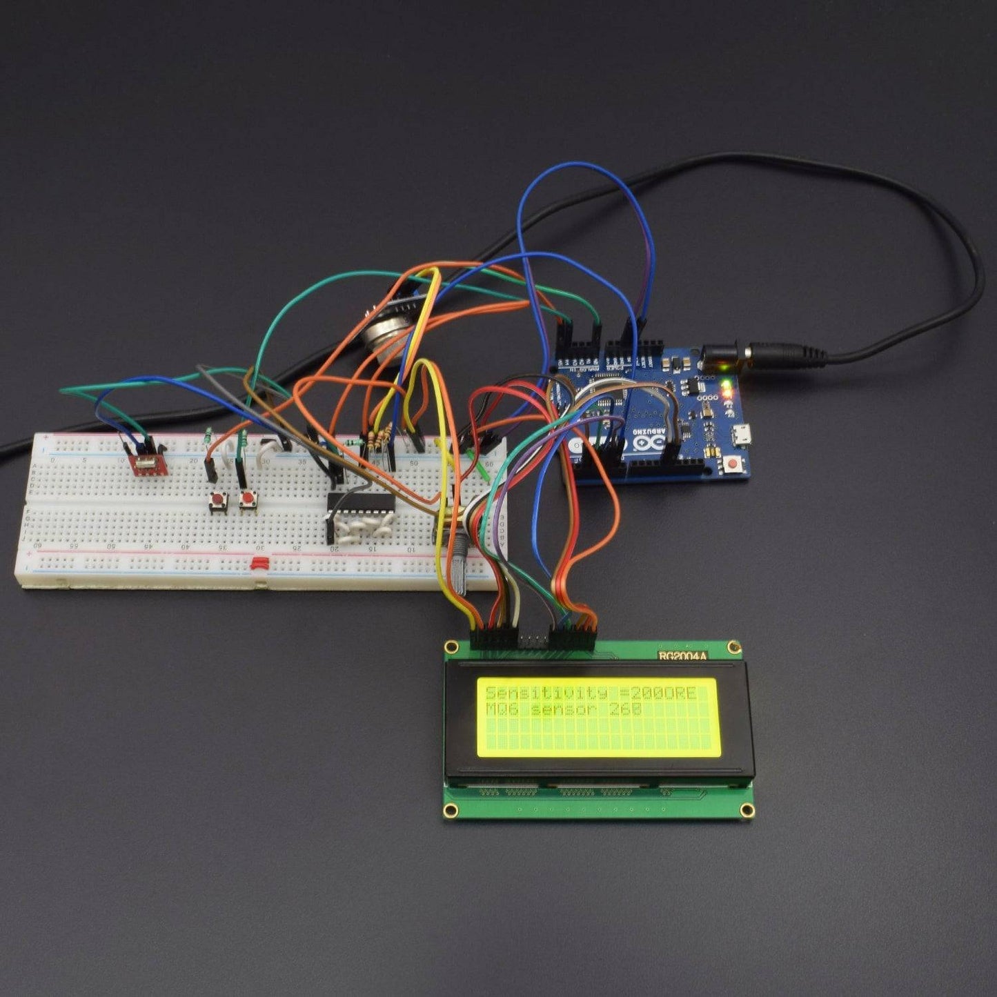
There are two circuits in the project - transmitter circuit and the receiver circuit. The transmitter circuit is built on Arduino UNO and it has MQ6 gas sensor interfaced to it. The circuit is provided human interface using two tactile switches or push button and an LCD display. The circuit is interfaced with the RF transmitter to send alert signals to the receiver circuit.
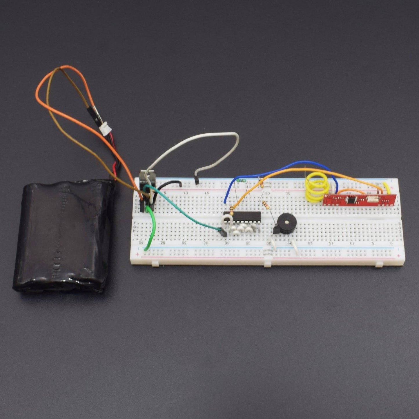
The receiver circuit is basically RF receiver circuit with buzzer circuit interfaced with the decoder IC. More than one receiver circuits can also be made and used with the project to add multiple alarms. All the alarm circuit added in the project will alert simultaneously when there will be a gas leakage. It should be taken care that if multiple alarm circuits are added in the project, all the RF receivers in those circuits should be configured to the same address byte as that of the RF transmitter in the transmitter circuit.
Power Supply - Both the circuits will be powered by 5V DC supply. The 7805 voltage regulator is used to supply the desired voltage. The power can be drawn from a regular battery which can be connected to the 7805 IC. The IC has three pins - pin 1 should be connected to anode of the battery, pin 2 and 3 with the cathode (common ground). The 5V DC should be drawn from the pin 3 of the IC.
The transmitter circuit has the following sections interfaced to it - :
MQ6 Gas Sensor - The MQ6 gas sensor is a gas sensor module. The module has 4 pins for interfacing of which two pins are VCC and ground, one pin is analog output and one pin is digital pin via a comparator (LM358). The analog output pin of the module is used for detecting concentration level of gas leakage and interfaced with the A0 analog input pin of the Arduino board. The sensor measures the concentration of leaked gas in ppm according to the following formulae - :
Concen = 1036.5*R^-2.392 Where
Concen is the concentration of LPG in ppm
R is the ratio of Rs the resistance of sensor to the R0 which is the resistance at 1000ppm at 20 degree Celsius and 65% humidity.
The resistance of the sensor Rs is given by the formulae - :
Rs = (1024/ADC_DATA-1)*RL where
Rs is the resistance of the sensor
ADC_DATA is digital reading ranging from 0 to 1023
RL is load resistance ranging from 10K to 40K ohms
Therefore, for a fixed load resistance, the ADC reading is proportional to the concentration of gas in ppm.
In the datasheet the ratio of concentration to the sensor resistance is given. The graph is done under the normal condition of 20 degree Celsius and 65% humidity. And that means Rs=R0 for the curve.

This way the concentration of gas in ppm becomes equal to ADC reading. The ADC reading will range between 0 and 1023. In the project, the user can set the dangerous level of ADC reading for reference in steps like 200, 250, 300, 350, 400, 450 and 500.
16X2 LCD - The 16X2 LCD display is used to display the increment or selection of sensor's sensitivity. It is connected to the Arduino board by connecting its data pins to pins 2 to 5 of the Arduino board. The RS and E pins of the LCD are connected to pins 13 and 12 of the Arduino UNO respectively. The RW pin of the LCD is grounded.

The standard open-source library for interfacing LCD with Arduino UNO is used in the project. The library works as expected and needs no changes or modifications.
RF Transmitter - The RF transmitter is used to transmit the alert signal to the receiver circuit. The RF transmitter module is a small PCB sub assembly. The pin configuration of transmitter module is as follows - :

The serialized data from encoder is received at pin 2 of the module and passed on to the antenna from pin 4 of the module.
HT12E IC - The HT12E IC converts the parallel data into serial data for passing it to the RF transmitter. HT12E encoder IC belongs to the 212 series of encoders. It is paired with 212 series of decoders having the same number of addresses and data format. HT12E is capable of encoding 12 bits, out of them 8 are address bits and 4 are data bits. Thus the encoded signal is a serialized 12-bit parallel data comprising of 4-bit data to be transferred appended with the address byte.
The receiver circuit is a basic RF receiver with buzzer circuit interfaced to it. The circuit has the following sections -:
Power Supply - The receiver circuit is also powered by the similar 7805 based DC supply as the transmitter circuit.
RF Receiver - The RF receiver detects the radio signal carrying the alert information. The RF receiver module has 8 pins and has following pin configuration.

HT12D Decoder - The signal detected from the RF receiver is passed to the HT12D decoder. It converts the serial data back to the parallel data after separating data and addresses. HT12D belongs to the 212 series of decoders and can be paired with 212 series of encoders having the same number of addresses and data format. HT12D is capable of decoding 12 bits, out of them 8 are address bits and 4 are data bits. The 4-bit data is of latch type and when passed to the output data pins it remains unchanged until the new data is received.
Buzzer - A regular piezoelectric buzzer is used in the receiver circuit. The buzzer is interfaced to D0 bit of the HT12D decoder IC. The buzzer is interfaced through a BC547 transistor connected in common emitter configuration.
CODE
The receiver circuits will not have any programmable controller or IC. The receiver circuits should have the same address byte of the RF receiver configured, as of the transmitter RF module and buzzer sections should be connected to the D0 bits of decoder ICs. The transmitter circuit will have the program code for reading and comparing sensor value and sending RF data to the receiver sections.
First the LCD.h library needs to be imported and an object of LCD class needs to be initialized. An array to contain the predefined reference values also needs to be declared.
WORKING
The MQ6 gas sensor detects concentration of gas in ppm and outputs analog value which can be converted to digital measure using in-built Analog to Digital Convertor of Arduino. The value of the digital measure will be 10-bit long and varies from 0 to 1023. The project allows user to set the dangerous level for leakage based on the same digital measure. When the value set by the user matches with that of the value detected by the sensor, it invokes the alarm. The MQ6 sensor can be calibrated by interfacing a load resistance of fixed value with the sensor.
1) Setting the sensitivity level - When the transmitter device is switched ON, the Arduino board loads the imported libraries and initializes LCD display. Some initial messages are displayed on the LCD and after 3 seconds the user is prompted to set the sensitivity level. The user can increase the sensitivity level in increments of 200, 250, 300, 350, 400, 450 and 500 by pressing one switch. On pressing the switch the value for reference increases then decreases repeatedly. Each value corresponds to concentration level in PPM. On pressing other switch, the sensitivity value is set for the reference.
2) Monitoring Gas Concentration - Once the reference value is set, the program code on Arduino keeps track of the analog value read from the MQ6 sensor. The device is programmed to read current sensor reading asanalog value and convert it to a digital form. The digital measure is compared with the user defined reference value in an infinite loop.
3) Sending Danger Alert - If the current value measured from the sensor equals or exceeds the user defined reference value, the transmitter device is programmed to set the pin 6 of Arduino board HIGH. The pin 6 of the Arduino is connected to D0 bit of the encoder IC. Therefore, the RF transmitter starts transmitting the 0x1 as the data bit. The same bit is decoded as HIGH logic at the D0 bit of the decoder IC. When a HIGH bit is received at D0 bit, the buzzer circuit get the required supply and starts blowing. It should be taken care that in every receiver alarm circuit of the project, all the address bytes should be same as the address byte of the transmitter circuit and the buzzer section in the respective receiver circuit(s) should be connected at the D0 pins of the respective decoder ICs.