
Kit includes
- Arduino UNO with USB cable – 1
- 400 point breadboard – 1
- Red led– 2 Pieces
- Yellow Led - 2 Pieces
- green led - 2 Pieces
- Resistor 220 ohm – 5
- Jumper wires (male to male) – 20 pieces
Introduction
In this project we are making a Traffic Light System which consists of the LEDs for making a simulation of traffic lights, the blinking time of each LED should be the same with those in the traffic lights system.
HARDWARE REQUIRED
- Arduino uno with Usb cable – 1
- 400 point breadboard – 1
- Red led– 2 Pieces
- Yellow Led - 2 Pieces
- green led - 2 Pieces
- Resistor 220 ohm – 5
- Jumper wires (male to male) – 20 pieces
SOFTWARE REQUIRED
Arduino IDE (Programmable Platform for Arduino)
CLICK TO DOWNLOAD: https://www.arduino.cc/en/Main/Software
PIN DESCRIPTION
LED

CIRCUIT DIAGRAM

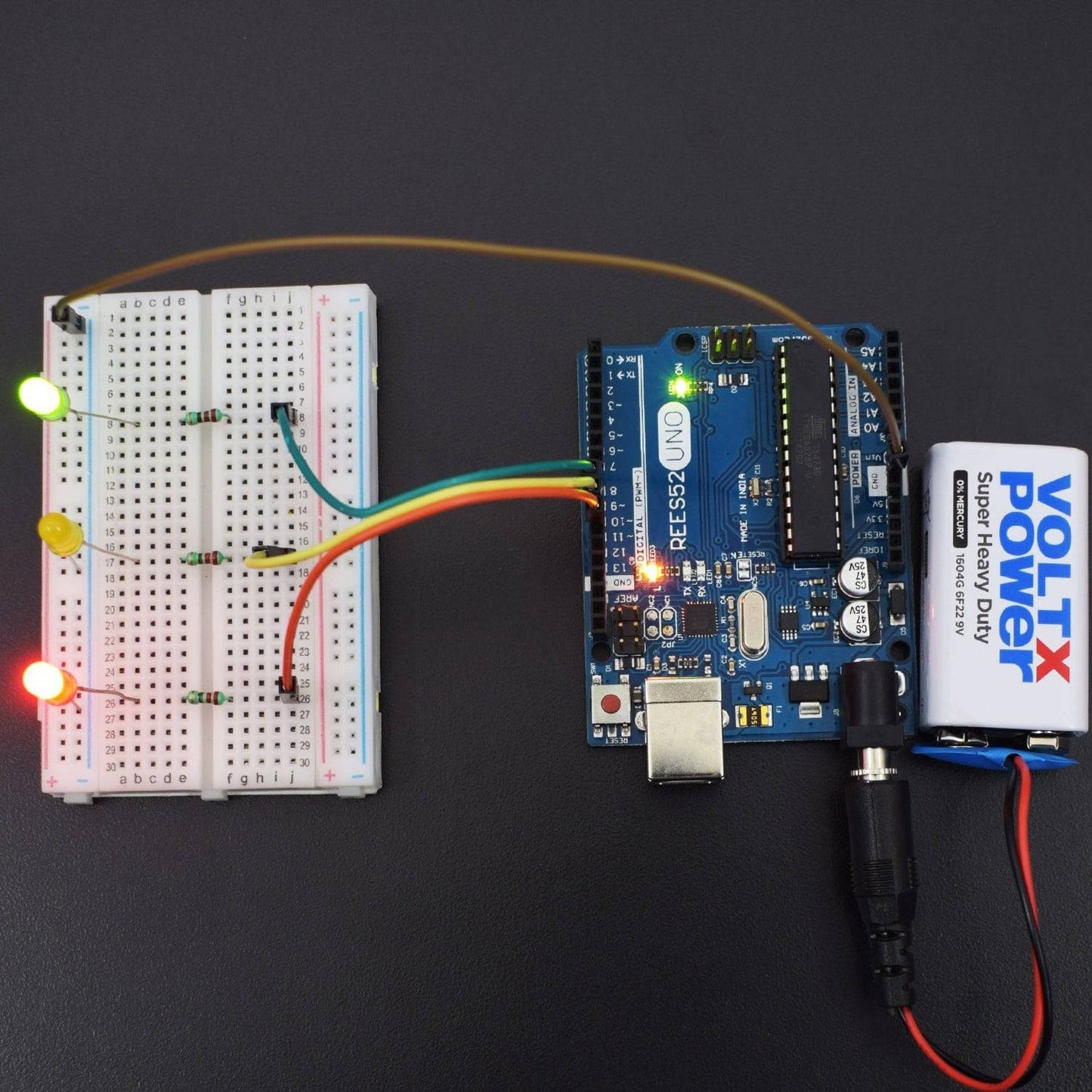
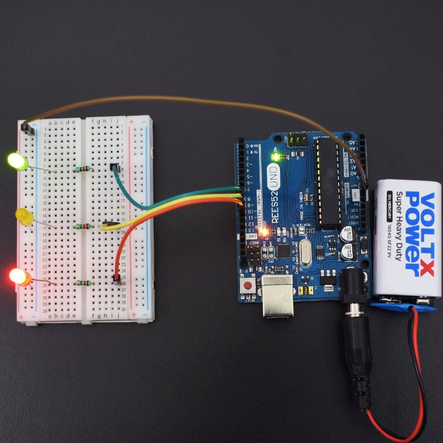
- connect all the negative of the leds then connect to the ground pin of Arduino UNO
- Positive of green Led to Arduino’s digital pin 8 via 220-ohm resistor adding on the positive terminal of led.
- Positive of Yellow Led to Arduino’s digital pin 9 via 220-ohm resistor adding on the positive terminal of led.
- Positive of Red Led to Arduino’s digital pin 10 via 220-ohm resistor adding on the positive terminal of led.
CODE
Click to see the code or copy the link:
WORKING
Welcome to the Arduino Based Project which consists of the LEDs for making a simulation of traffic lights, the blinking time of each LED should be the same with those in the traffic lights system. In the program, we use Arduino delay () function to control delay time.
So, when the uploading process is completed, we can see the traffic lights of our own design. The green light will be on for 5 seconds, and then off., followed by the yellow light blinking for 3 times, and then the red light on for 5 seconds, forming a cycle. And the Cycle repeats.


