


vendor-unknown
Make a temperature controller Automatic switch using LM35 Temperature Sensor and 1 Channel 5V relay Module - kt869
Make a temperature controller Automatic switch using LM35 Temperature Sensor and 1 Channel 5V relay Module - kt869
SKU:KT869
1000 in stock
Couldn't load pickup availability
- For Bulk Order Click Here
- Need Customer Support?
- Free Delivery Above 999/-
Note: In case you receive a damaged or faulty product, please return it in the original box with all foam and packaging. Returns will not be accepted if further damage occurs due to improper packing.
If you order a product that is currently in Preorder, and the price of that item increases in the future, you will be required to pay the difference in price.
For refund/return/replacement, call us at +91 95995 94520 or email us at support@rees52.com
Delivery Time
Delivery Time
- Delivery time with the Express Shipping option is 2-3 working days, and with the Standard Shipping option is 5-6 working days. It varies based on location, reliant on courier services.
- Delivery time if the order item is on Preorder Status is 15-20 working days.
COD (Cash on Delivery)
COD (Cash on Delivery)
- For COD you have to pay extra charges of Rs 350/- before the shipment. (We will share the company QR Code, UPI ID or Account details for the same)


KIT INCLUDES:

HARDWARE REQUIRED
- Arduino uno with USB cable - 1
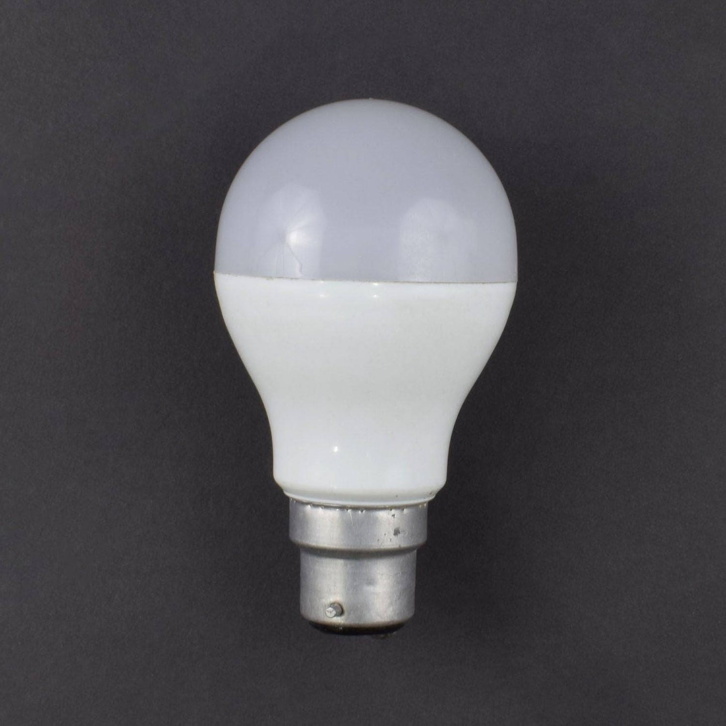
- Bulb – 2 (not included in kit)
- 5v 4 channel relay – 1
- 16*2 lcd – 1
- 5v adapter -1
- Bread board 400 point- 1
- TSOP SENSOR - 1
- Potentiometer 10k - 1
- TSOP remote – 1
- Bulb Holder with wire – 2 (not included in kit)
- Jumper wire (male to male & male to female)-40 pieces each
- Single stand wire 2m - 1
PIN DESCRIPTION
5v relay module
- Number of I/O Channels: 1
- Type: Digital
- Control signal: TTL level
- Max. Allowable Voltage: 250VAC/110VDC
- Max. Allowable Power Force: From C(800VAC/240W), From A(1200VA/300W)

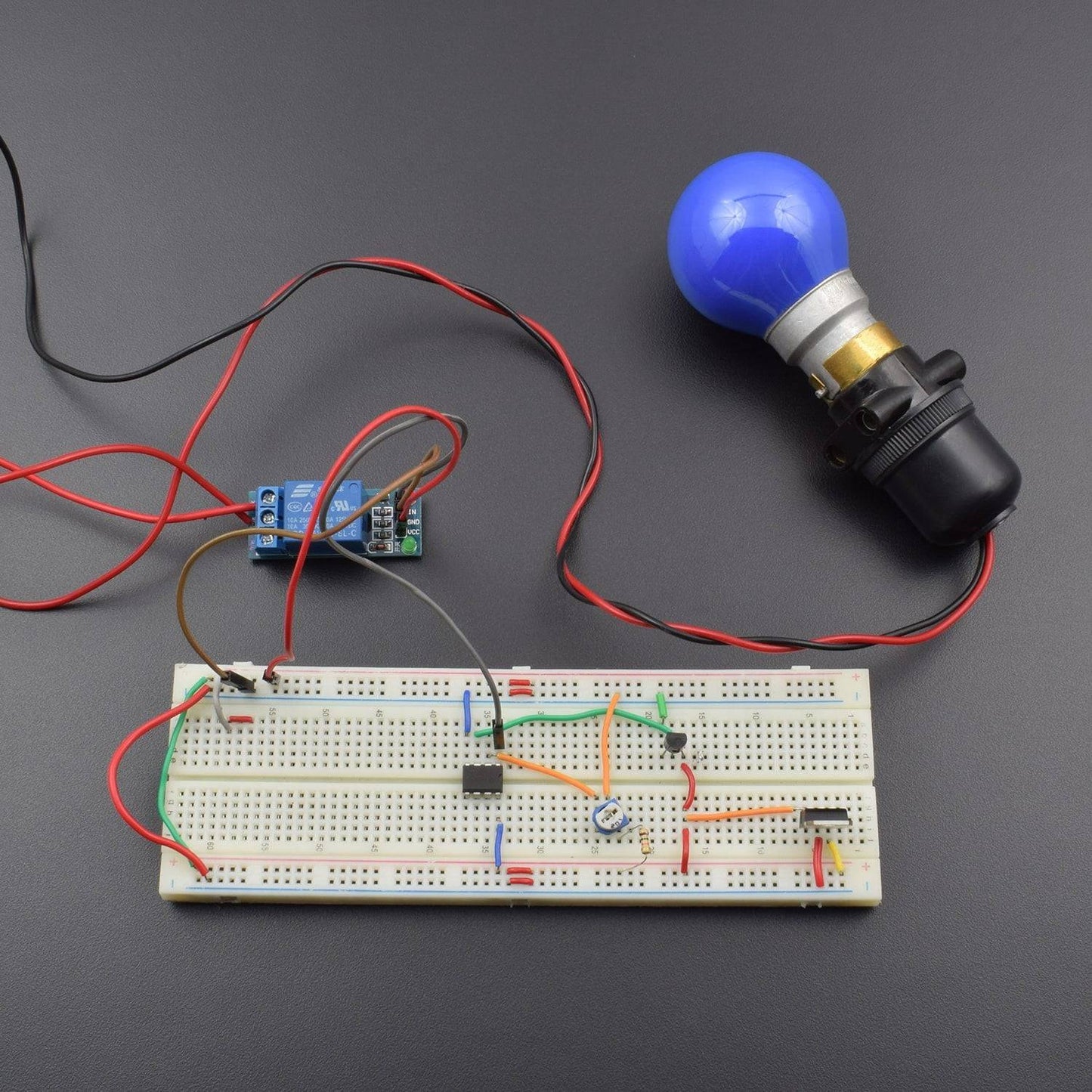
CIRCUIT DESCRIPTION

- 7805 voltage regulator IC and LM35 temperature sensor connected to the breadboard.
- 7805 IC 1st pin connected to the positive supply, 2nd pin connected to the negative supply and 3rd pin connected to the LM35 temperature sensor 1st pin.
- LM35 first pin connected to the positive supply and 3rd pin connected to the negative supply.
- LM35 2nd pin is connected to the LM358 IC pin no. 3.
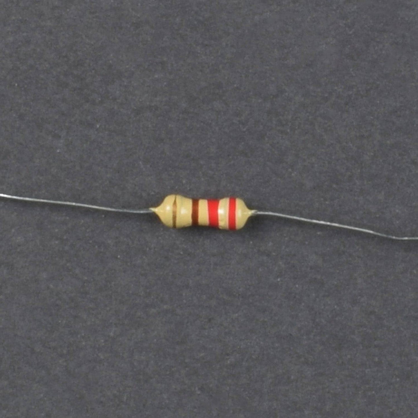
- 10K resistor 1st leg is connected to the positive supply and 2nd leg connected to the 10K pot 1st leg.
- 10K 2nd leg is connected to the negative supply and 10K middle leg is connected to the 358 IC pin no. 2.
- LM 358 IC pin no 4 is connected to the negative supply and pin no.8 is connected to the positive supply.
- 5 volt single channel relay module we connect on bread boardvcc to vcc ,gnd to gnd, input of relay module connect to the LM358 PIN NO 1 and we connect no & nc point of relay to ac 220volt.
- we connect the both point of bread board positive to positive & negative to negative point to provide the supply both side of the bread board.
WORKING
Control Home AC appliances according to Temperature. This circuit will serve as automatic light switch which will trigger if temperature goes beyond a particular level (50 Degree in this circuit). We are using LM35 as temperature sensor here. This threshold temperature of 50 degree value can be changed by adjusting the Variable resistor in the circuit, according to requirement.
We have used a simple LED bulb in this Temperature Controlled Switch Circuit for demonstration, means if temperature goes above than 50 Degree Celsius then bulb will switch on automatically and if temperature goes below 50 degree, bulb will be switched off automatically. Here you can replace the bulb by any AC home appliance, like if you replace it by fan then it will serve as Temperature Controlled Fan Circuit. It can also work as fire alarm if you set the threshold temperature very high like 100 Degree Celsius and connect a alarm in place of bulb or you can configure it to automatically switch on the Air Conditioner beyond a particular temperature by using a Relay of proper rating.
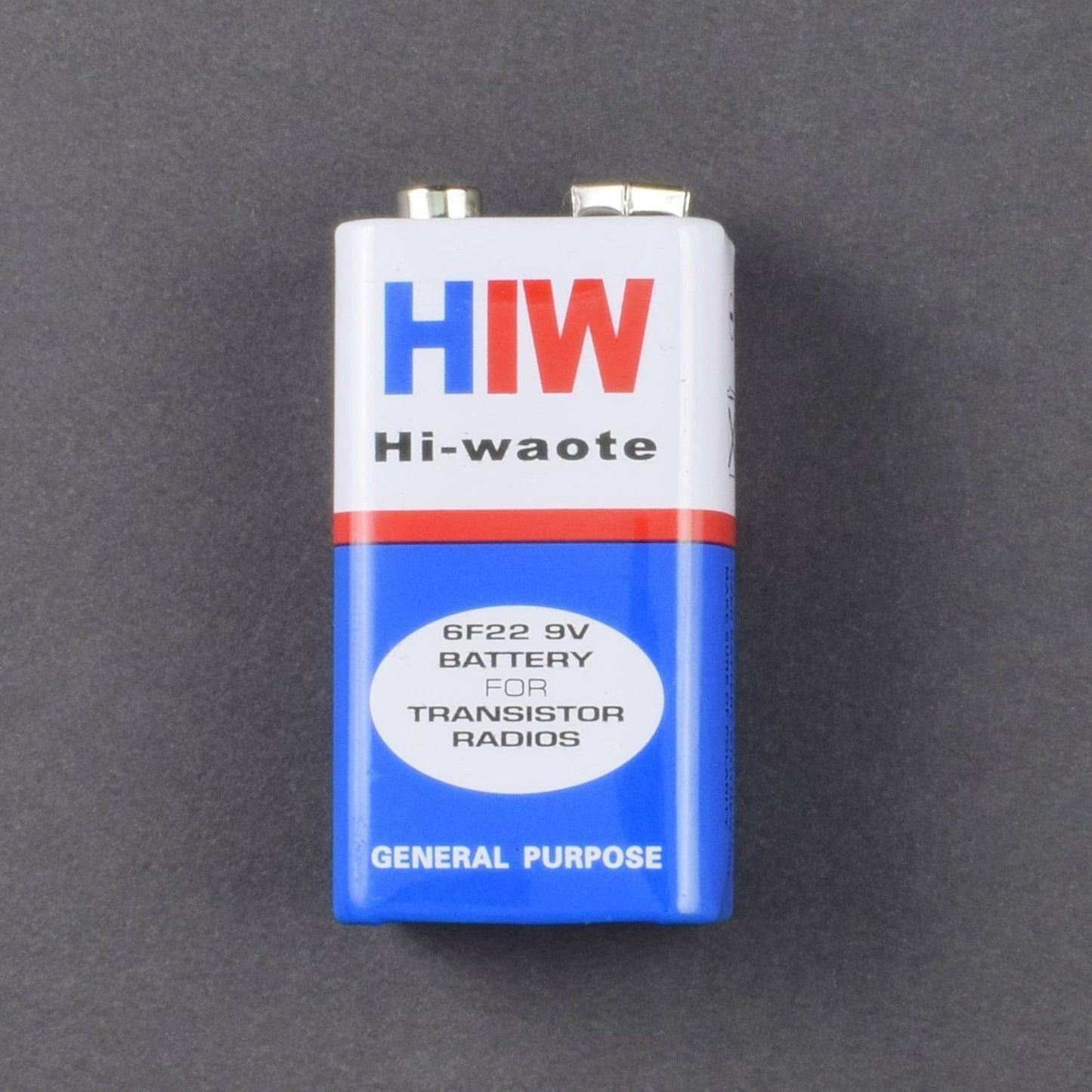
Working of this Temperature Controlled Home Appliances Circuit is simple. 9v general purpose battery is used to power up the whole circuit and IC7805 is used to provide the regulated 5v supply to the circuit. When temperature is below 50 degree then output of LM358 remains LOW and transistor Q1 & Relay also remain in OFF state, thus bulb is off. You can set this threshold temperature accordingly by rotating the POT.
Now when surrounding’s temperature goes beyond 50 Degree Celsius, output voltage of LM35 at pin 2 also goes higher than 0.5 volt or 500mV. Output of LM35 is connected to Pin 3 of Op-amp LM358. And as we have set the reference voltage (voltage at Pin 2 of LM358) to 0.5 volt, so now voltage at Pin 3 (non-inverting input) becomes higher than voltage at Pin 2 (inverting input) and output of op-amp LM358 (PIN 1) becomes HIGH. Output of LM358 is connected to the base of NPN transistor Q1, so Q1 also becomes ON which triggers the Relay and bulb gets turned ON. Relay has small coil inside which get energies by small current and trigger the AC device connected to it, we have explained its working below. So that’s how this circuit detects the temperature limit and automatically switch on the Appliances.
In the demonstration video, we have used soldering iron to heat up the surrounding near Temperature sensor LM35, check the video at the end. Also here we are working with direct AC mains of 220v, so extreme care must be taken, otherwise you may have a serious injury.