


vendor-unknown
Make a Temperature Controlled Fan using DHT22 and 16*2 LCD interfacing with Arduino uno - KT820
Make a Temperature Controlled Fan using DHT22 and 16*2 LCD interfacing with Arduino uno - KT820
SKU:KT820
1000 in stock
Couldn't load pickup availability
- For Bulk Order Click Here
- Need Customer Support?
- Free Delivery Above 999/-
Note: In case you receive a damaged or faulty product, please return it in the original box with all foam and packaging. Returns will not be accepted if further damage occurs due to improper packing.
For refund/return/replacement, call us at +91 95995 94520 or email us at support@rees52.com
Delivery Time
Delivery Time
- Delivery time with the Express Shipping option is 2-3 working days, and with the Standard Shipping option is 5-6 working days. It varies based on location, reliant on courier services.
- Delivery time if the order item is on Preorder Status is 15-20 working days.
COD (Cash on Delivery)
COD (Cash on Delivery)
- For COD you have to pay extra charges of Rs 350/- before the shipment. (We will share the company QR Code, UPI ID or Account details for the same)
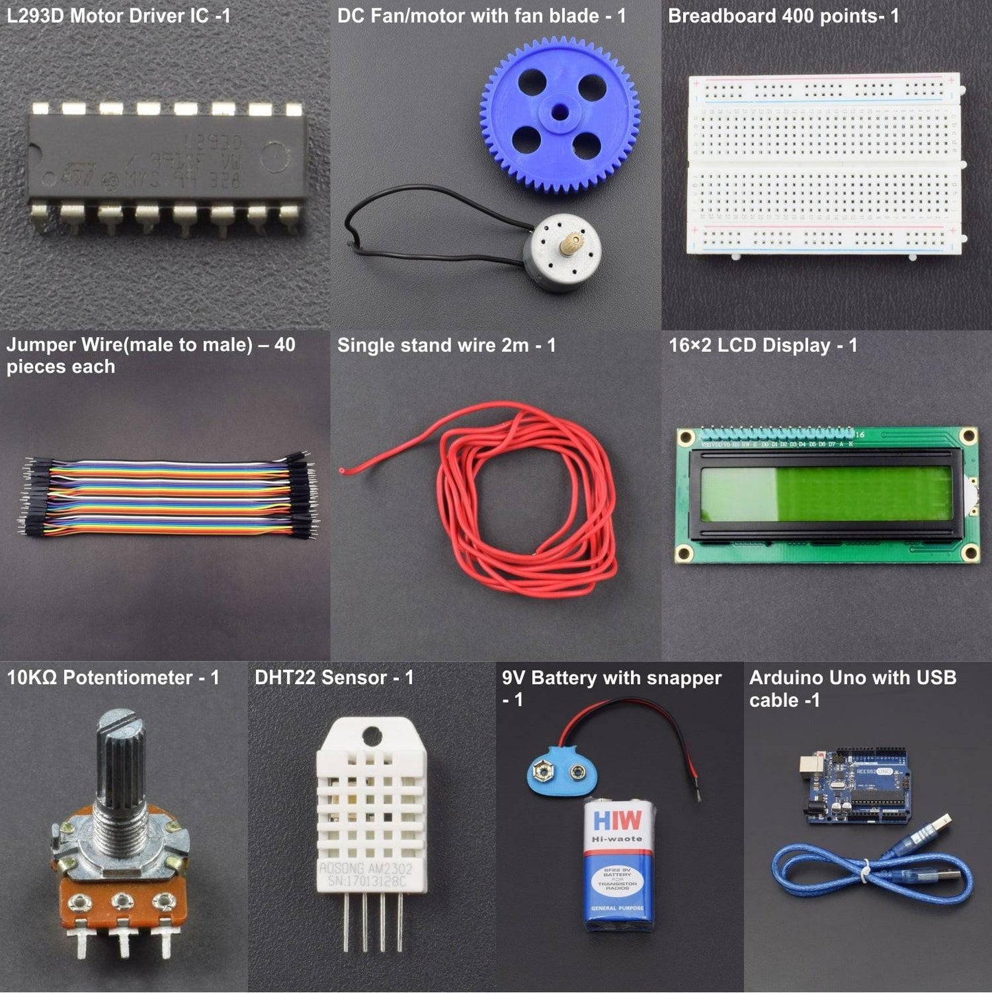
KIT INCLUDES:
- Arduino Uno with USB cable -1
- L293D Motor Driver IC -1
- DHT22 Sensor - 1
- 16×2 LCD Display - 1
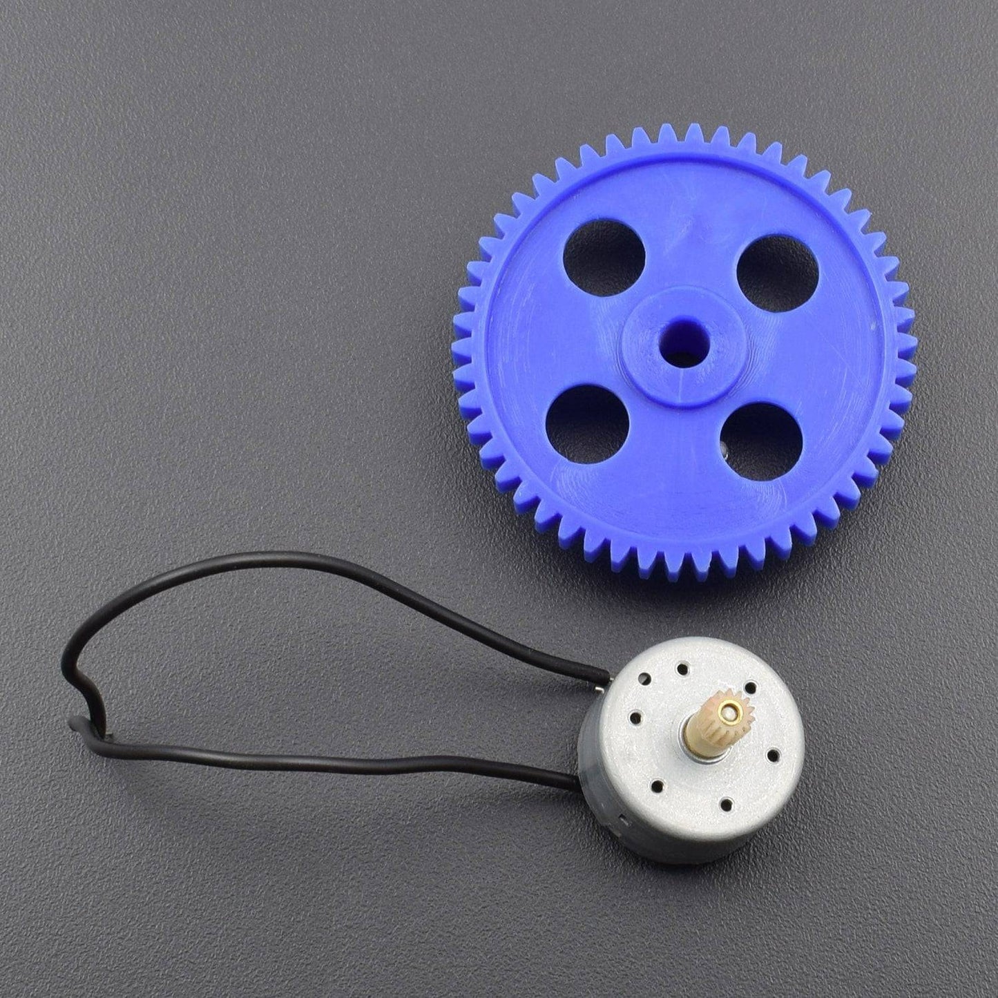
- DC Fan/motor with fan blade - 1
- 9V Battery with snapper - 1
- 10KΩ Potentiometer - 1
- Breadboard 400 points- 1
- Jumper Wire(male to male) – 40 pieces
- Single stand wire 2m - 1
HARDWARE REQUIRED
- Arduino Uno with USB cable -1
- L293D Motor Driver IC -1
- DHT22 Sensor - 1
- 16×2 LCD Display - 1
- DC Fan/motor with fan blade - 1
- 9V Battery with snapper - 1
- 10KΩ Potentiometer - 1
- Breadboard 400 points- 1
- Jumper Wire(male to male) – 40 pieces
- Single stand wire 2m - 1
SOFTWARE REQUIRED
Arduino IDE 1.8.5 (programmable platform for Arduino)
Click To Download :https://www.arduino.cc/en/Main/Software

SPECIFICATIONS
16*2 LCD Display
- LCD Display Mode: STN, Positive, Transflective
- Display Color: Deep Blue/ Yellow Green
- Viewing Angle: 6H
- Driving Method : 1/16 duty, 1/5 bias
- Back Light : Yellow-Green LED backlight
- Outline Dimension: 803615.8 MAX
PIN DESCRIPTION
10 K Potentiometer

16*2 LCD Display


DHT22 Sensor
- 3 to 5V power and I/O
- 2.5mA max current use during conversion (while requesting data)
- Good for 0-100% humidity readings with 2-5% accuracy
- Good for -40 to 125°C temperature readings ±0.5°C accuracy
- No more than 0.5 Hz sampling rate (once every 2 seconds)
- Body size 15.1mm x 25mm x 7.7mm
- 4 pins with 0.1" spacing


CIRCUIT DESCRIPTION

- Connect pin 1 (Enable 1) of L293D to pin 5 of Arduino.
- Connect pin 2 (Input 1) of L293D to the pin 4 of Arduino.
- Connect pin 3 (Output 1) of L293D to one terminal of the DC motor.
- Pins 4 and 5 of the L293D are ground pins, connect these to common ground (battery ground + arduino ground).
- Connect pin 6 (Output 2) of L293D to the remaining terminal of the DC motor.
- Connect pin 7 (Input 2) of L293D to the pin 3 of Arduino.
- Pin 8 is Vcc2, which is the driver/motor power input, connect it to positive of the battery.
- Pin 16 is Vcc1, which is logic voltage input (voltage level of control signals provided by Arduino). Connect it to 5V output of Arduino.
- After that connect DHT22 sensor to the Arduino, it is using a single wire bus for communication.
- First pin is VCC power input, connect it to 5V output of Arduino.
- Second pin is DATA output, connect it to pin 6 of Arduino.
- Third pin is NOT USED.
- Fourth pin is Ground, connect it to ground.
- Now we can connect 16×2 LCD to the Arduino.
- Pin 1 is VSS, connect it to ground.
- Pin 2 is VDD, connect it to 5V output of Arduino.
- Pin 3 is VEE, for adjusting display contrast. Connect it to the variable terminal of a potentiometer whose fixed terminals are connected to ground and 5V.
- Pin 4 is RS (Register Select), it is used to select data or command register. Connect it to pin 12 of Arduino.
- Pin 5 is R/W (Read/Write). Connect it to ground since we are only writing data to LCD in this project.
- Pin 6 is EN (Enable), it is used to indicate a valid data/command in data lines (D0 ~ D7). Connect it to pin 11 of Arduino.
- Pin 7 ~ 10 are data pins (D0 ~ D3), used to transmit data/command to LCD controller. But these pins are not used in 4 bit LCD interfacing, so connect it to ground.
- Pin 11 ~ 14 are data pins (D4 ~ D7), used to transmit data/commands to LCD controller. Connect it to Arduino pins 10, 9, 8 and 7 respectively.
CODE
- Download DHT Library from here : .
- Open Arduino IDE.
- Go to Sketch >> Include Library >> Add .ZIP Library
- Select the downloaded ZIP file and press Open.
CODE:
WORKING
DHT22 sensor is used to read the temperature to control fan speed. It can even read relative humidity also. This sensor is very easy to use and having very good accuracy compared to other sensors. We are using L293D motor driver IC for controlling DC fan/motor with Arduino. It can drive 2 DC motors and we can also control the speed by providing PWM signals.
In the program we have set four different conditions to run the DC fan. If the temperature is less than 25°C, then the DC fan will remain off and details will be displayed on the LCD. If the temperature is between 25°C and 30°C, then the DC fan will start working at low speed (30% duty cycle). Similarly if the temperature is between 30°C and 35°C, then the DC fan will run at a medium speed (60% duty cycle). If the temperature is greater than or equal to 35°C, then the DC fan will run at full speed (100% duty cycle).