


vendor-unknown
Make A Temperature Controlled Dc Fan Using Thermistor And Lm 741 IC - KT859
Make A Temperature Controlled Dc Fan Using Thermistor And Lm 741 IC - KT859
SKU:KT859
98 in stock
Couldn't load pickup availability
- For Bulk Order Click Here
- Need Customer Support?
- Free Delivery Above 999/-
Note: In case you receive a damaged or faulty product, please return it in the original box with all foam and packaging. Returns will not be accepted if further damage occurs due to improper packing.
If you order a product that is currently in Preorder, and the price of that item increases in the future, you will be required to pay the difference in price.
For refund/return/replacement, call us at +91 95995 94520 or email us at support@rees52.com
Delivery Time
Delivery Time
- Delivery time with the Express Shipping option is 2-3 working days, and with the Standard Shipping option is 5-6 working days. It varies based on location, reliant on courier services.
- Delivery time if the order item is on Preorder Status is 15-20 working days.
COD (Cash on Delivery)
COD (Cash on Delivery)
- For COD you have to pay extra charges of Rs 350/- before the shipment. (We will share the company QR Code, UPI ID or Account details for the same)

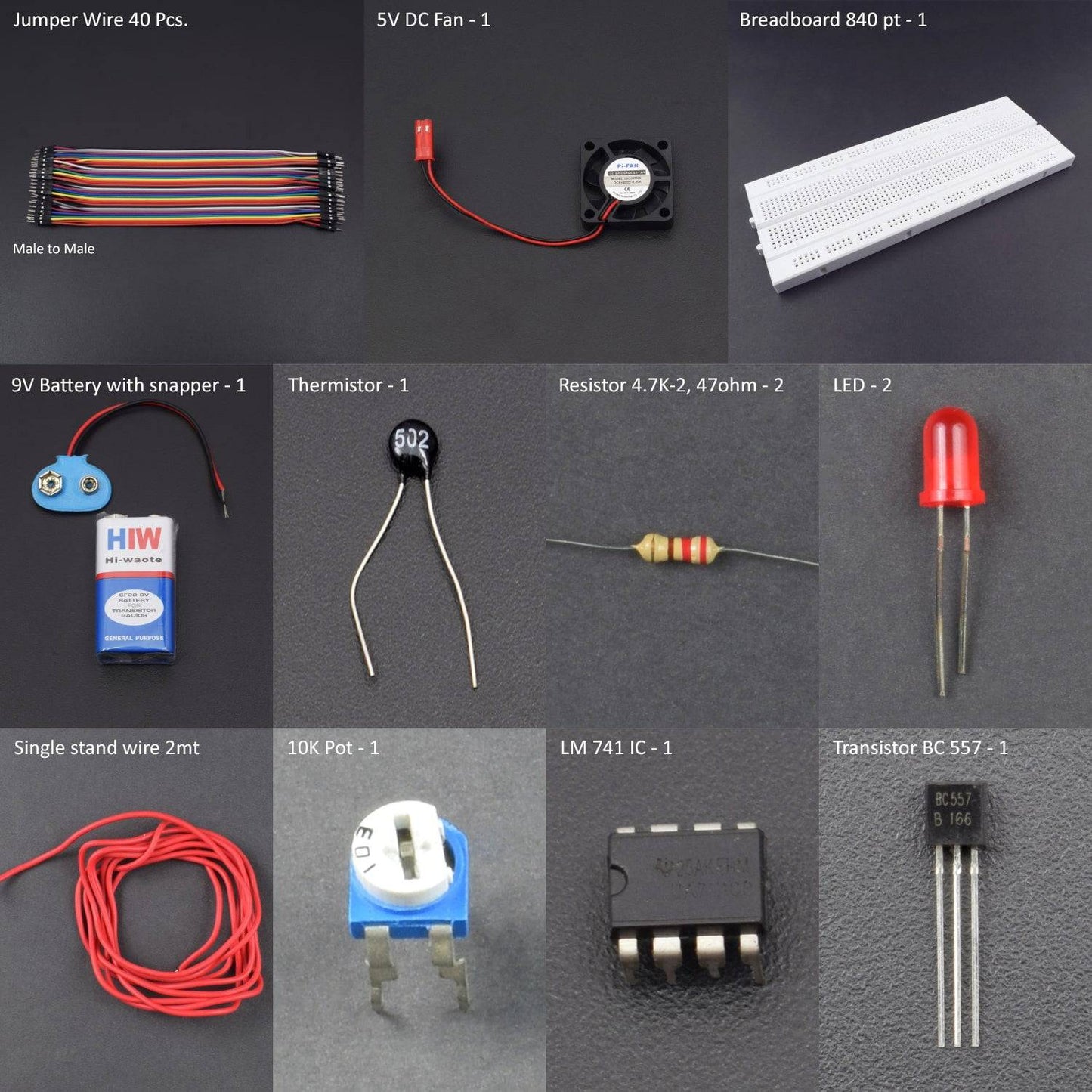
KIT INCLUDES:
- LM 741 IC - 1
- Thermistor - 2
- Transistor BC 557 - 2
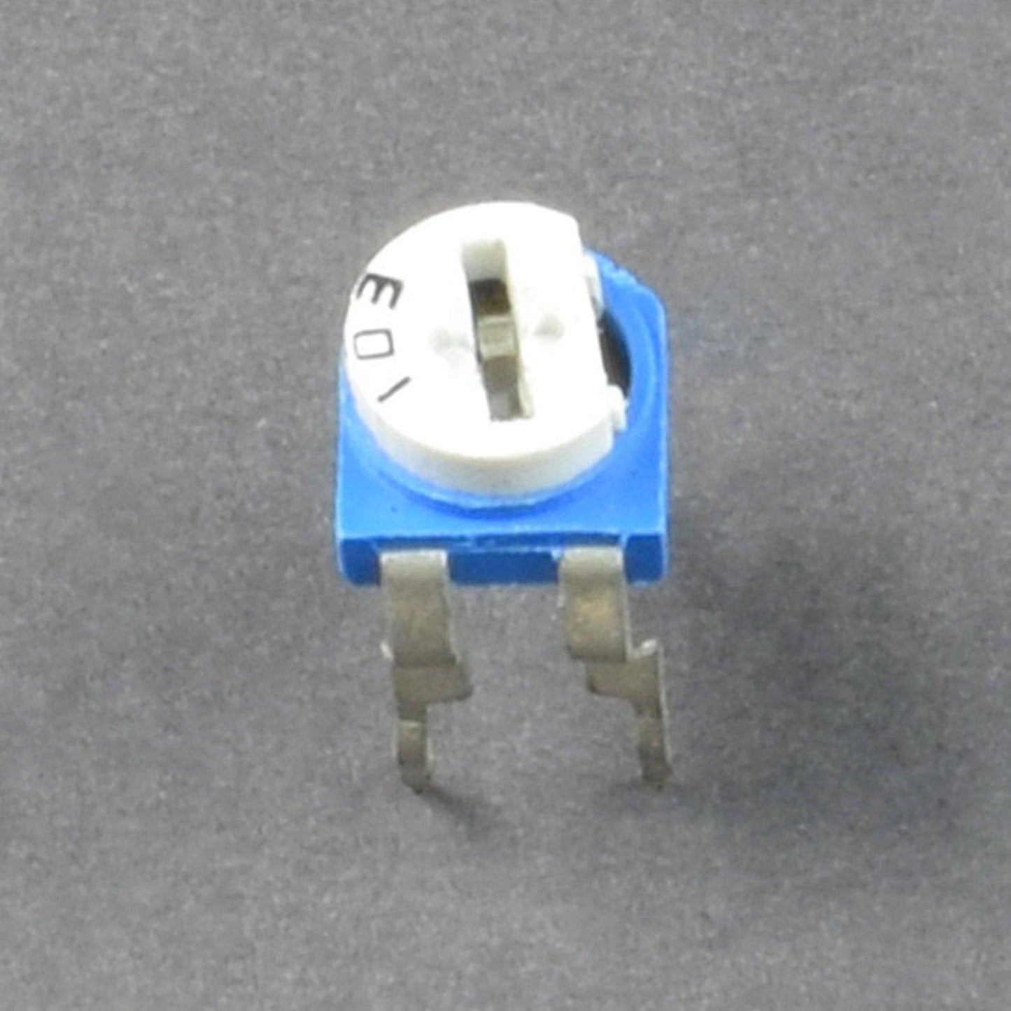
- 10K Pot - 1
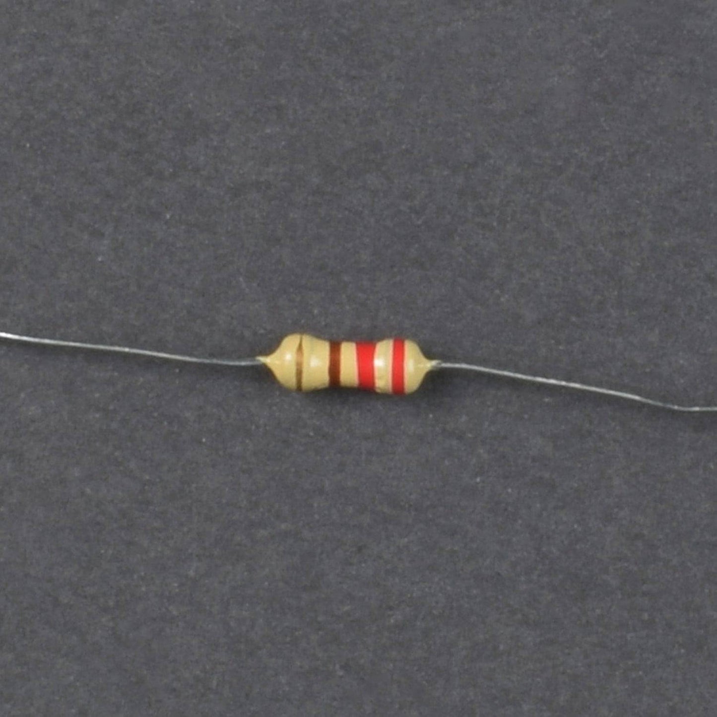
- Resistor 4.7K-2, 47ohm-2
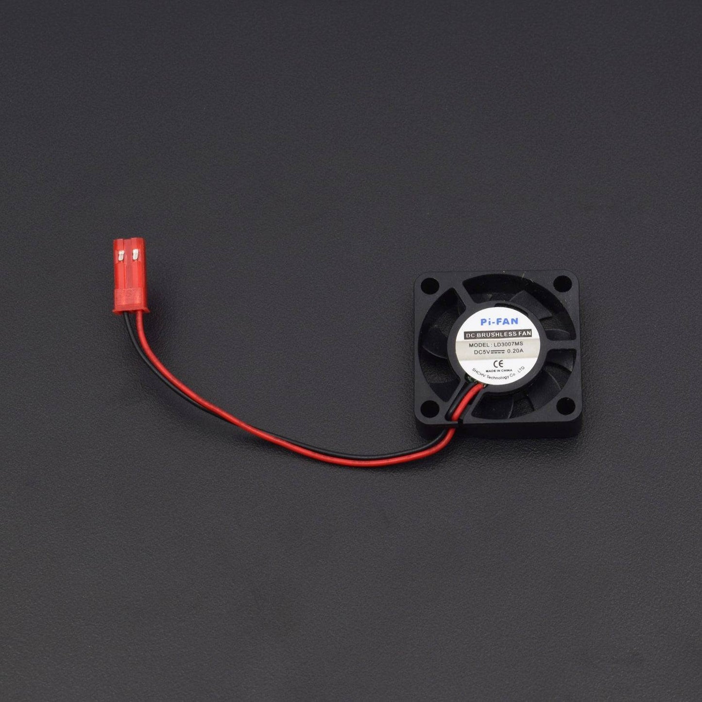
- 5V DC Fan - 1
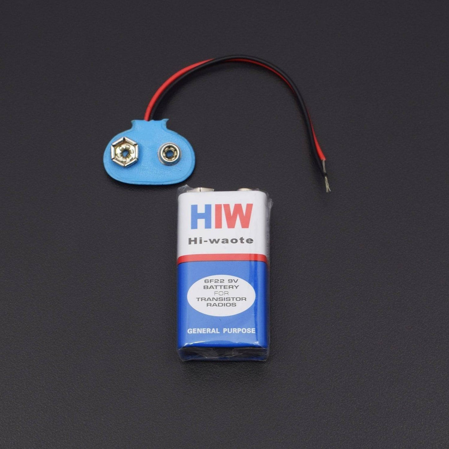
- Battery 9V with snapper- 1
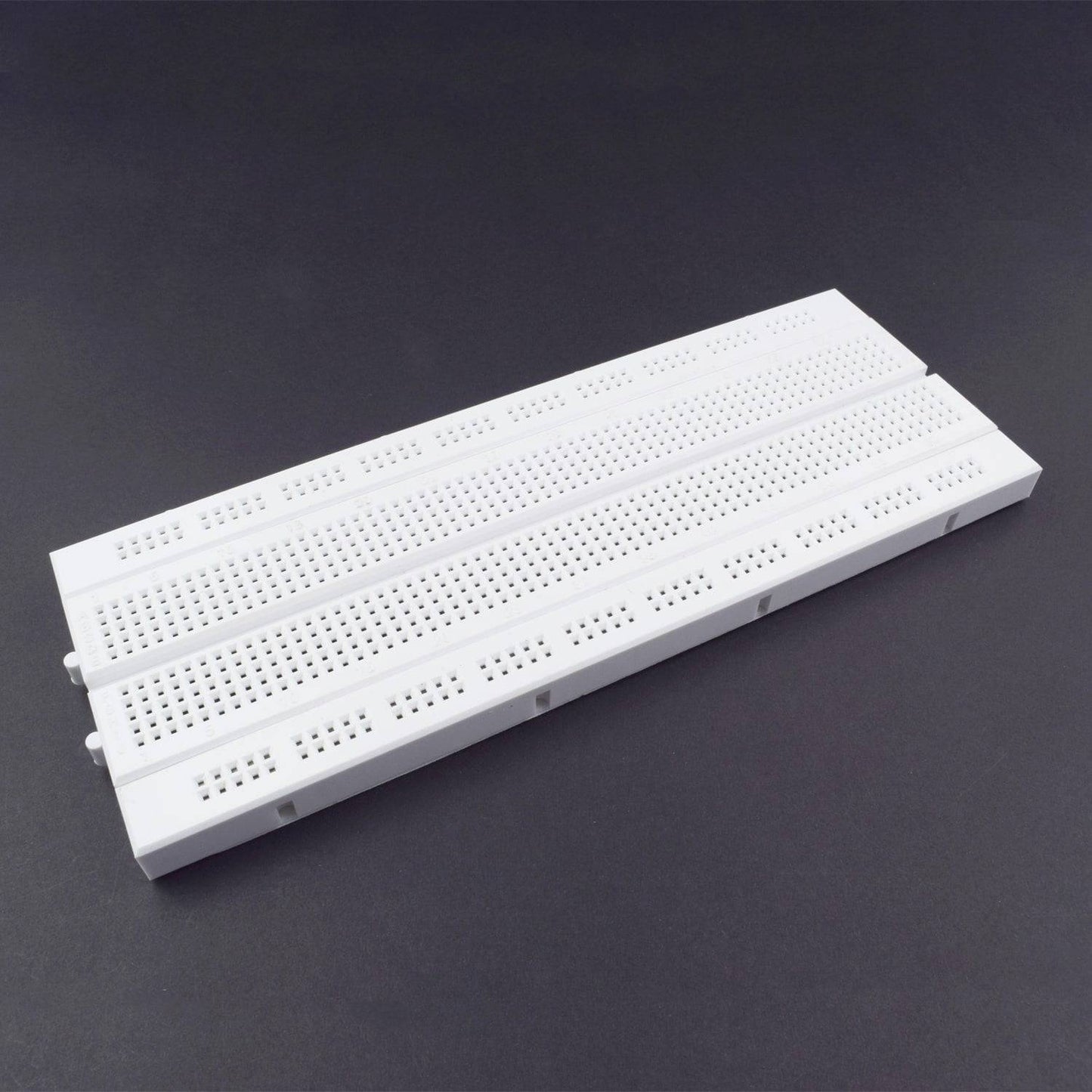
- Breadboard 840 POINTS - 1
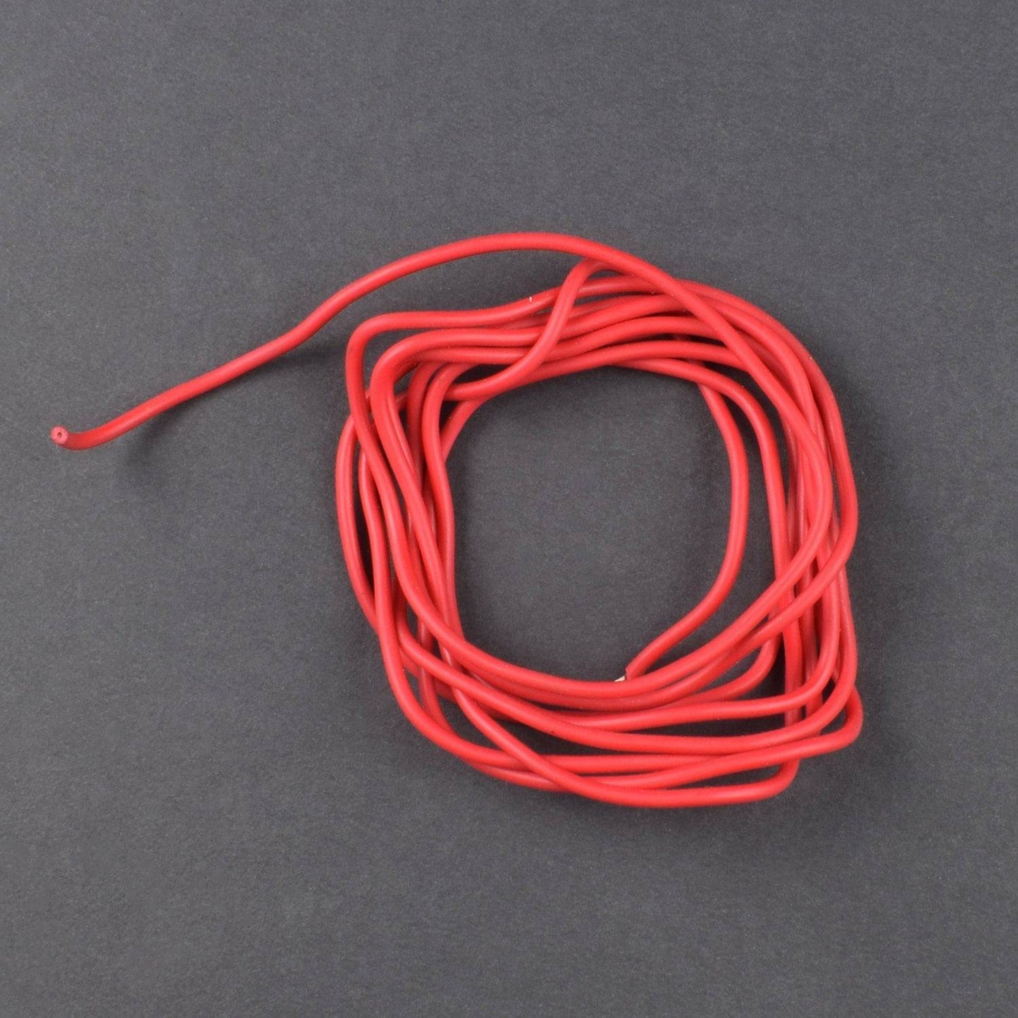
- Single stand wire 2 meter – 1
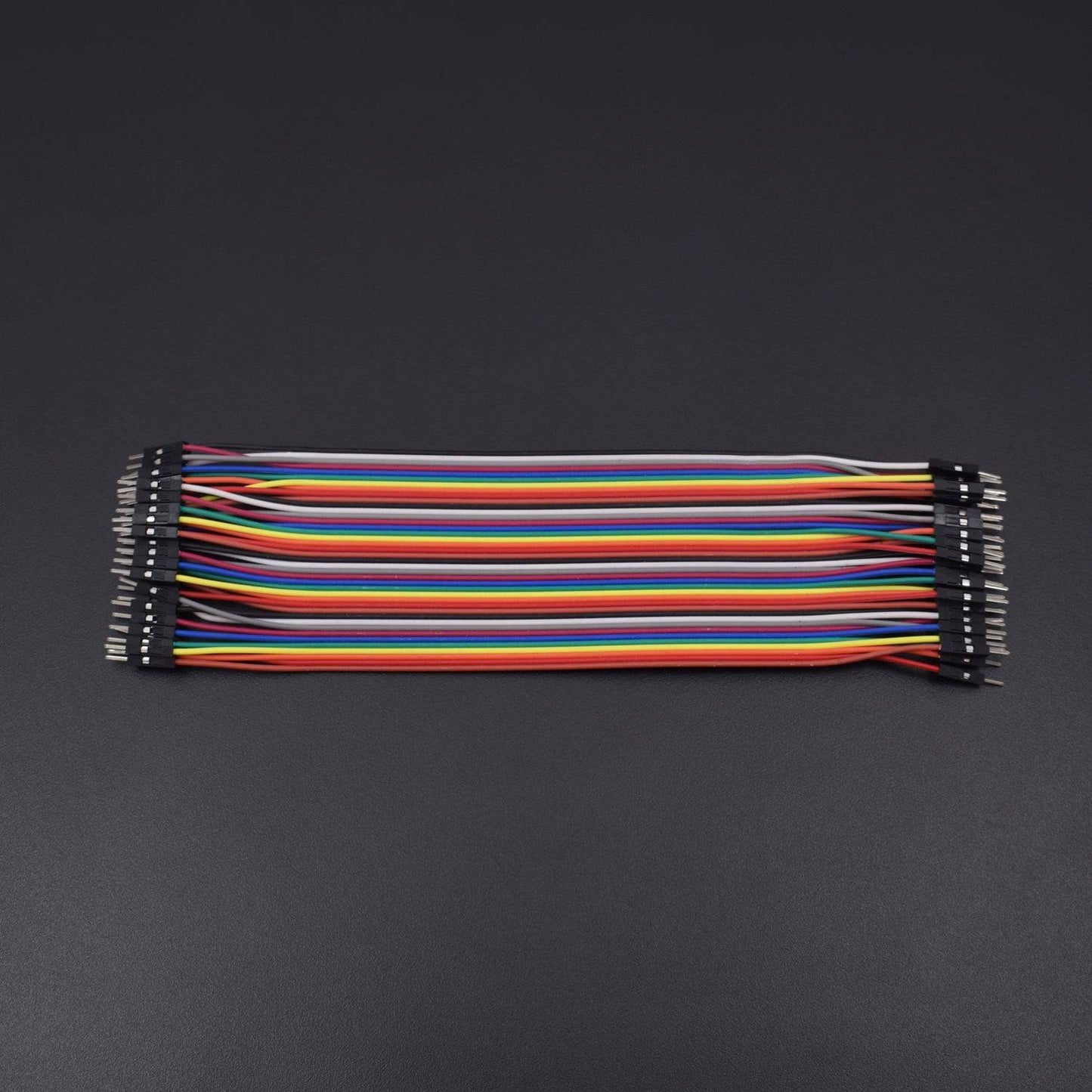
- Jumper wires(male to male) – 40 pieces
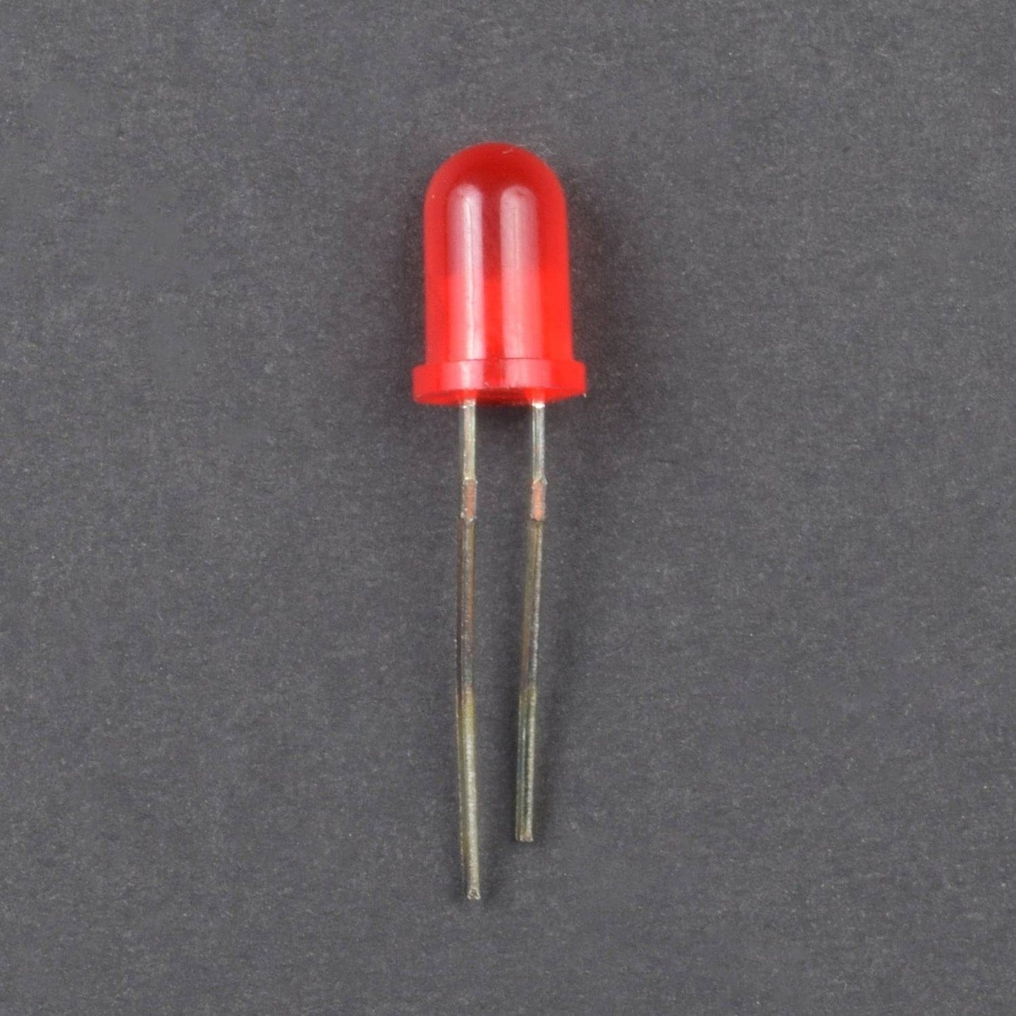
- Led - 2
HARDWARE REQUIRED
- LM 741 IC - 1
- Thermistor - 2
- Transistor BC 557 - 2
- 10K Pot - 1
- Resistor 4.7K-2, 47ohm-2
- 5V DC Fan - 1
- Battery 9V with snapper- 1
- Breadboard 840 POINTS - 1
- Single stand wire 2 meter – 1
- Jumper wires(male to male) – 40 pieces
- Led - 2
SPECIFICATIONS
Power Supply - 9v (from 9V battery)
PIN DESCRIPTION
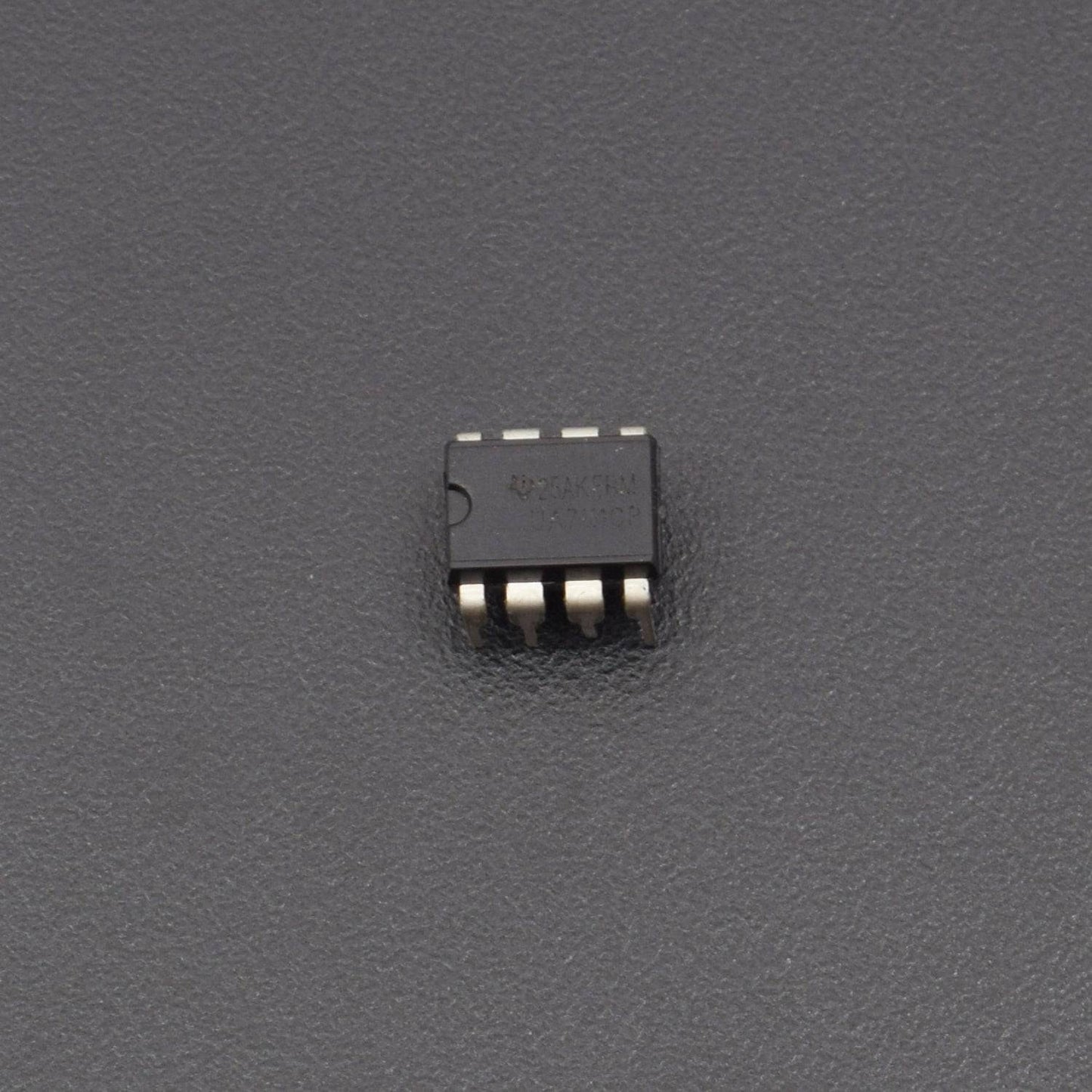
LM741 IC

A LM741 is a 8-pinop amp, meaning it has 8 pins all having their different functions.
Below is the pinout diagram of a LM741Op amp chip:
- Pin 1: Offset Null- This is the pin where we add voltage to if we want to eliminate the offset voltage. This is if we want to completely balance the input voltages. More on this at offset terminals
- Pin 2: Inverting Input- This is where the positive part of the input signal that we want to amplify goes if we want our amplified signal inverted. If we don't want it inverted, we place the positive part of the signal into the Non-inverting terminal and place the negative or ground part of our signal here.
- Pin 3: Non-inverting Input- This is where the positive part of the input signal that we want amplified goes if we want our signal non-inverted.
- Pin 4: V-- The LM741 Op amp is a dual power supply op amp, meaning it must be supplied positive DC voltage and negative DC voltage. Pin 4 is where the op amp gets supplied with negative DC voltage.
- Pin 5: Offset Null- This is the pin where we add voltage to if we want to eliminate the offset voltage. This is if we want to completely balance the input voltages. More on this at offset terminals
- Pin 6: Output- This is the terminal where the output, the amplified signal, comes out of. Whatever output the amplifier will drive gets connected to this terminal.
- Pin 7: V+- This is the terminal which receives the positive DC voltage.
- Pin 8: NC- This pin stands for Not Connected. It is not used for anything and should be left open.
741 features
- large input voltage range
- no latch-up
- high gain
- short-circuit protection
- no frequency compensation required
- same pin configuration as UA709
741 usage
- summing amplifier
- voltage follower
- integrator
- active filter
- function generator
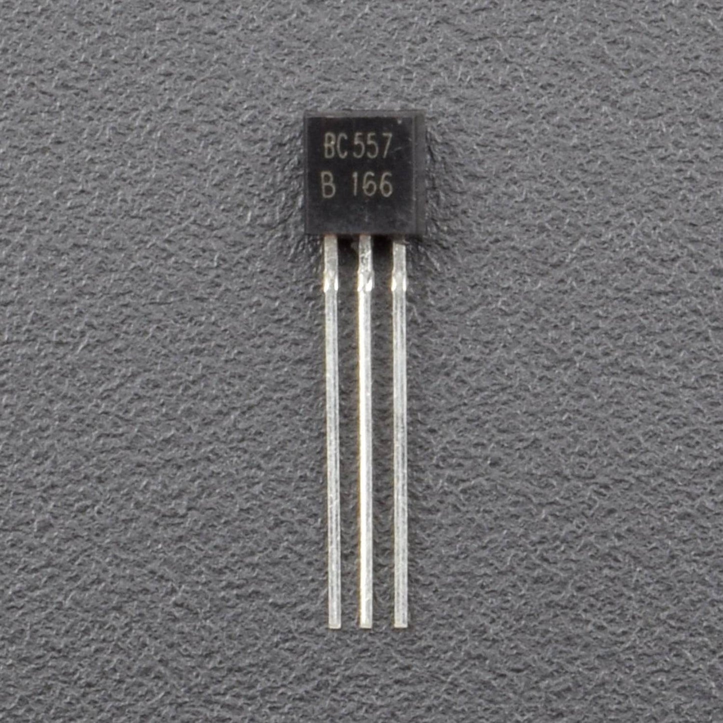
BC557 TRANSISTOR

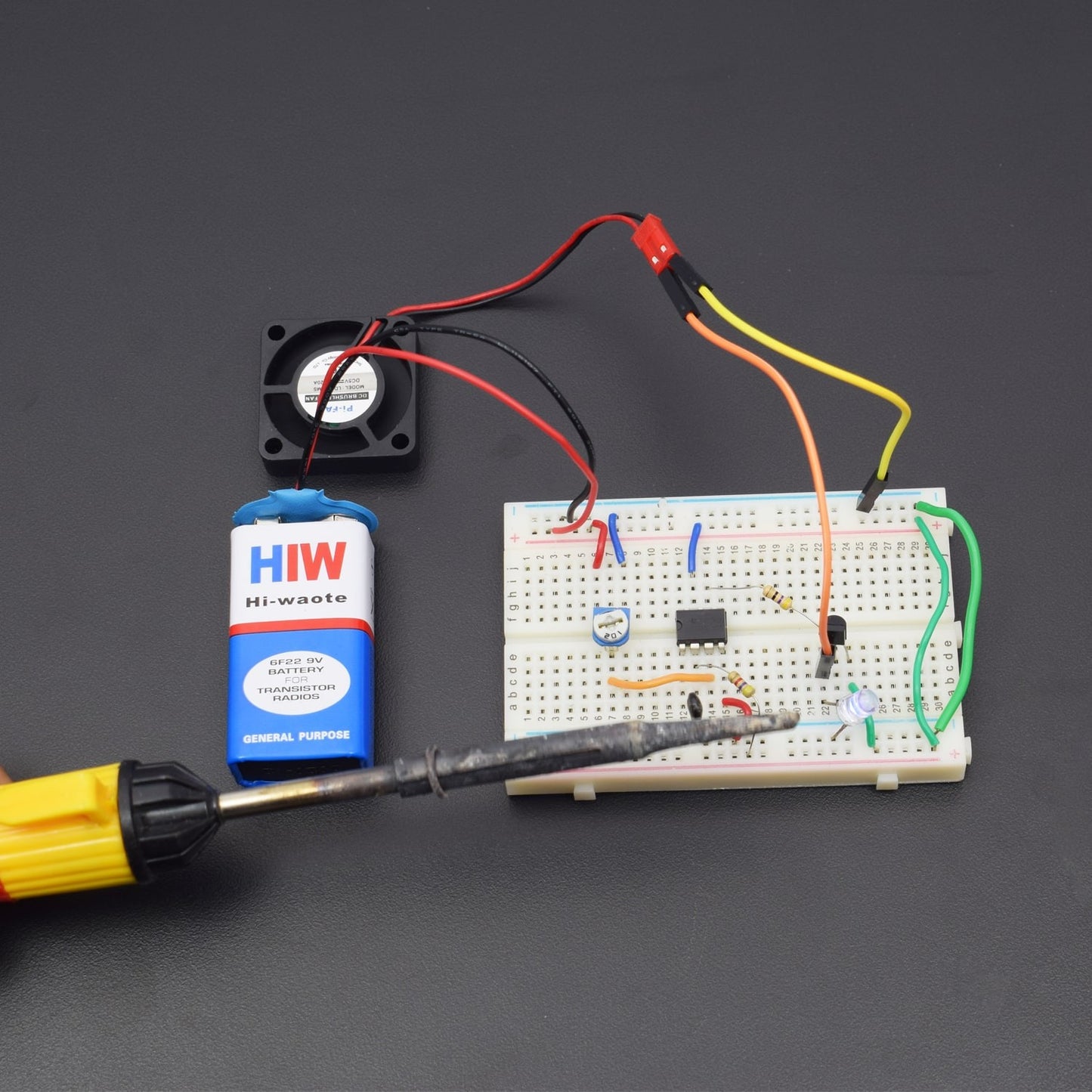
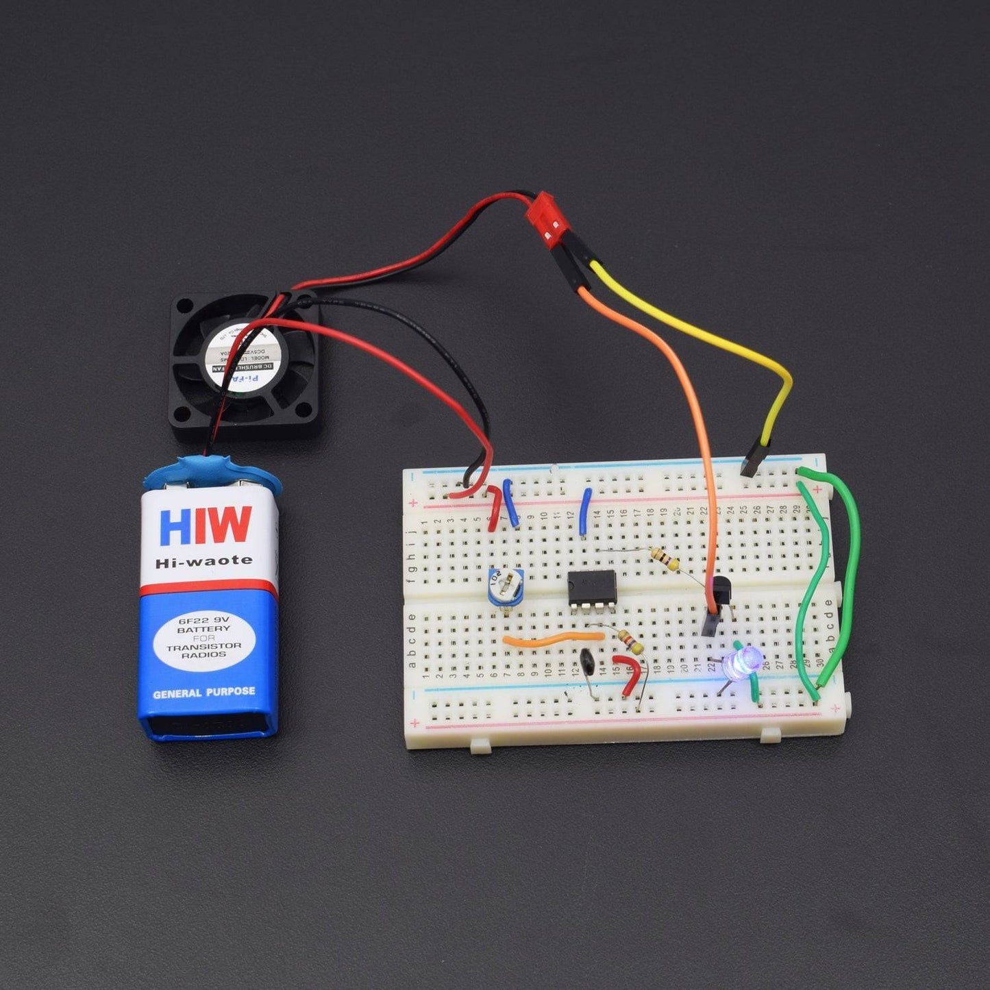
CIRCUIT DESCRIPTION


- LM 741 IC connected to the breadboard
- LM 741 IC Pin No. 3 connected to the 10K Pot Middle leg and 10K Pot 1st leg(left) connected to the positive supply and 10K Pot 2nd leg(right) is GND.
- LM 741 IC Pin No. 4 is GND and Pin No. 7 connected to the positive supply.
- LM 741 IC Pin No. 2 to connected Thermistor and thermistor 2nd leg is GND.
- LM 741 IC Pin No. 2 to connected 4.7K Resistor and Resistor 2nd leg connected to the positive supply.
- LM 741 IC Pin No. 6 connected to the 47K Resistor and Resistor 2nd leg connected to the BC 557 Transistor Middle leg.
- Transistor BC 557 1st leg to connected 5V DC Fan and 5v DC Fan 2nd leg is GND.
- Transistor’S 2nd leg connected to positive supply.
- Breadboard connection positive to positive and negative to negative
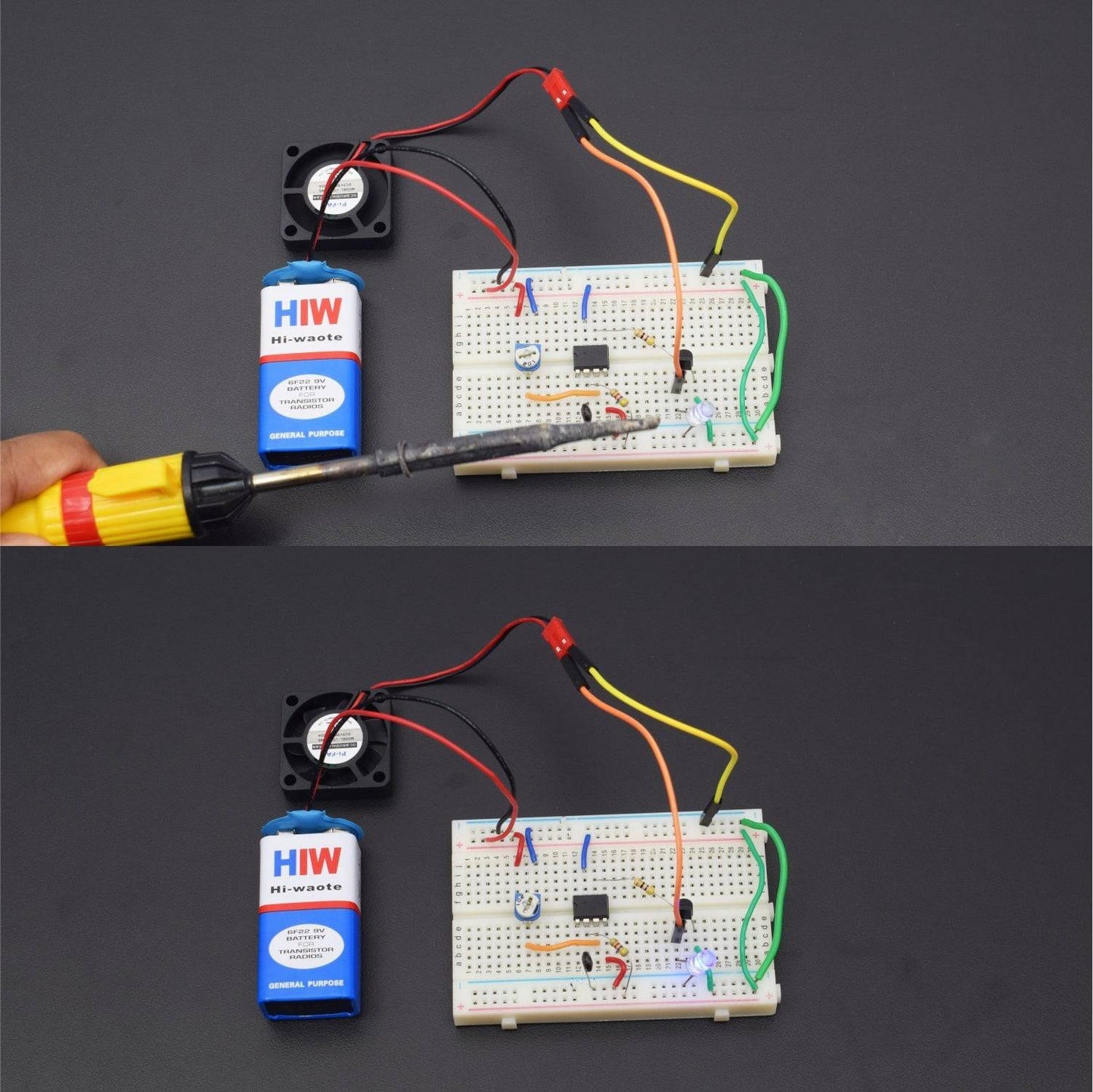
WORKING
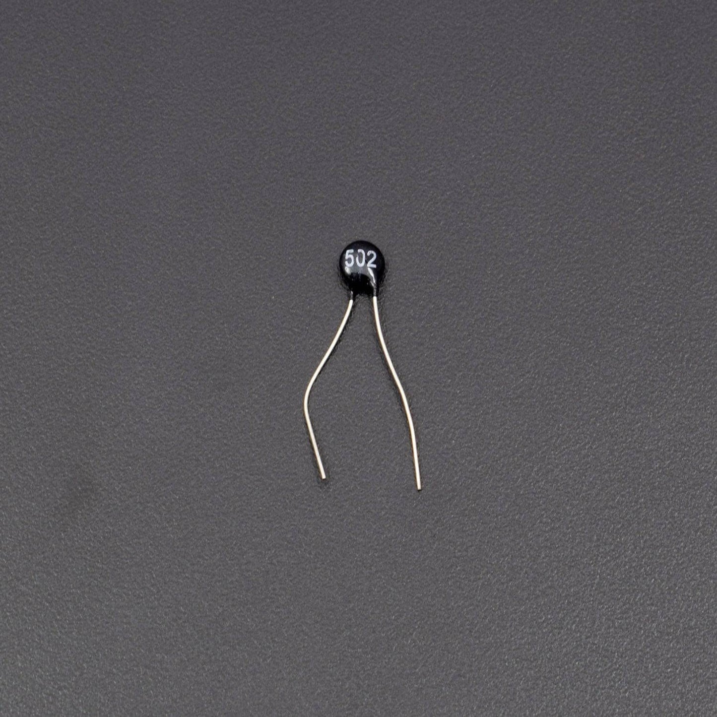
THERMISTOR
The key component of this temperature controlled fan circuit is Thermistor, which has been used to detect the rise in temperature. Thermistor is temperature sensitive resistor, whose resistance changes according to the temperature. There are two types of thermistor NTC (Negative Temperature Co-efficient) and PTC (Positive Temperature Co-efficient), we are using a NTC type thermistor. NTC thermistor is a resistor whose resistance decreases as rise in temperature while in PTC it will increase the resistance as rise in temperature.
LM741 IC
An operational amplifier is a DC-coupled high gain electronic voltage amplifier. It’s a small chip having 8 pins. An operational amplifier IC is used as a comparator which compares the two signal, the inverting and non-inverting signal. In Op-amp IC 741 PIN2 is an inverting input terminal and PIN3 is non-inverting input terminal. The output pin of this IC is PIN6. The main function of this IC is to do mathematical operation in various circuits.
Op-amp basically has Voltage Comparator inside, which has two inputs, one is inverting input and second is non-inverting input. When voltage at non-inverting input (+) is higher than the voltage at inverting input (-), then the output of comparator is high. And if the voltage of inverting input (-) is Higher than non-inverting end (+), thenoutput is LOW. Op-amps have large gain and usually used as Voltage Amplifier. The application of this IC mainly includes an adder, subtractor, voltage follower, integrator and differentiator. The output of the operational amplifier is the product of the gain and the input voltage.
CIRCUIT WORKING
It works on the principle of thermistor. In this circuit, PIN 3 (non-inverting terminal of op amp 741) is connected with the potentiometer and PIN 2 (inverting terminal) is connected in between of R2 and RT1 (thermistor) which is making a voltage divider circuit. Initially, in the normal condition the output of the op amp is LOW as the voltage at non-inverting input is lesser than inverting input which makes the NPN transistor remains in off condition. The transistor remains in OFF condition because there is no voltage applied to its base and we need some voltage at its base to make the NPN transistor conduct. Here we have used NPN transistor BC557.
Non when the temperature is increased, the resistance of Thermistor deceases and the voltage at non-inverting terminal of op-amp becomes higher than the inverting terminal, so the op amp output PIN 6 will become HIGH and transistor will be ON (because when the output of op amp is HIGH the voltage will flow through the collector to emitter). Now this conduction of NPN transistor allows the Fan to start. As the thermistor return to the normal condition the fan will automatically turn OFF.