

vendor-unknown
Make a Shadow sensor circuit using lm 741 IC - KT948
Make a Shadow sensor circuit using lm 741 IC - KT948
SKU:KT948
999 in stock
Couldn't load pickup availability
- For Bulk Order Click Here
- Need Customer Support?
- Free Delivery Above 999/-
Note: In case you receive a damaged or faulty product, please return it in the original box with all foam and packaging. Returns will not be accepted if further damage occurs due to improper packing.
If you order a product that is currently in Preorder, and the price of that item increases in the future, you will be required to pay the difference in price.
For refund/return/replacement, call us at +91 95995 94520 or email us at support@rees52.com
Delivery Time
Delivery Time
- Delivery time with the Express Shipping option is 2-3 working days, and with the Standard Shipping option is 5-6 working days. It varies based on location, reliant on courier services.
- Delivery time if the order item is on Preorder Status is 15-20 working days.
COD (Cash on Delivery)
COD (Cash on Delivery)
- For COD you have to pay extra charges of Rs 350/- before the shipment. (We will share the company QR Code, UPI ID or Account details for the same)
KIT INCLUDES
- LM 741 IC – 1
- LED - 1
- LDR - 2
- Transistor BC547 - 1
- Resistor 10K- 3, 1K - 2
- Capacitor 100nF(104) - 2
- Diode 1N4007 - 2
- Push Button - 1
- Buzzer B-10 - 1
- Single Stand Wire 2m - 1
- 400 pt Breadboard- 1
- 9v Battery - 1
- Battery Snapper - 1
HARDWARE REQUIRED
- LM 741 IC – 1
- LED - 1
- LDR - 2
- Transistor BC547 - 1
- Resistor 10K- 3, 1K - 2
- Capacitor 100nF(104) - 2
- Diode 1N4007 - 2
- Push Button - 1
- Buzzer B-10 - 1
- Single Stand Wire 2m - 1
- 400 pt Breadboard- 1
- 9v Battery - 1
- Battery Snapper - 1
SPECIFICATIONS
Power Supply - 9v (from 9v battery)
PIN DESCRIPTION
LM741 IC


A LM741 is a 8-pinop amp, meaning it has 8 pins all having their different functions.
Below is the pinout diagram of a LM741Op amp chip:
Pin 1: Offset Null- This is the pin where we add voltage to if we want to eliminate the offset voltage. This is if we want to completely balance the input voltages. More on this at offset termina
Pin 2: Inverting Input- This is where the positive part of the input signal that we want to amplify goes if we want our amplified signal inverted. If we don't want it inverted, we place the positive part of the signal into the Non-inverting terminal and place the negative or ground part of our signal here.
Pin 3: Non-inverting Input- This is where the positive part of the input signal that we want amplified goes if we want our signal non-inverted.
Pin 4: V-- The LM741 Op amp is a dual power supply op amp, meaning it must be supplied positive DC voltage and negative DC voltage. Pin 4 is where the op amp gets supplied with negative DC voltage
Pin 5: Offset Null- This is the pin where we add voltage to if we want to eliminate the offset voltage. This is if we want to completely balance the input voltages. More on this at offset terminals
Pin 6: Output- This is the terminal where the output, the amplified signal, comes out of. Whatever output the amplifier will drive gets connected to this terminal.
Pin 7: V+- This is the terminal which receives the positive DC voltage.
Pin 8: NC- This pin stands for Not Connected. It is not used for anything and should be left open.
741 features
- large input voltage range
- no latch-up
- high gain
- short-circuit protection
- no frequency compensation required
- same pin configuration as UA709
741 usage
- summing amplifier
- voltage follower
- integrator
- active filter
- function generator
BC547 TRANSISTOR


led


Capacitor


Push button


Diode


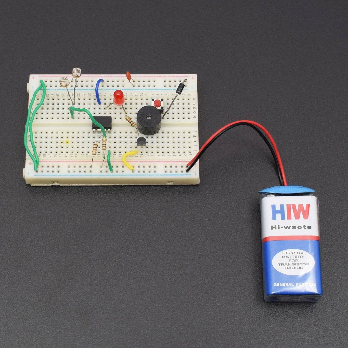
CIRCUIT DESCRIPTION
Schematic diagram


Connections


- LM 741 IC connected to the Breadboard.
- Diode 1N4007 positive leg connected to the positive supply and negative leg connected to the Push Button 1st leg.
- Push Button 2nd leg to connected Buzzer positive leg and Buzzer negative leg connected to the BC547 Transistor leg 2nd(C-right).
- Transistor BC547 Middle leg to connected 1K Resistor and Resistor 2nd leg connected to the LED negative leg , LED positive leg connected to the LM 741 IC Pin No. 6.
- Transistor BC547 1st leg(E-left) is GND.
- Push Button 2nd leg to connected 100nF(104) capacitor and capacitor 2nd leg is GND.
- Push Button 2nd leg to connected LDR 1st leg and LDR 2nd leg connected to the LM 741 IC Pin No. 3 OR Pin No. 3 to connected another LDR leg 1st and LDR 2nd leg is GND.
- LM 741 IC Pin No. 4 is GND and Pin No. 2 to connected 10K Resistor and Resistor 2nd leG is GND.
- LM 741 IC Pin No. 2 to connected 10K Resistor and Resistor 2nd leg connected to the Pin No. 7 and Pin No. 7 connected to the Push Button 2nd leg.
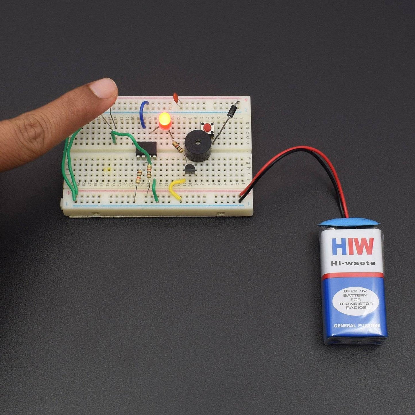
WORKING
Shadow sensors are widely used to detect the movement of a person in a confined area. Described here is a simple but improved circuit of a smart shadow sensor alarm, which can register a shadow when there is a light difference. Here two 5mm LDRs are used with the popular Op-amp LM741CN to drive an active piezo-sounder when a “valid” shadow is detected. The whole shadow sensor circuit can be powered from four 1.5V AA cells (6VDC), or similar dc supply sources.