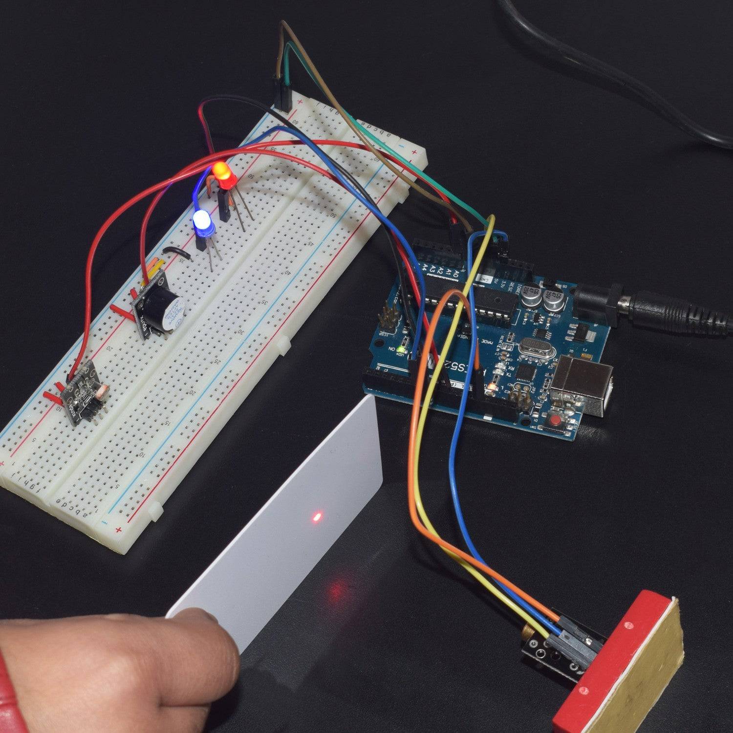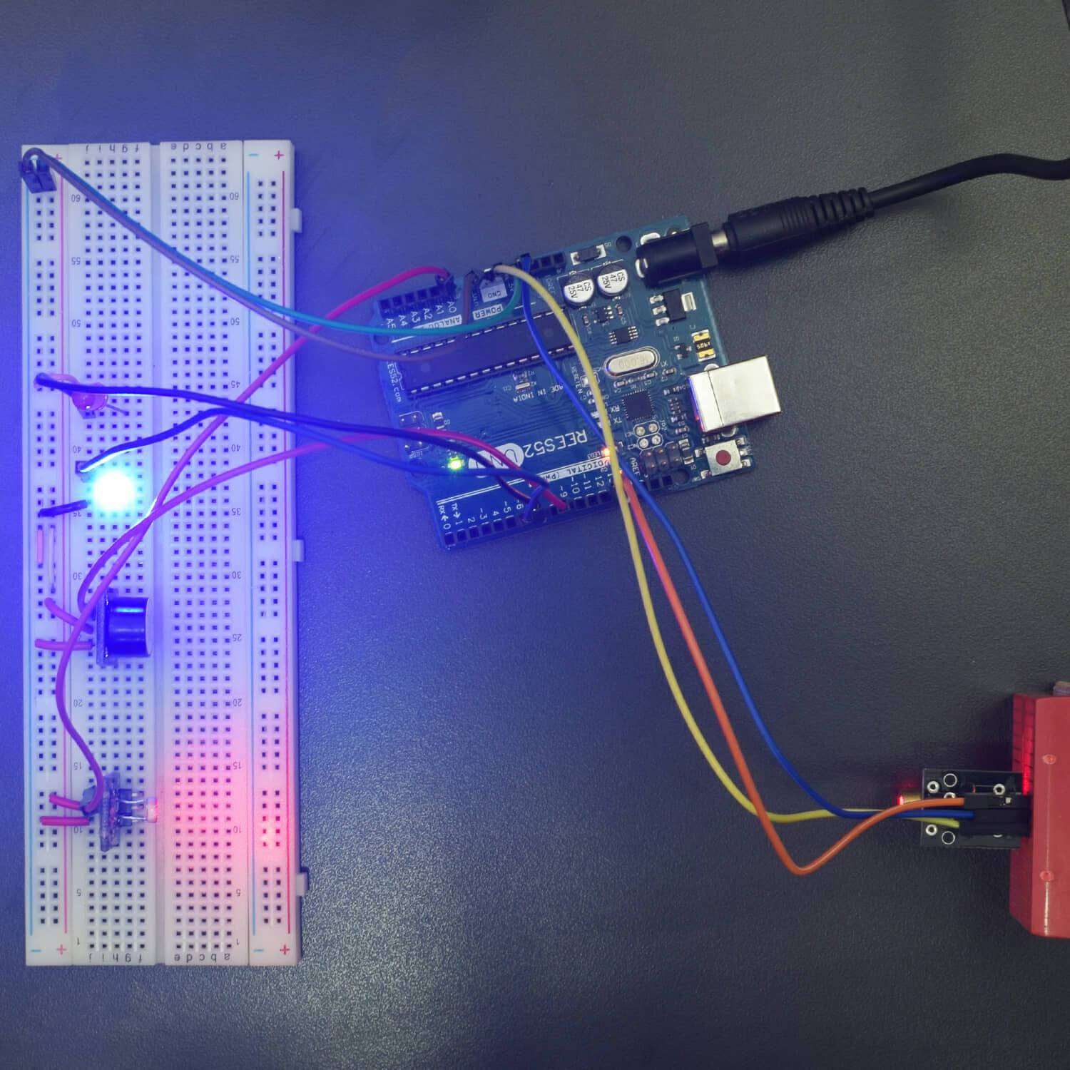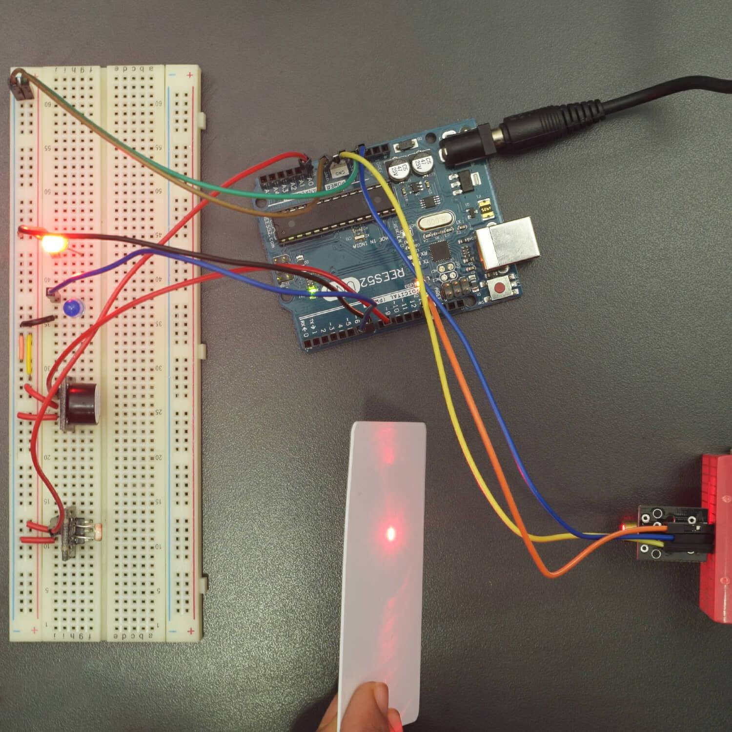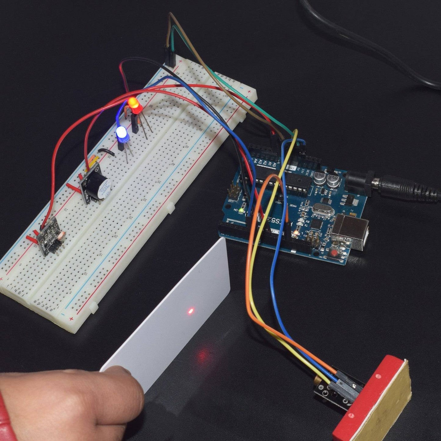

Hardware Required
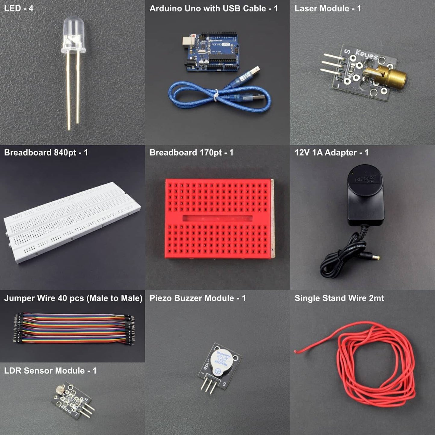
- Arduino Uno With USB Cable - 1
- Laser Module - 1
- LDR Sensor Module - 1
- Peizo Buzzer Module - 1
- LED - 4
- Bread Board 840 Point - 1
- Bread Board 170 Point - 2
- 12V 1A Adapter - 1
- Jumper Wire (male to male) - 40 pcs
- Single Stand Wire - 1
Introduction
In this project, we will make a Security System which includes Laser Module and LDR Module.
HARDWARE REQUIRED
- Arduino Uno With USB Cable - 1
- Laser Module - 1
- LDR Sensor Module - 1
- Peizo Buzzer Module - 1
- LED - 4
- Bread Board 840 Point - 1
- Bread Board 170 Point - 2
- 12V 1A Adapter - 1
- Jumper Wire (male to male) - 40 pcs
- Single Stand Wire - 1
SOFTWARE REQUIRED
Arduino IDE 1.8.5 (programmable platform for Arduino)
Click To Download :https://www.arduino.cc/en/Main/Software
SPECIFICATIONS
Laser Module
This particular sensor is used to create trip wires or optical effects. It is particularly neat because it can be directly powered from an Arduino output pin as it only draws 30 mA from the processor that has outputs rated for 40 mA.
Supply Voltage |
5 Vdc |
Current |
30 mA |
Wavelength |
650 nm |
Color |
Red |

LDR Sensor Module
An LDR is a component that has a (variable) resistance that changes with the light intensity that falls upon it. This allows them to be used in light sensing circuits.
LDR has no polarity just like a resistor. The resistance of LDR can be very easily measured by just connecting the two terminals of LDR to a Multimeter & set the Multimeter on resistance Mode. It consists of a photo resistor and a 10kΩ in-line resistor. The photo resistor’s resistance will decrease in the presence of light and increase in the absence of it. The output is analog and determines the intensity of light.
- Operating Voltage: 3.3V to 5V
- Output Type: Analog

CIRCUIT CONNECTION
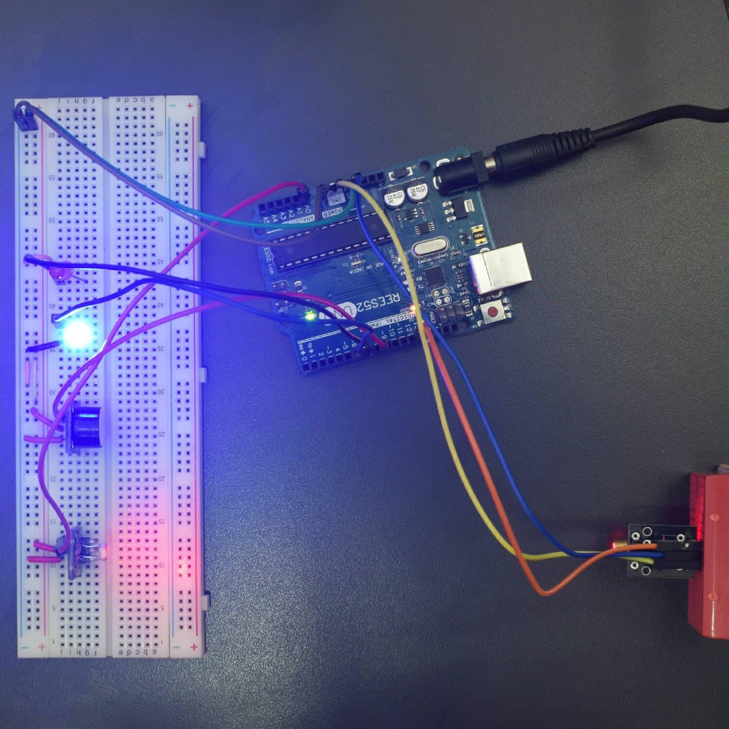
- Connect GND of Arduino Uno with Breadboard for further GND connections.
- Connect Pin 5V of Arduino Uno with Breadboard for further 5V power supply connections.
- Attach two LEDs and Buzzer on Breadboard.
- Connect negative terminals of both LEDs with GND rail of Breadboard.
- Connect negative terminal of Buzzer with GND rail of Breadboard.
- Connect positive terminal of Blue LED with Digital Pin 6 of Arduino Uno.
- Connect positive terminal of Red LED with Digital Pin 7 of Arduino Uno.
- Connect GND of LDR module with GND rail of Breadboard.
- Connect GND of Laser module with GND rail of Breadboard.
- Connect VCC of LDR module with 5V rail of Breadboard.
- Connect Pin Signal of LDR module with Analog Pin A0 of Arduino Uno.
- Connect VCC of Laser module with Pin 3.3V of Arduino Uno.
- Connect Pin Signal of Laser module with Digital Pin 13 of Arduino Uno.

CODE
https://drive.google.com/open?id=1IB-isasi7q54098aIZhE8ljHzrII7t3z
WORKING
Welcome to the Arduino Based Project which consists of LDR module and Laser module. The basic working principle of Laser Module is being described here. The natural white light is made up of all the VIBGYOR colors of the visible light spectrum, which is a broad wide band of many different frequencies. The ordinary LEDs give a light output often consisting of one color, but even that light contains electromagnetic waves, which cover a quite wide band of frequencies. The lens system focusing the light has a fixed focal length, but the focal length required to focus on various wavelengths (colors) of light is different. Therefore, each color will focus at different points, causing ‘chromatic aberration’.
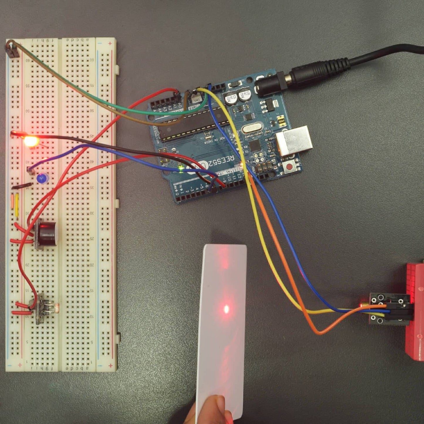
The laser diode lightcontains only a single frequency. Therefore, it can be focused by even a simple lens system to an extremely small point. There is no chromatic aberration since only one wavelength exists, also all of the energy from the light source is concentrated into a very small spot of light. LASER is an acronym for Light Amplification by the Stimulated Emission of Radiation. Here, we will use Laser module for security system and when there’s an unauthorized entry (Laser is crossed), the Red LED blinks and Buzzer beeps. If it is authorized entry (Laser is not crossed), then Blue LED blinks.


