
vendor-unknown
Make a robot car using LDR and transistor 3906 - kt888
Make a robot car using LDR and transistor 3906 - kt888
SKU:KT888
1000 in stock
Couldn't load pickup availability
- For Bulk Order Click Here
- Need Customer Support?
- Free Delivery Above 999/-
Note: In case you receive a damaged or faulty product, please return it in the original box with all foam and packaging. Returns will not be accepted if further damage occurs due to improper packing.
If you order a product that is currently in Preorder, and the price of that item increases in the future, you will be required to pay the difference in price.
For refund/return/replacement, call us at +91 95995 94520 or email us at support@rees52.com
Delivery Time
Delivery Time
- Delivery time with the Express Shipping option is 2-3 working days, and with the Standard Shipping option is 5-6 working days. It varies based on location, reliant on courier services.
- Delivery time if the order item is on Preorder Status is 15-20 working days.
COD (Cash on Delivery)
COD (Cash on Delivery)
- For COD you have to pay extra charges of Rs 350/- before the shipment. (We will share the company QR Code, UPI ID or Account details for the same)


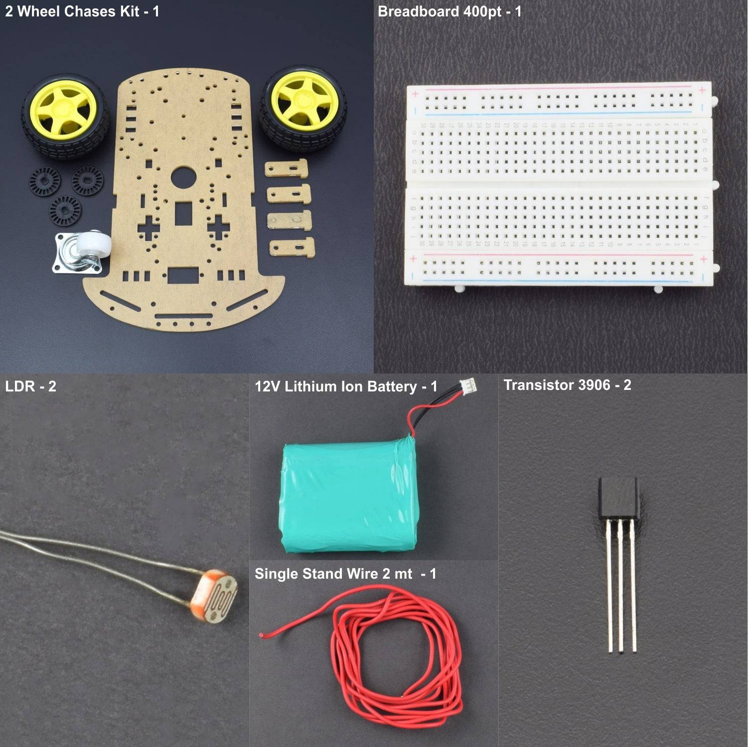
KIT INCLUDES:
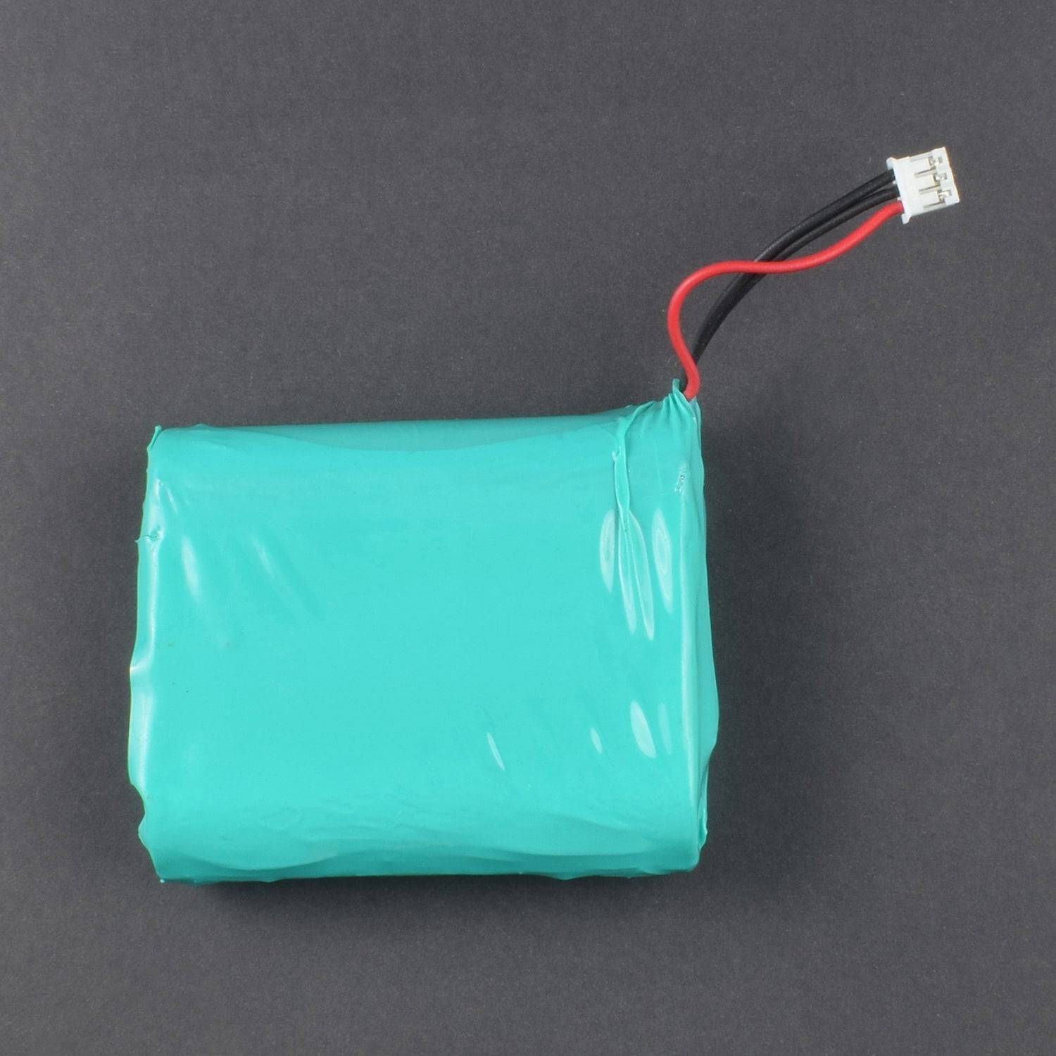
- 12V Lithium Ion Battery – 1
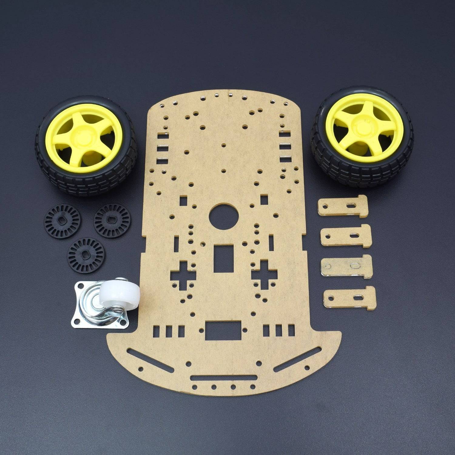
- 2 Wheel Chassis Kit- 1
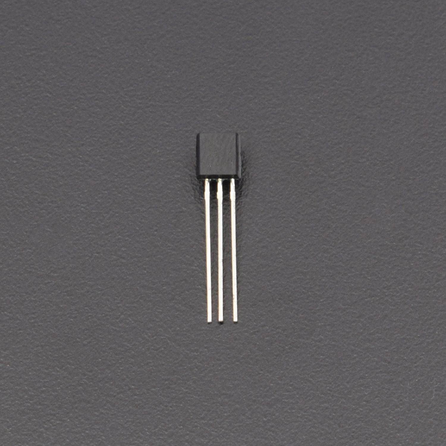
- 3906 transistor- 2
- LDR- 2
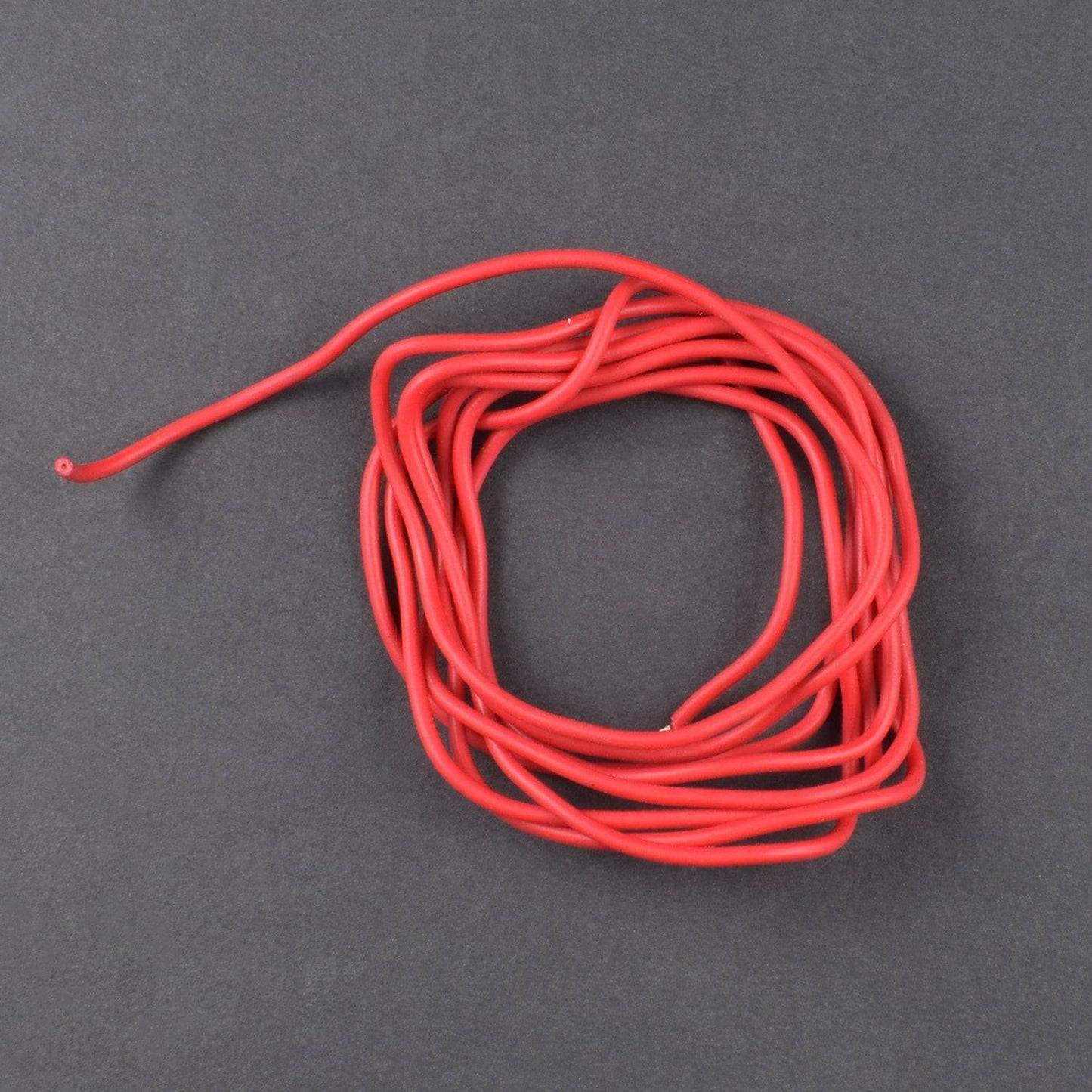
- Single Stand Wire 2mt - 1
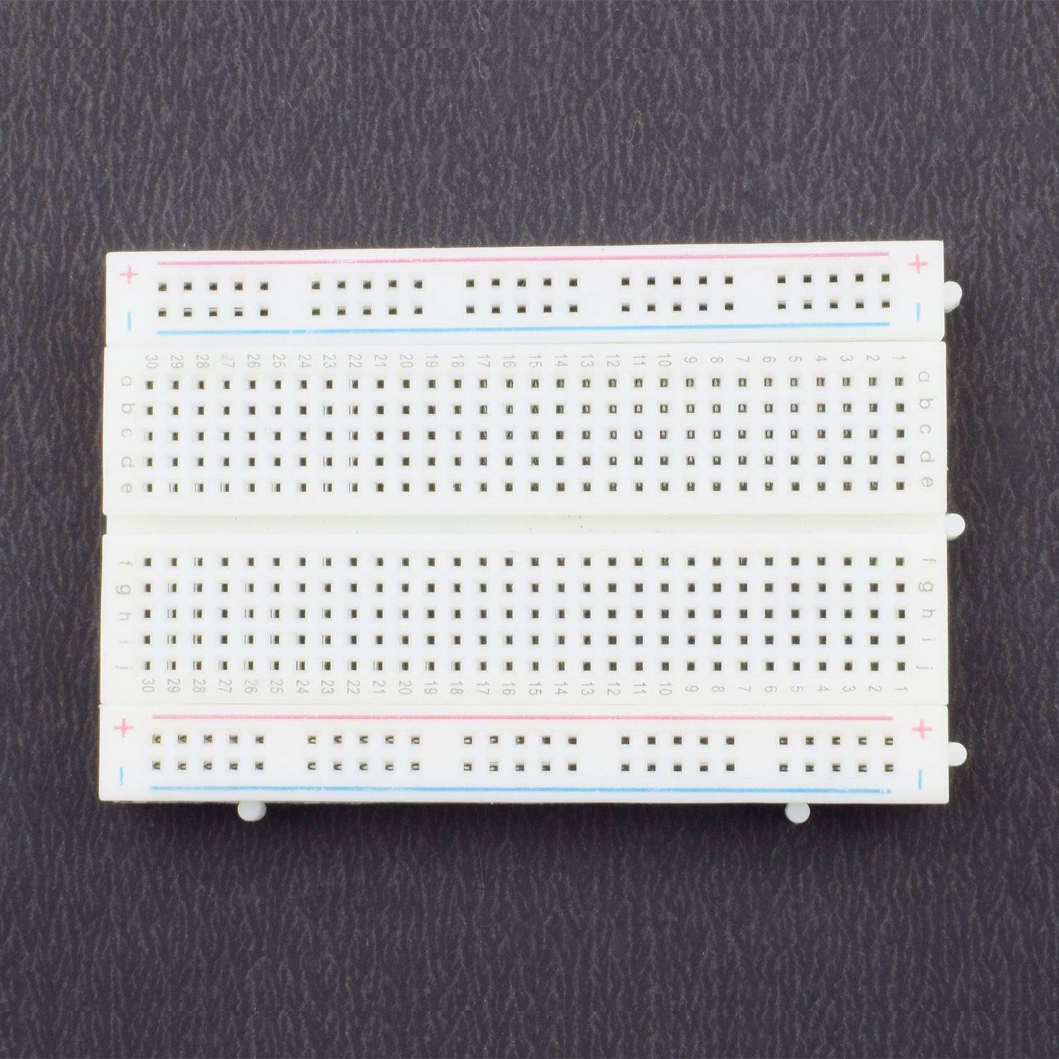
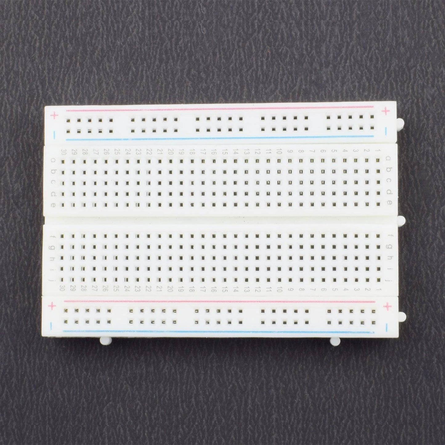
- Breadboard 400 pt - 1
HARDWARE REQUIRED
- 12V Lithium Ion Battery – 1
- 2 Wheel Chassis Kit- 1
- 3906 transistor- 2
- LDR- 2
- Single Stand Wire 2mt - 1
- Breadboard 400 pt - 1
SPECIFICATIONS
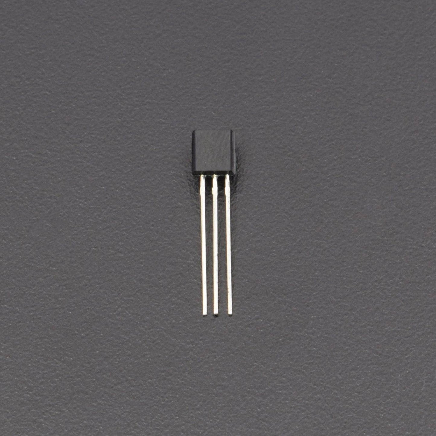
TRANSISTOR 3906
- Bi-Polar PNP Transistor
- DC Current Gain (hFE) is 300 maximum
- Continuous Collector current (IC) is 200mA
- Emitter Base Voltage (VBE) is 5V
- Base Current(IB) is 5mA maximum
- Collector Emitter Voltage (VCE) is 40V
- Collector Base Voltage (VCB) is 40V
- Available in To-92 Package
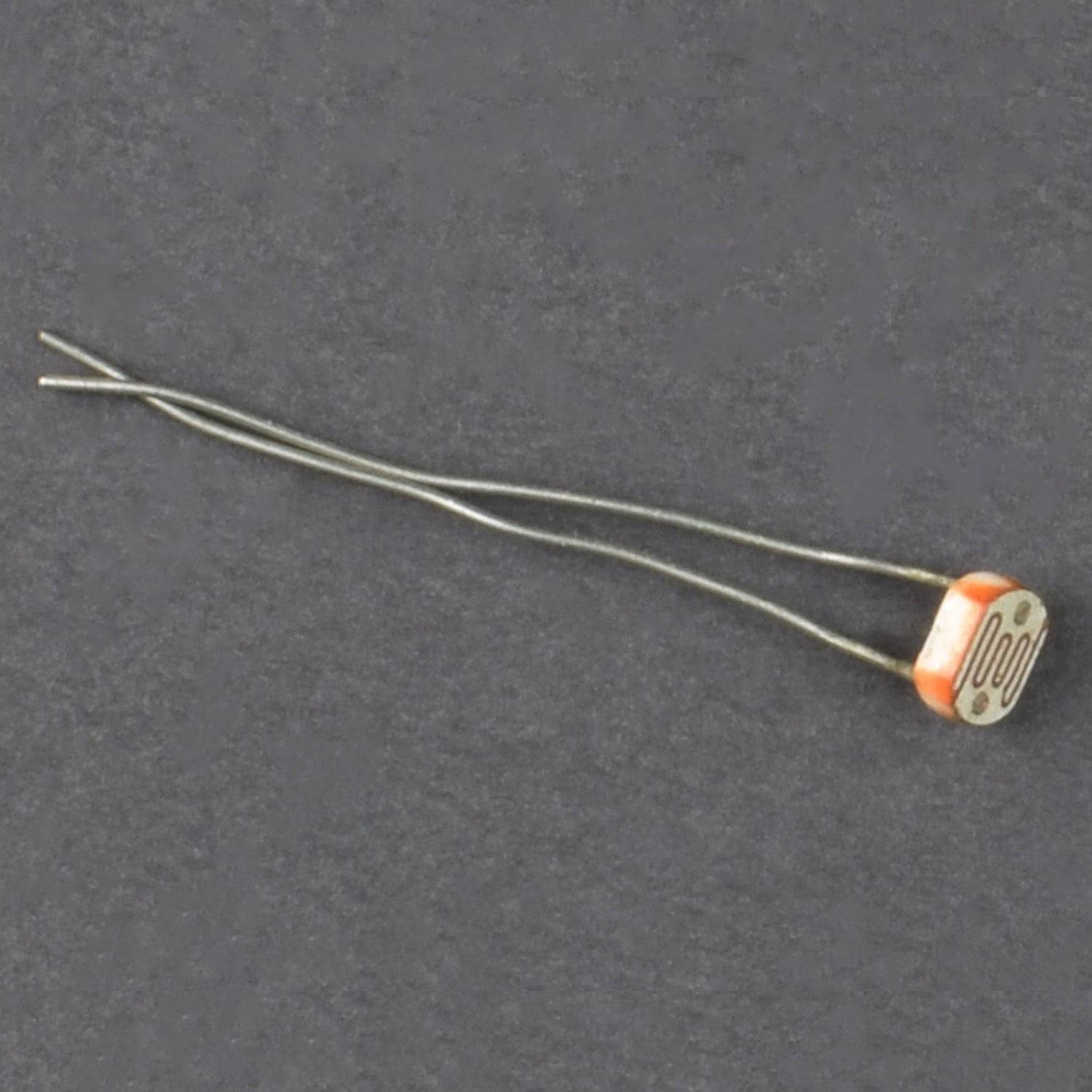
LDR (Light Dependent Resistor)
A photoresistor or light dependent resistor is a component that is sensitive to light. When light falls upon it then the resistance changes. Values of the resistance of the LDR may change over many orders of magnitude the value of the resistance falling as the level of light increases.
- Can be used to sense Light
- Easy to use on Breadboard or Perf Board
- Easy to use with Microcontrollers or even with normal Digital/Analog IC
- Small, cheap and easily available
- Available in PG5 ,PG5-MP, PG12, PG12-MP, PG20 and PG20-MP series.
PIN DESCRIPTION
TRANSISTOR 3906
Pin Number |
Pin Name |
Description |
1 |
Emitter |
Current Drains out through emitter |
2 |
Base |
Controls the biasing of transistor |
3 |
Collector |
Current flows in through the collector |

LDR (Light Dependent Resistor)
.png)
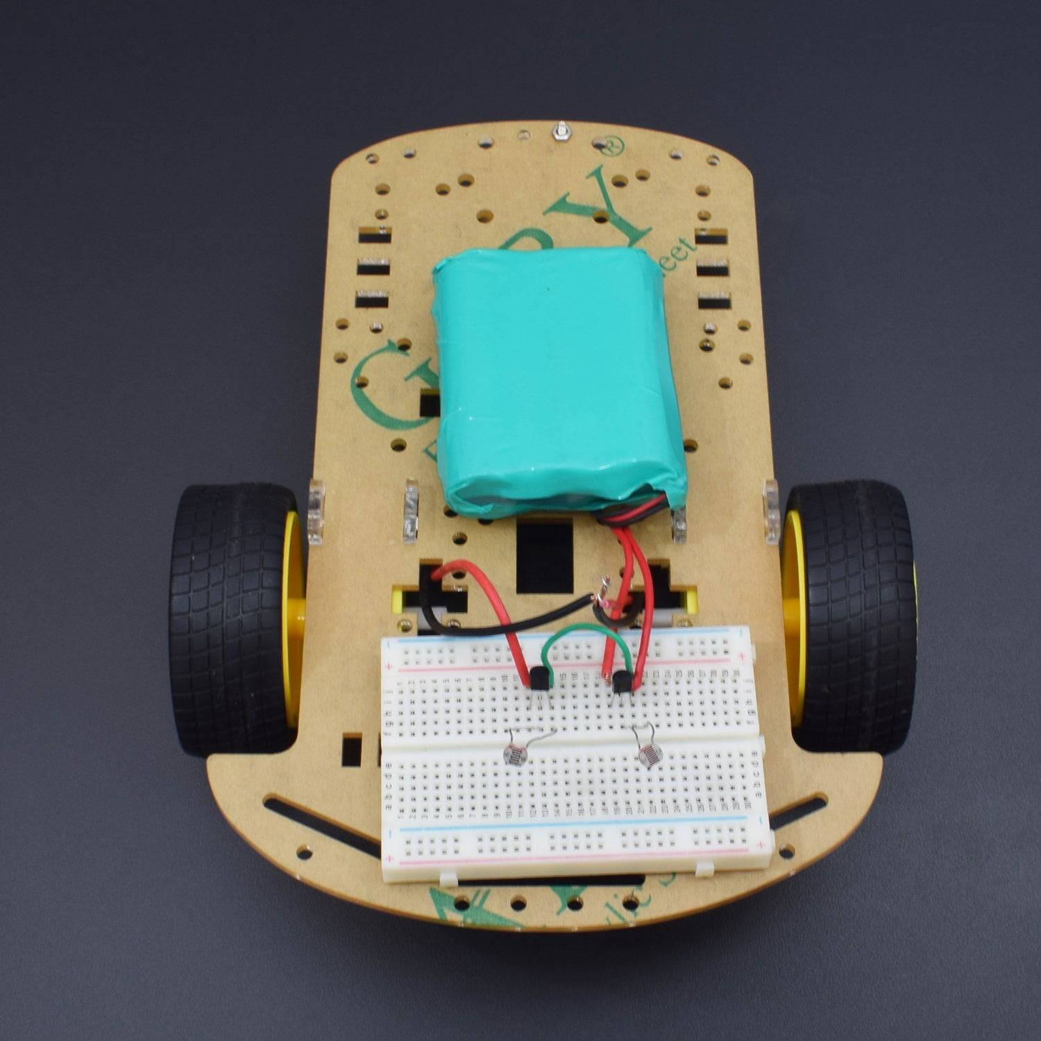
CIRCUIT CONNECTION
- First, we connect both the positive terminals of the BO motor with the positive terminal of 9V Battery (as given in image below).
- Now connect both the negative terminals of BO motor with the Emitter of 3906 Transistor (as given in image below).
- Connect both the LDR points with the Pin Base and Pin Collector of 3906 Transistor for further connection.
- Common connect both the Collector Pins of 3906 Transistor and then connect them to battery negative terminal (GND).
- Lastly, it should be made sure that all the circuit connections are made in an appropriate manner.

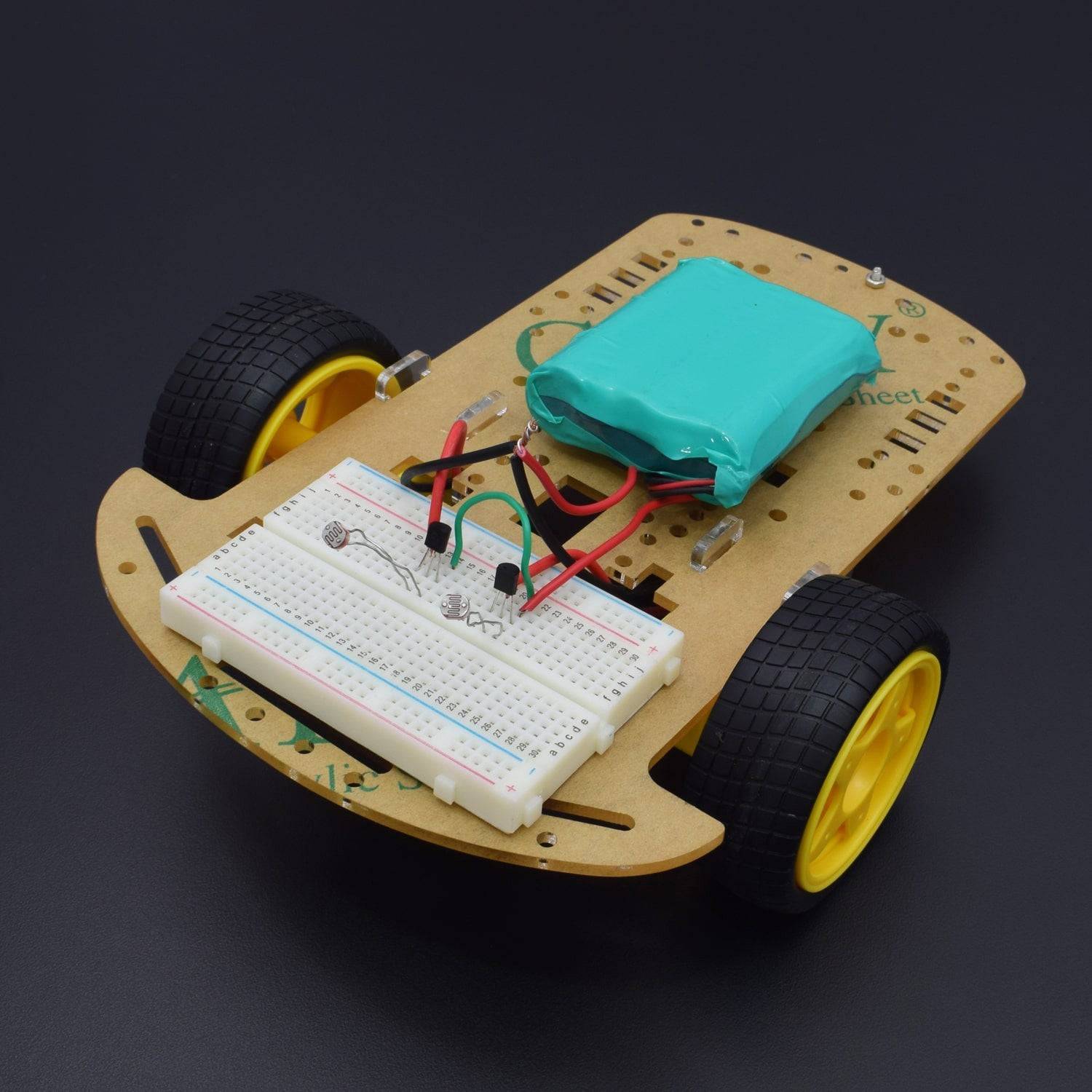
WORKING
Welcome to the Arduino Based Project LDR Controlled Smart Robot Car which consists of LDR (Light Dependent Resistor) AND 3906 Transistor. Here, the working of the robot car is being shown in which we will provide light over theLDR which changes its resistivity values and makes the motor work and it starts running. One by one you put light on the ldr the robot will start working.
Here’s the basic functionality of LDR being described. The LDR is also called a photoconductor which is basically a photocell that works on the principle of photoconductivity. The passive component is basically a resistor whose resistance value decreases when the intensity of light decreases.
This optoelectronic device is mostly used in light varying sensor circuit, and light and dark activated switching circuits.
Some of its applications include:
- Camera light meters
- Street lights
- Clock radios
- Light beam alarms
- Reflective smoke alarms
- Outdoor clocks
LDR ControlledTransistor Circuit
