


vendor-unknown
Make a Radio Car using 434 MHz RF Link Transmitter receiver kit - KT997
Make a Radio Car using 434 MHz RF Link Transmitter receiver kit - KT997
SKU:KT997
1000 in stock
Regular price
Rs. 1,399.00
Regular price
Sale price
Rs. 1,399.00
Unit price
per
Shipping calculated at checkout.
Couldn't load pickup availability
- For Bulk Order Click Here
- Need Customer Support?
- Free Delivery Above 999/-
Note: In case you receive a damaged or faulty product, please return it in the original box with all foam and packaging. Returns will not be accepted if further damage occurs due to improper packing.
If you order a product that is currently in Preorder, and the price of that item increases in the future, you will be required to pay the difference in price.
For refund/return/replacement, call us at +91 95995 94520 or email us at support@rees52.com
Delivery Time
Delivery Time
- Delivery time with the Express Shipping option is 2-3 working days, and with the Standard Shipping option is 5-6 working days. It varies based on location, reliant on courier services.
- Delivery time if the order item is on Preorder Status is 15-20 working days.
COD (Cash on Delivery)
COD (Cash on Delivery)
- For COD you have to pay extra charges of Rs 350/- before the shipment. (We will share the company QR Code, UPI ID or Account details for the same)


434 MHz RF Link Transmitter receiver kit
- Frequency 434 MHz
- Transmitter supply voltage: 3~12V.
- Receiver Supply voltage: 5V
- Receiver IF frequency: 500 kHz
- Receiver Sensitivity: -105dBm
- Receiver Supply current: 2.3mA
- Output power: 4~16dBm
- Operating Voltage: 5 Volts
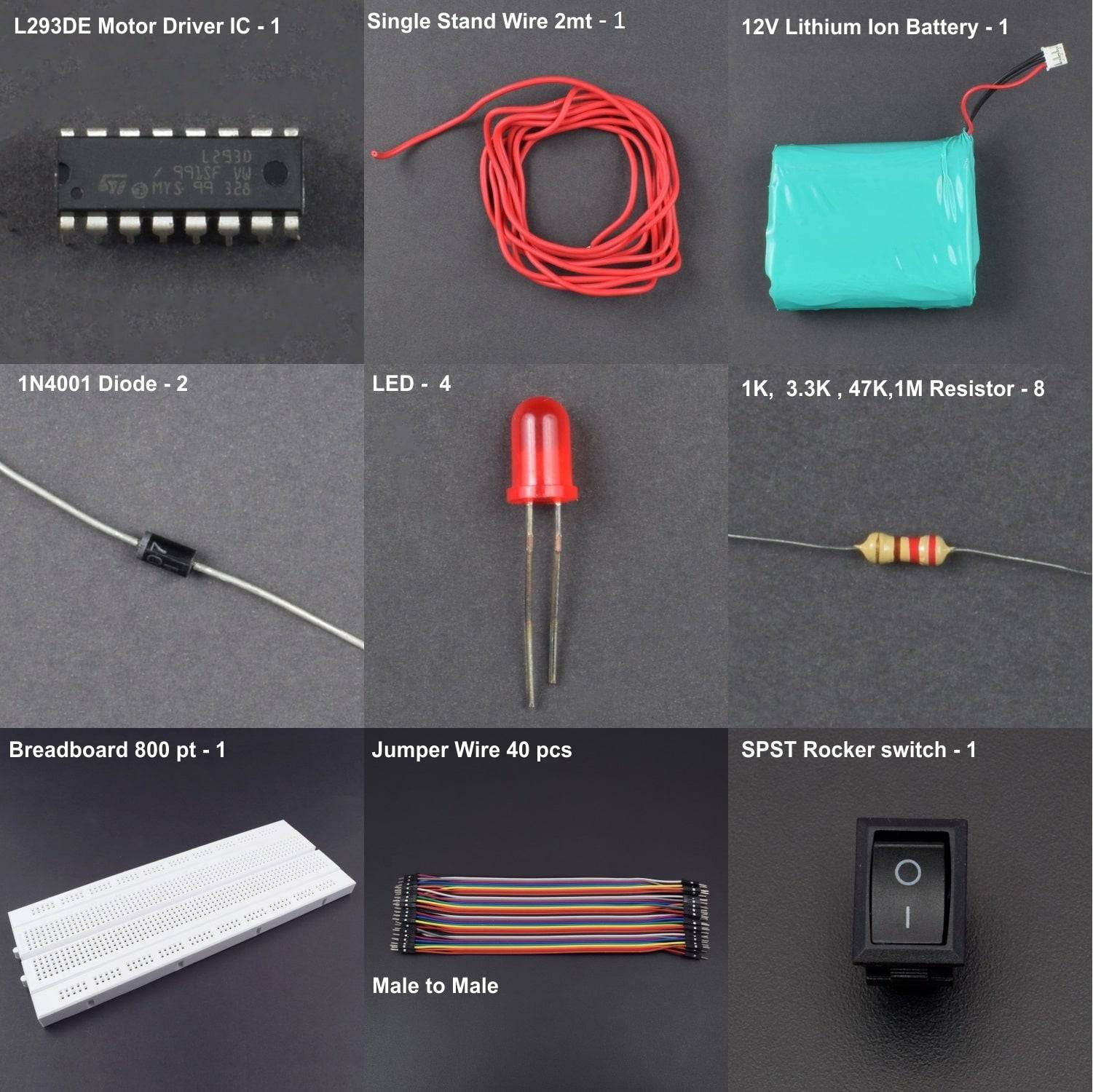
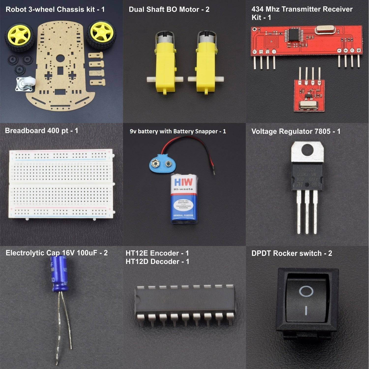
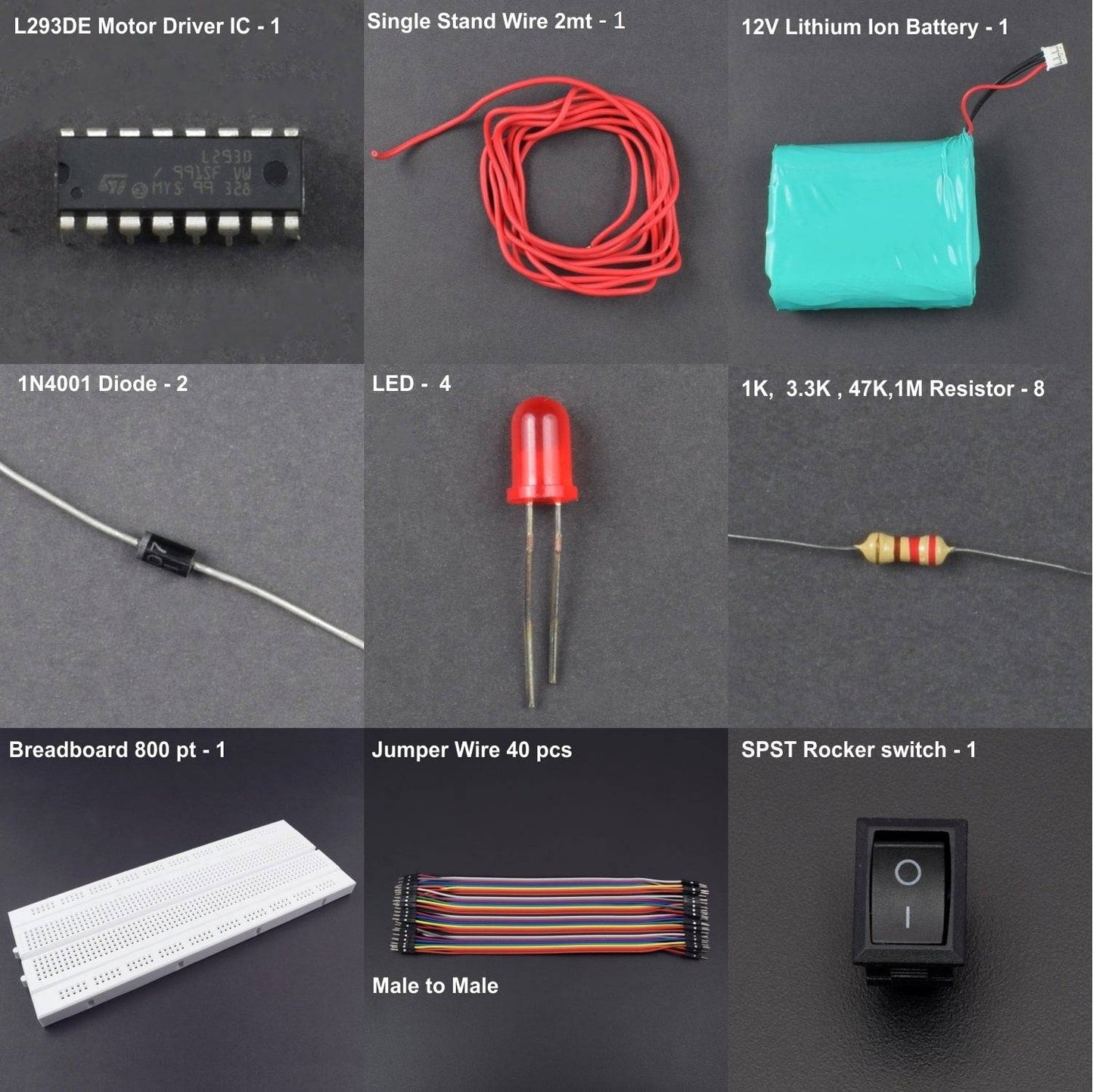
HARDWARE REQUIRED
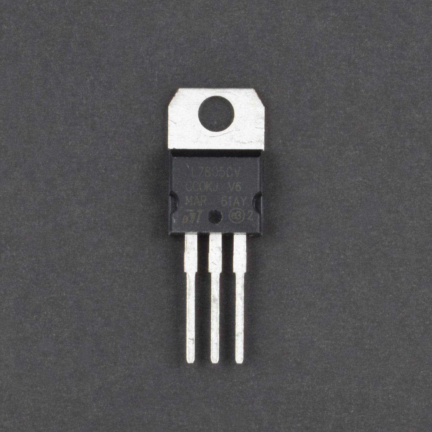
- 1x Voltage Regulator 7805
- 2x 1N4001 Diode
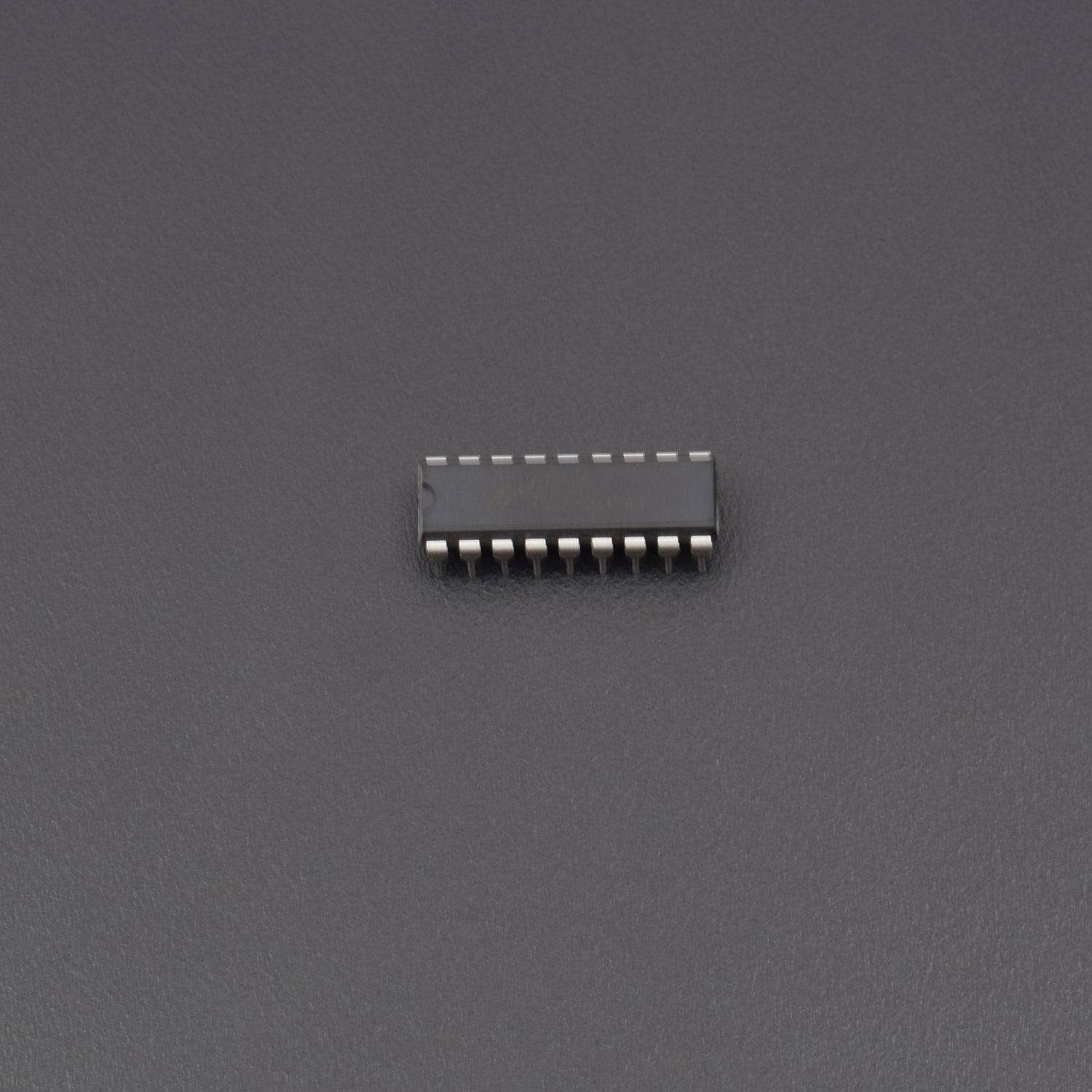
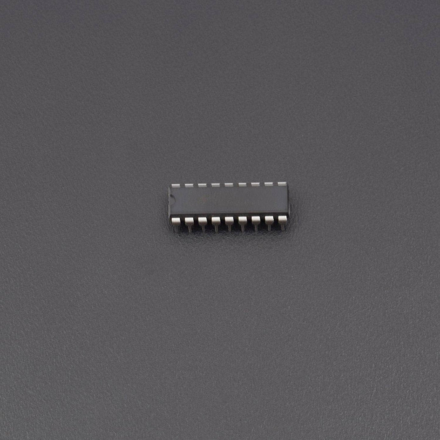
- 1x HT12E Encoder
- 1x HT12D Decoder
- 1 x 434MHz RF Link Transmitter Receiver kit
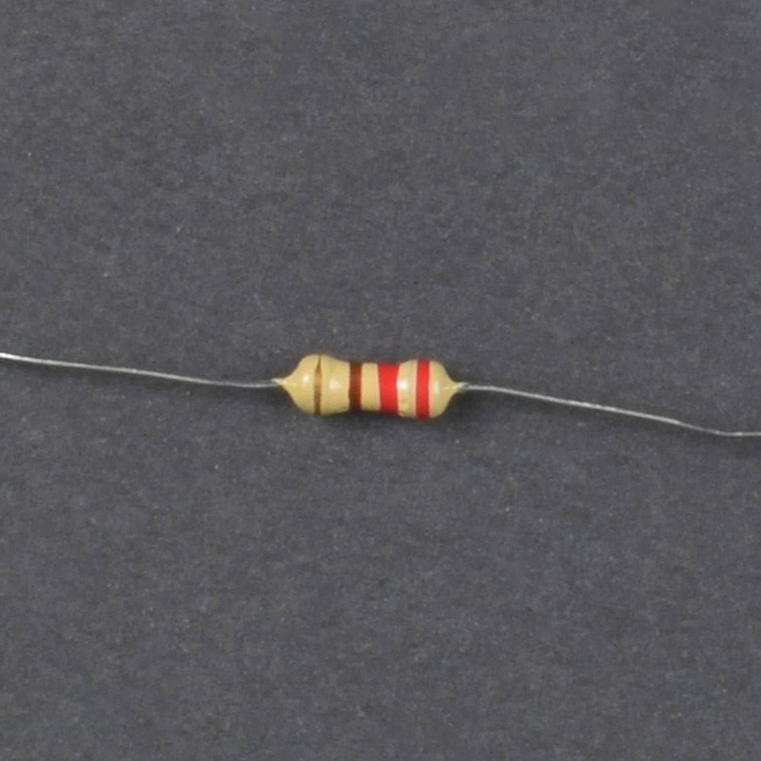
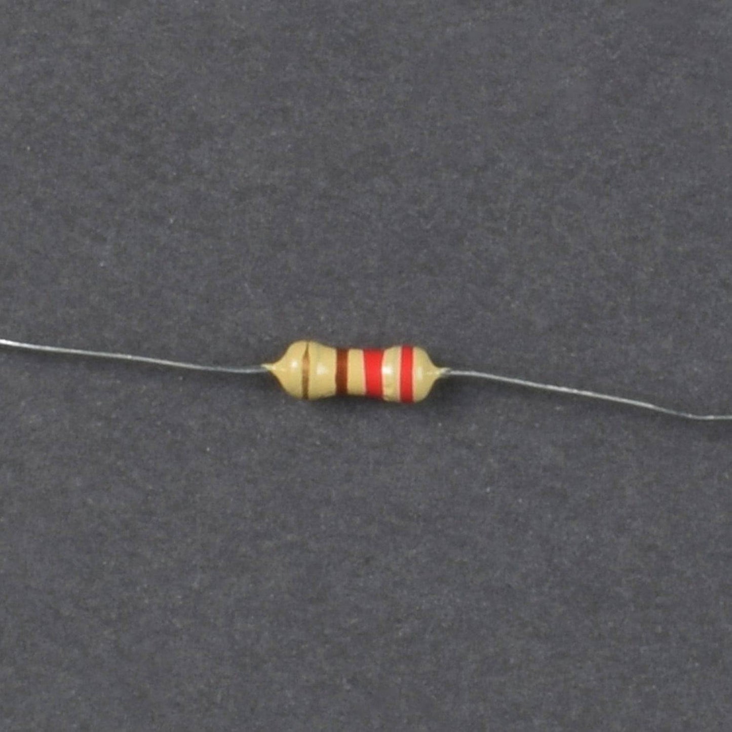
- 2x 1K Resistor
- 2x 3.3K Resistor
- 2x 47K Resistor
- 2x 1M Resistor
- 1X L293D Motor Driver IC
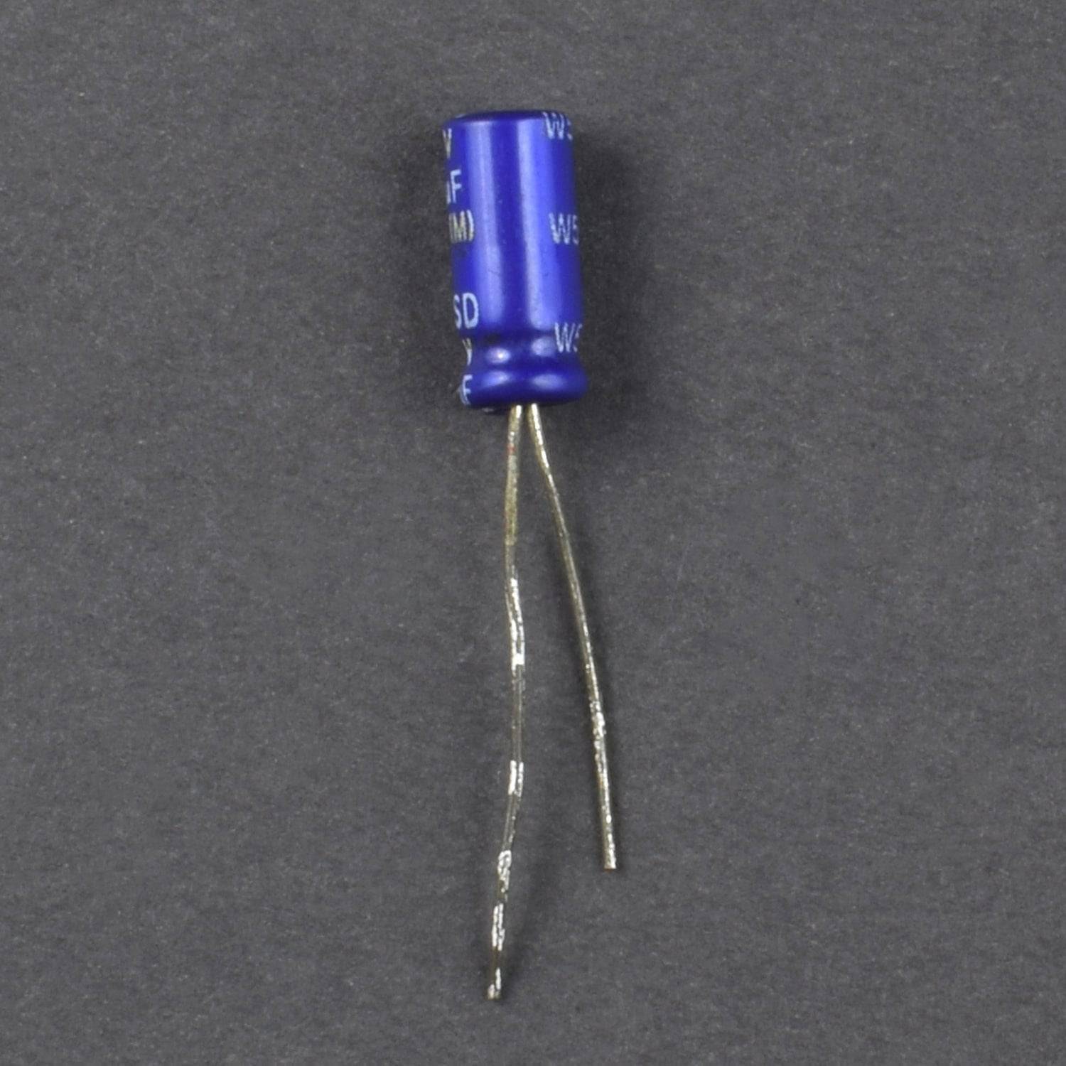
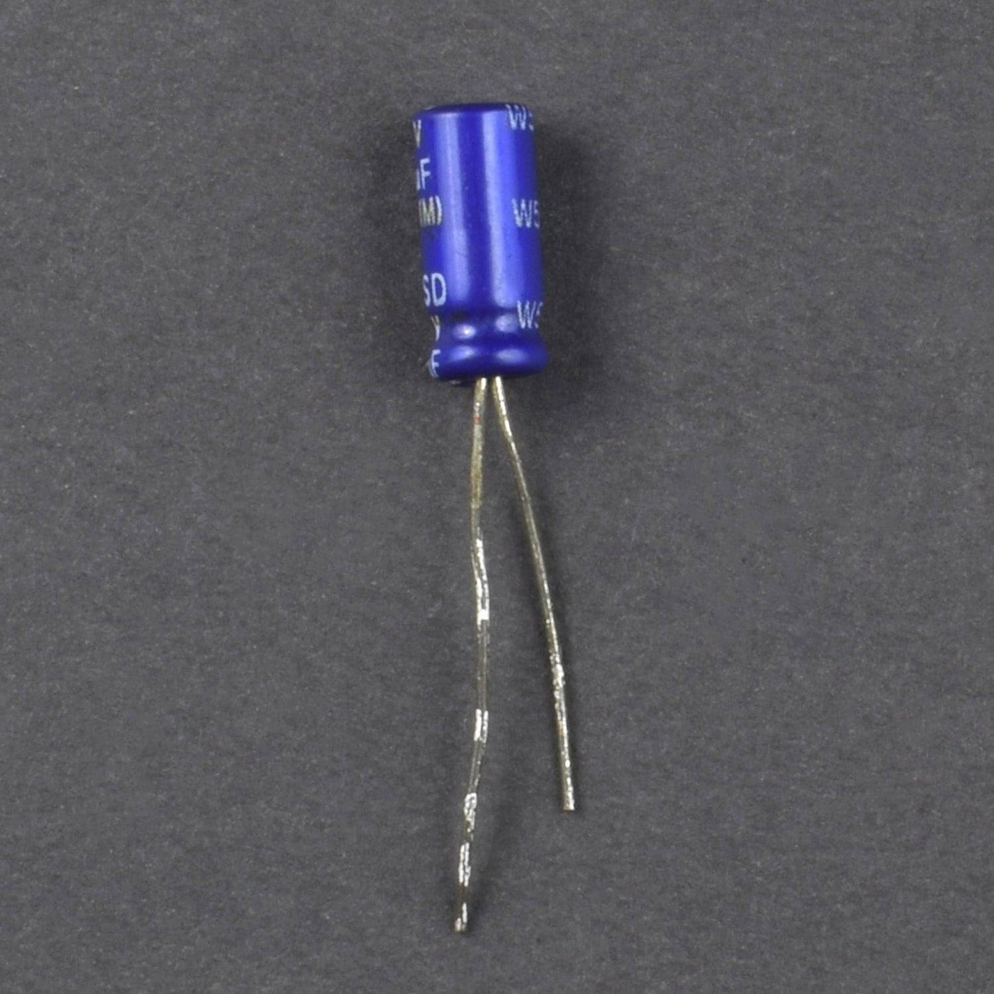
- 2x Electrolytic Cap 16V 100uF
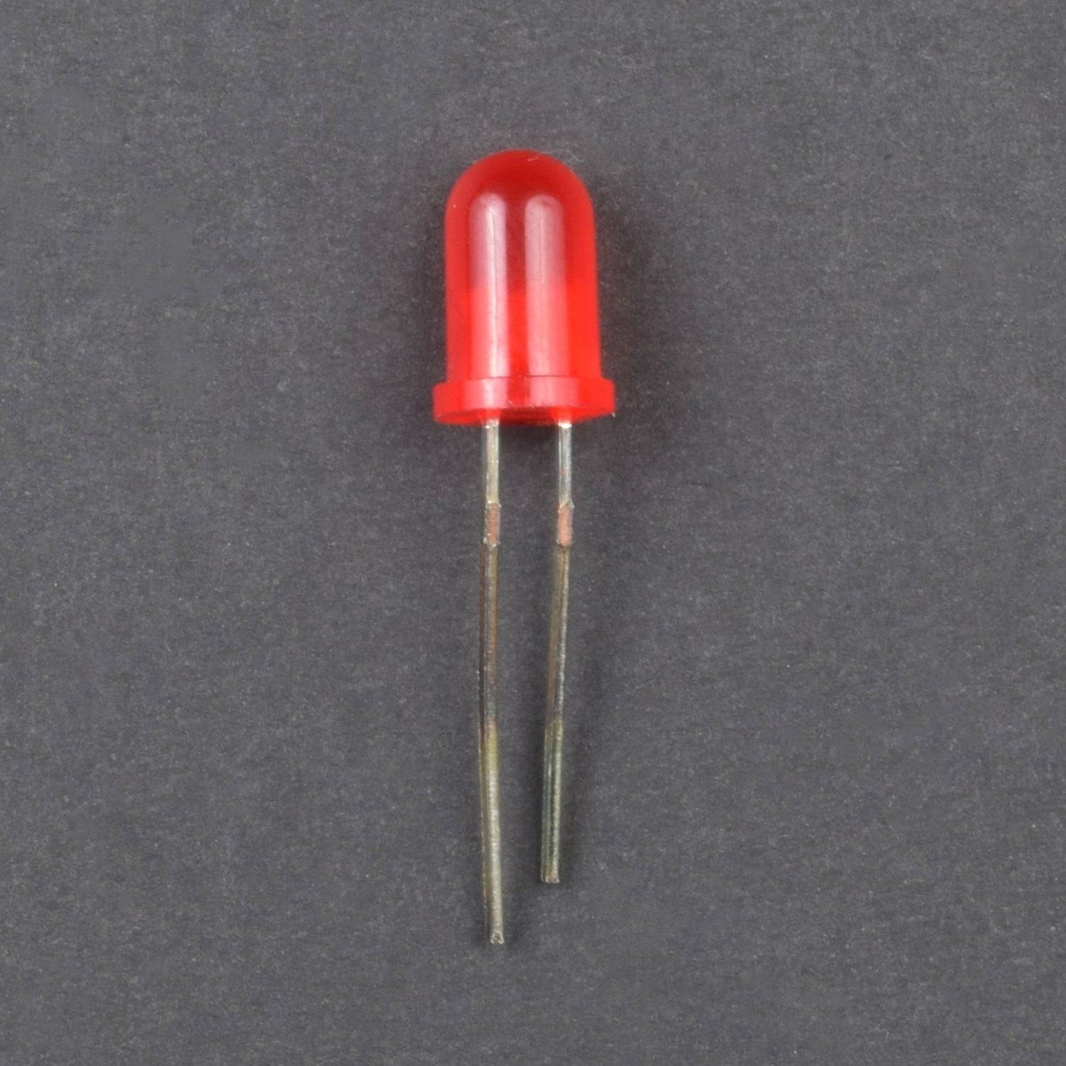
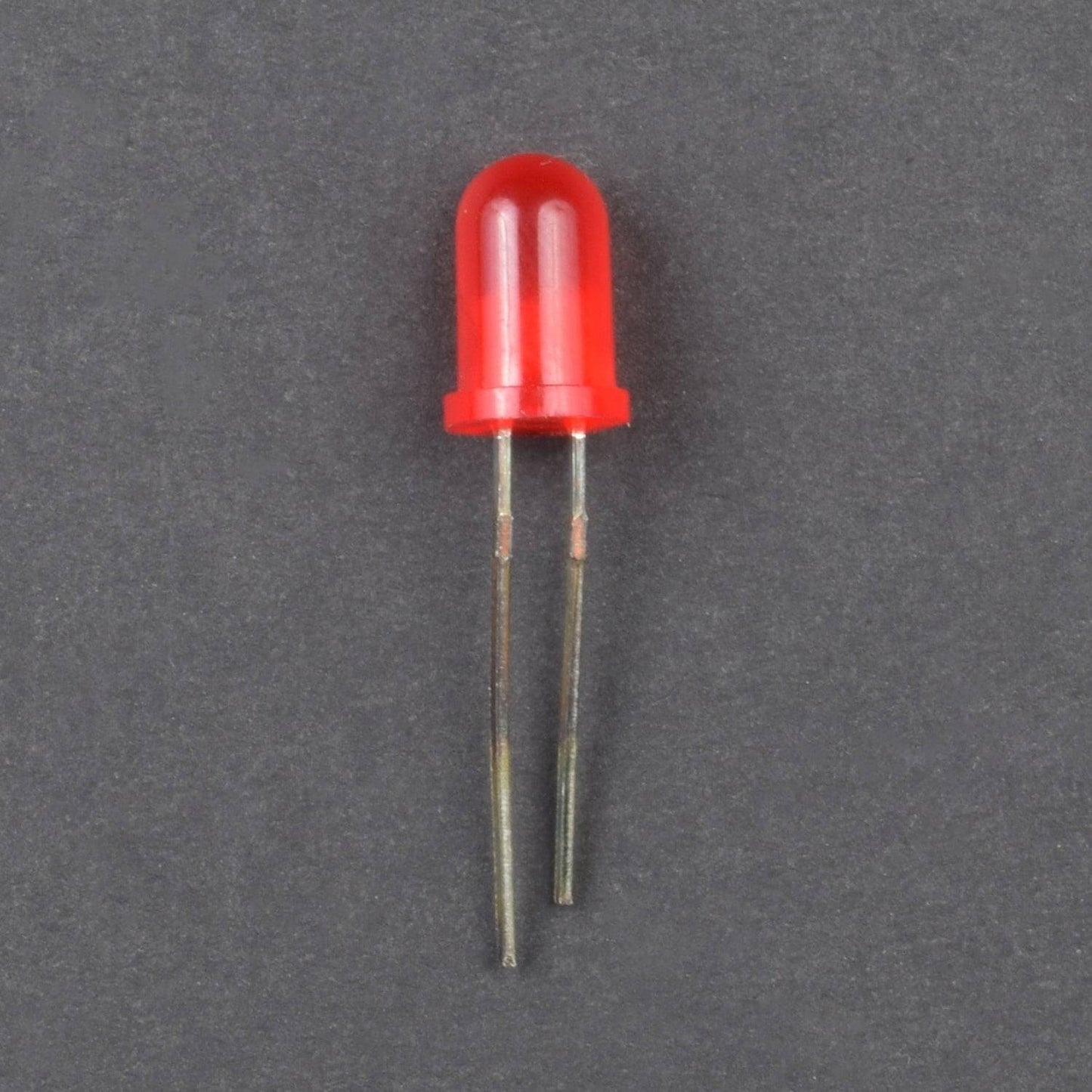
- 4x 5mm LED
- 2x DPDT Rocker switch
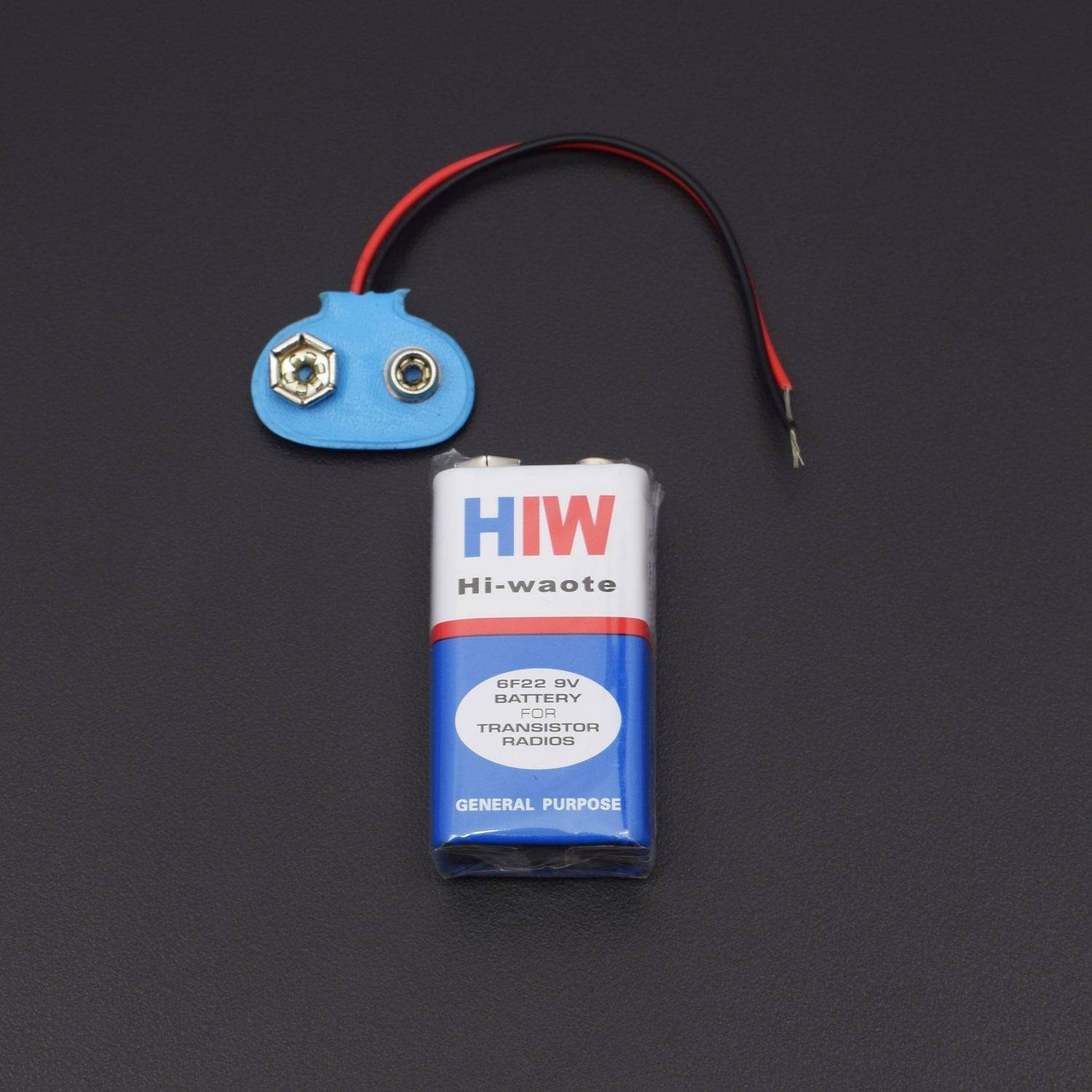
- 1x 9V Battery Clip
- 1x 9V Battery
- 1x Plastic Enclosure
- 1x Robot 3-wheel Chassis kit
- 1x SPST Rocker Switch
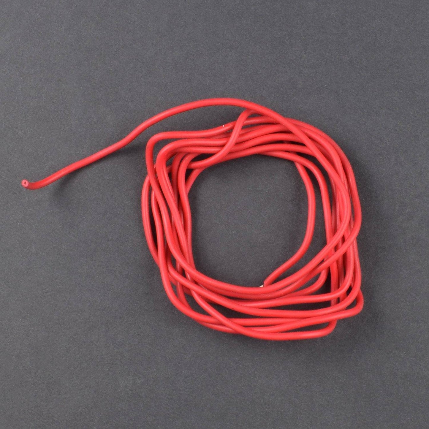
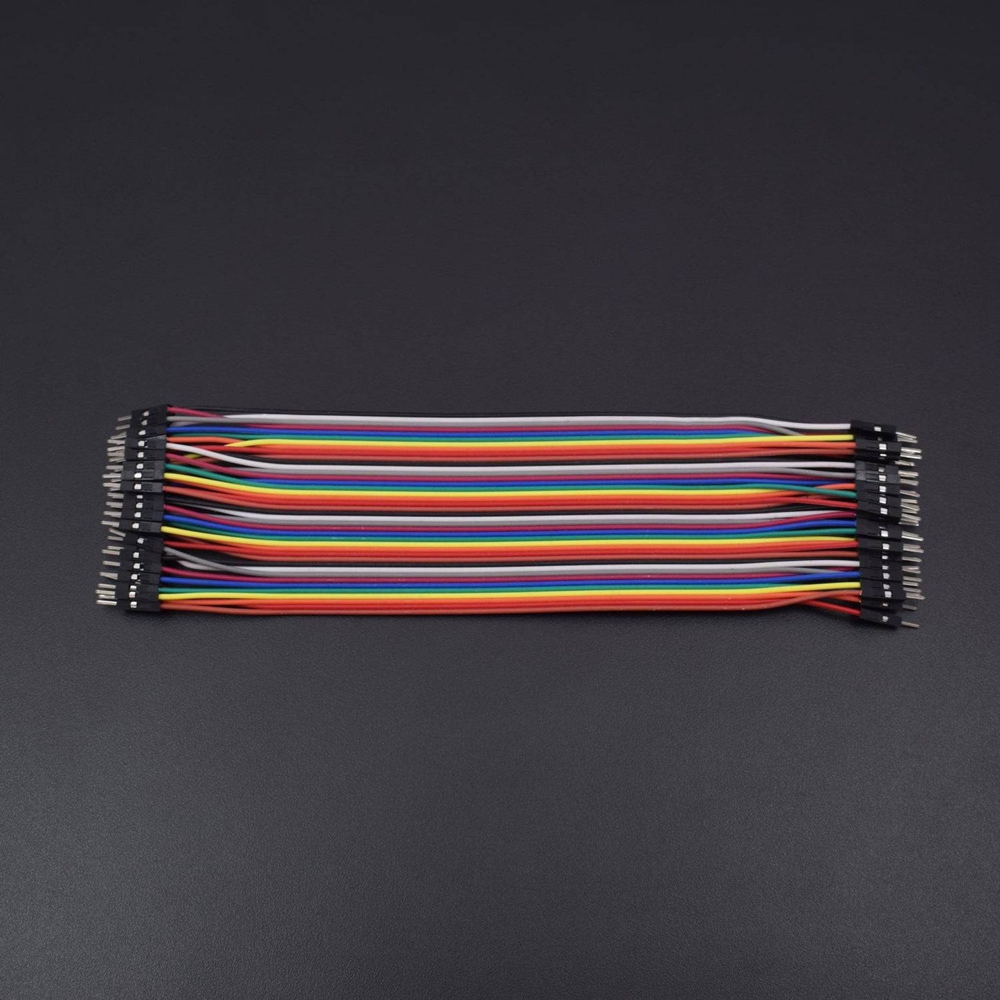
- 1x Hook-Up Wires AWG22 Solid
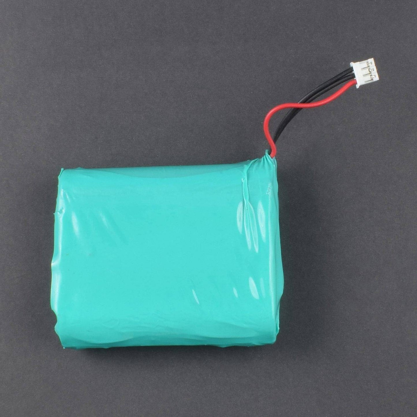
- 1x 12V lithium-ion battery
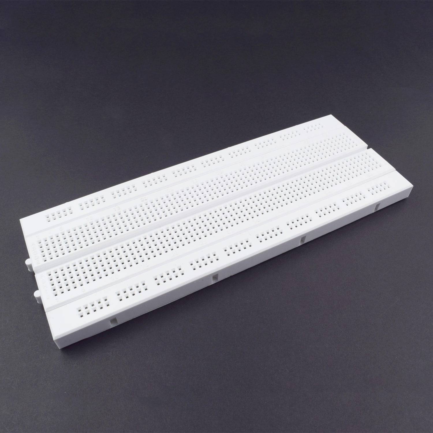
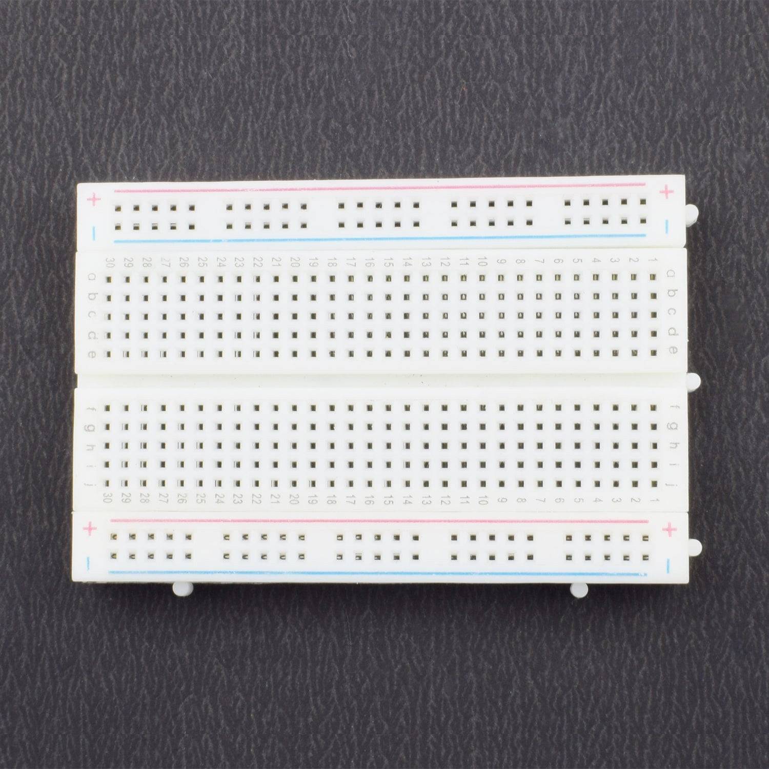
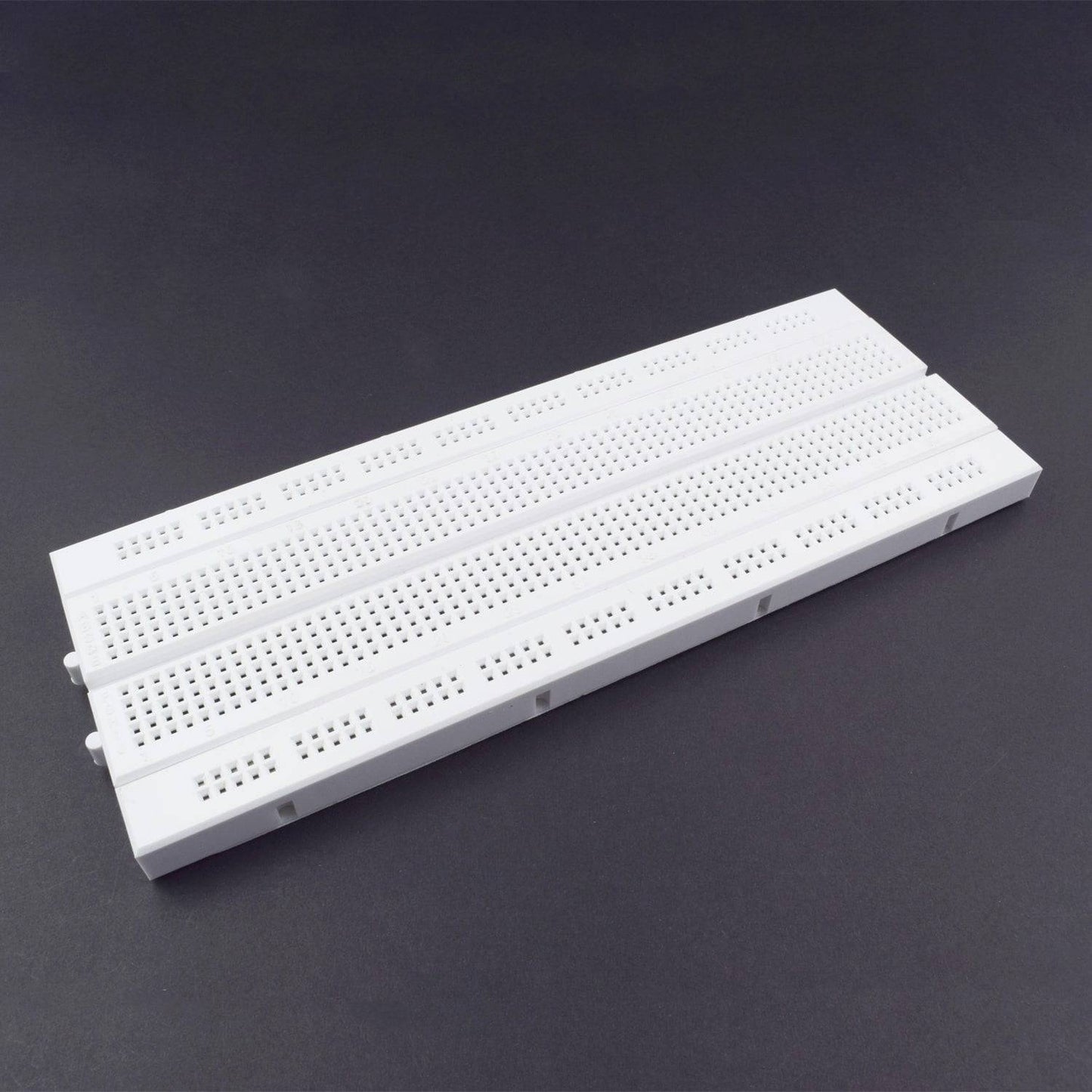
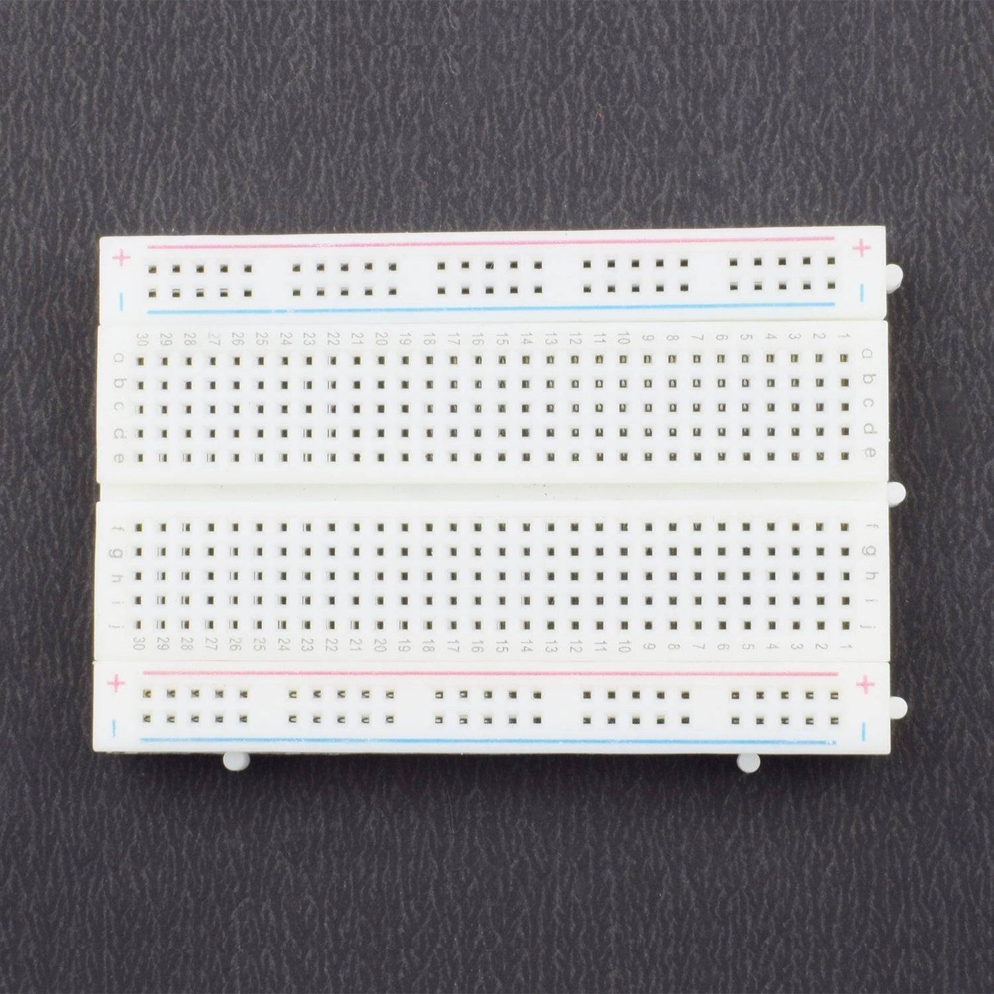
- 1x breadboard (400pins)
- 1Xbreadboard (800 pins)
SPECIFICATIONS
434 Mhz Transmitter Reciever Kit
- Frequency 434 MHz
- Transmitter: Saw filter based ASK hybrid transmitter
- Transmitter supply voltage: 3~12V.R
- receiver: ASK superheterodyne receiver with PLL synthesizer and crystal oscillator.
- Receiver Supply voltage: 5V
- Receiver IF frequency: 500 kHz
- Receiver Sensitivity: -105dBm
- Receiver Supply current: 2.3mA
- Output power: 4~16dBm
- Turn on time: 20mS from power is switched on.
- Data rate 200bps to 3Kbps depending on the supply.
- Operating voltage: 5 Volts
PIN DESCRIPTION
Voltage Regulator 7805

Led

Electrolytic Capacitor

L293DE Motor Driver IC

HT12D Decoder IC

HT12E Encoder IC
.jpg)
434 Mhz Transmitter Receiver Kit
Transmitter PCB Layout

Receiver PCB layout

HOW TO MAKE REMOTE

Cut the Parts as given in picture above:

Remote will be shown like this
.jpg)

Connection made as given in picture above for DPDT Switch
CIRCUIT CONNECTION
Switch Connection

Transmitter (Remote Controller) connection
![]()
- Connect Pin 1 to 9 and pin 14 to the ground of HT12E IC
- Connect pin 16 and 15 via 1M resistor of HT12E IC
- Connect Pin 17 of HT12E to data pin of RF link transmitter and pin 18 to the +5v ( Positive rail on breadboard )
- Connect pins 10,11,12,13 to the DPDT Rocker switch (s2 and s3 as shown in the photo.
- Connect Pin 1 of RF link transmitter to GROUND and pin 3 (VCC) to +5v and connect antenna to pin 4.
- Connect the ground pin of 7805 voltage regulator to the ground ,Vin to switch s1 one point and other point to 9v battery then c1(100uf)’s positive Vin and negative to ground and then Vo to Positive rail and c2 capacitor. Positive to Vo and negative to gnd.
- 1k resistor one terminal to ground and other terminal to negative of led and positive of led to the positive rail.
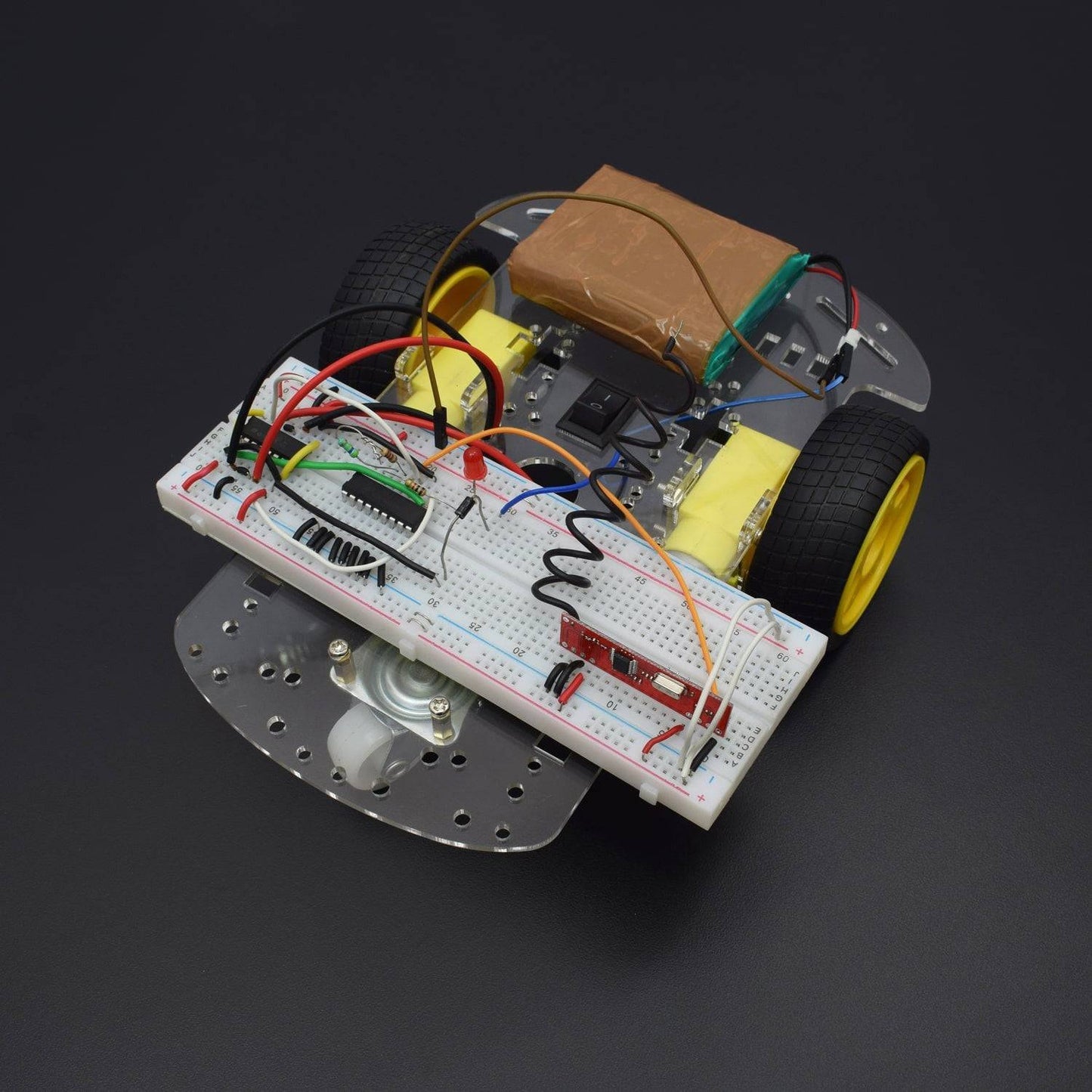
Receiver (RC car) Connection
.jpg)
- Place the decoder IC(HT12D) the motor driver IC and the RF link receiver to the breadboard
- Connect the 1 to 9 pins of decoder IC to the ground
- Pin ten of ht12d goes to pin 2 of L293d, pin 11 goes to pin 7, pin 12 goes to pin 10 and pin 13 goes to pin 15.
- Pin 14 of ht12d goes to pin 2(data) of RF link receiver.
- Pin 15 is connected to pin 16 of HT12D via 50k resistor.
- Pin 17 is connected to 1k resistor one terminal and other terminal of resistor to the -ve of led and the positive of led to the +5v rail of breadboard.
- Pin 18 is also goes to +5v rail.
- Pin no. 1,8,9,16 of L293D goes to the +5v rail.
- Pin no. 4,5,12,13 to the ground.
- Pin 3 and 6 connected to motor m1 and pin no. 11 and 14 to the motor m2.
- All three ground pins in the RF link receiver goes to GND rail,vcc1 and vc2 to +5v rail and antenna is connected to
- Pin 8(ant).
- Now connect one 1N4001 Diode to breadboard connect Positive of diode to the one point of SPST Rocker Switch and other point of
- Switch to the 12v li ion battery positive point.
- Negative point of diode to the positive rail.
If you want to make this RC car on PCB:
