


Generic
Make a Quadcopter using KK 2.1.5 Flight Controller - KT926
Make a Quadcopter using KK 2.1.5 Flight Controller - KT926
SKU:KT926
100 in stock
Couldn't load pickup availability
- For Bulk Order Click Here
- Need Customer Support?
- Free Delivery Above 999/-
Note: In case you receive a damaged or faulty product, please return it in the original box with all foam and packaging. Returns will not be accepted if further damage occurs due to improper packing.
If you order a product that is currently in Preorder, and the price of that item increases in the future, you will be required to pay the difference in price.
For refund/return/replacement, call us at +91 95995 94520 or email us at support@rees52.com
Delivery Time
Delivery Time
- Delivery time with the Express Shipping option is 2-3 working days, and with the Standard Shipping option is 5-6 working days. It varies based on location, reliant on courier services.
- Delivery time if the order item is on Preorder Status is 15-20 working days.
COD (Cash on Delivery)
COD (Cash on Delivery)
- For COD you have to pay extra charges of Rs 350/- before the shipment. (We will share the company QR Code, UPI ID or Account details for the same)


Description
A quadcopter, also called a quadrotor helicopter or quadrotor, Is a multirotor helicopter that is lifted and propelled by four rotors. Quadcopters are classified as rotorcraft, as opposed to fixed-wing aircraft, because their lift is generated by a set of rotors (vertically oriented propellers).
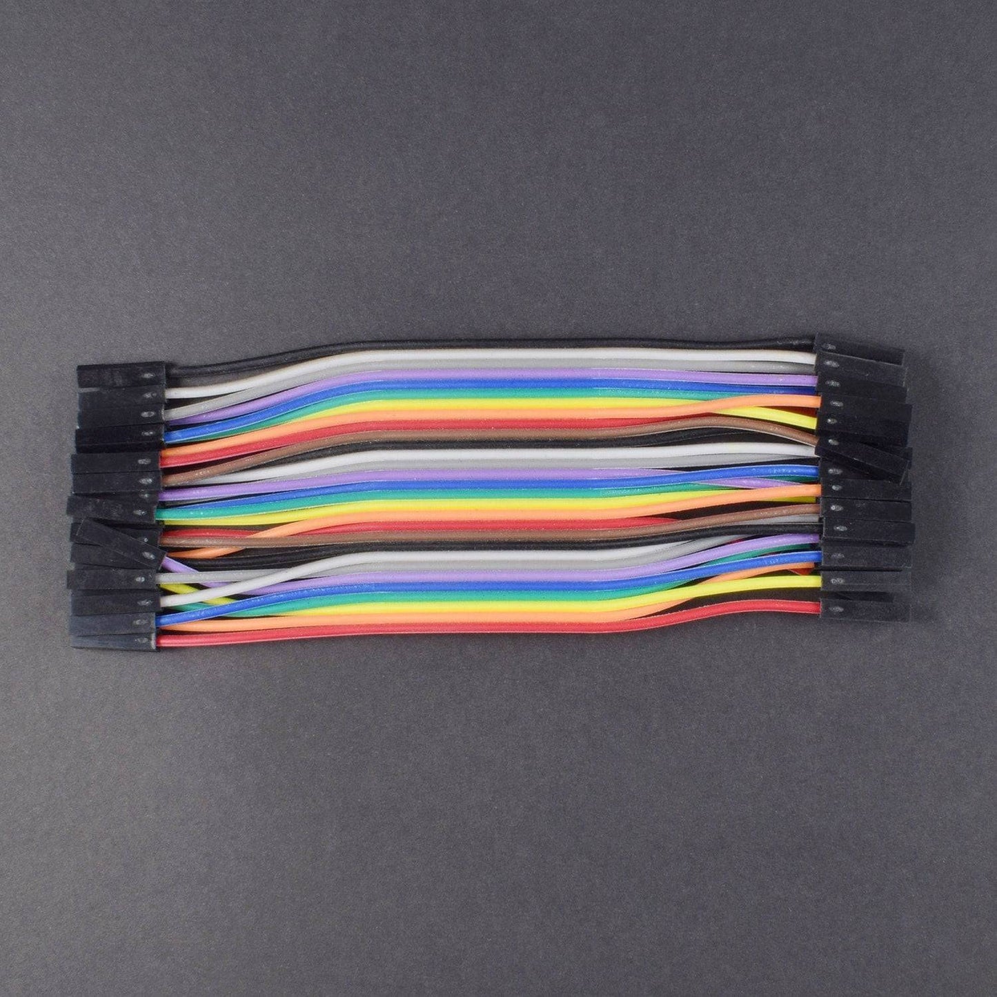
HARDWARE REQUIRED
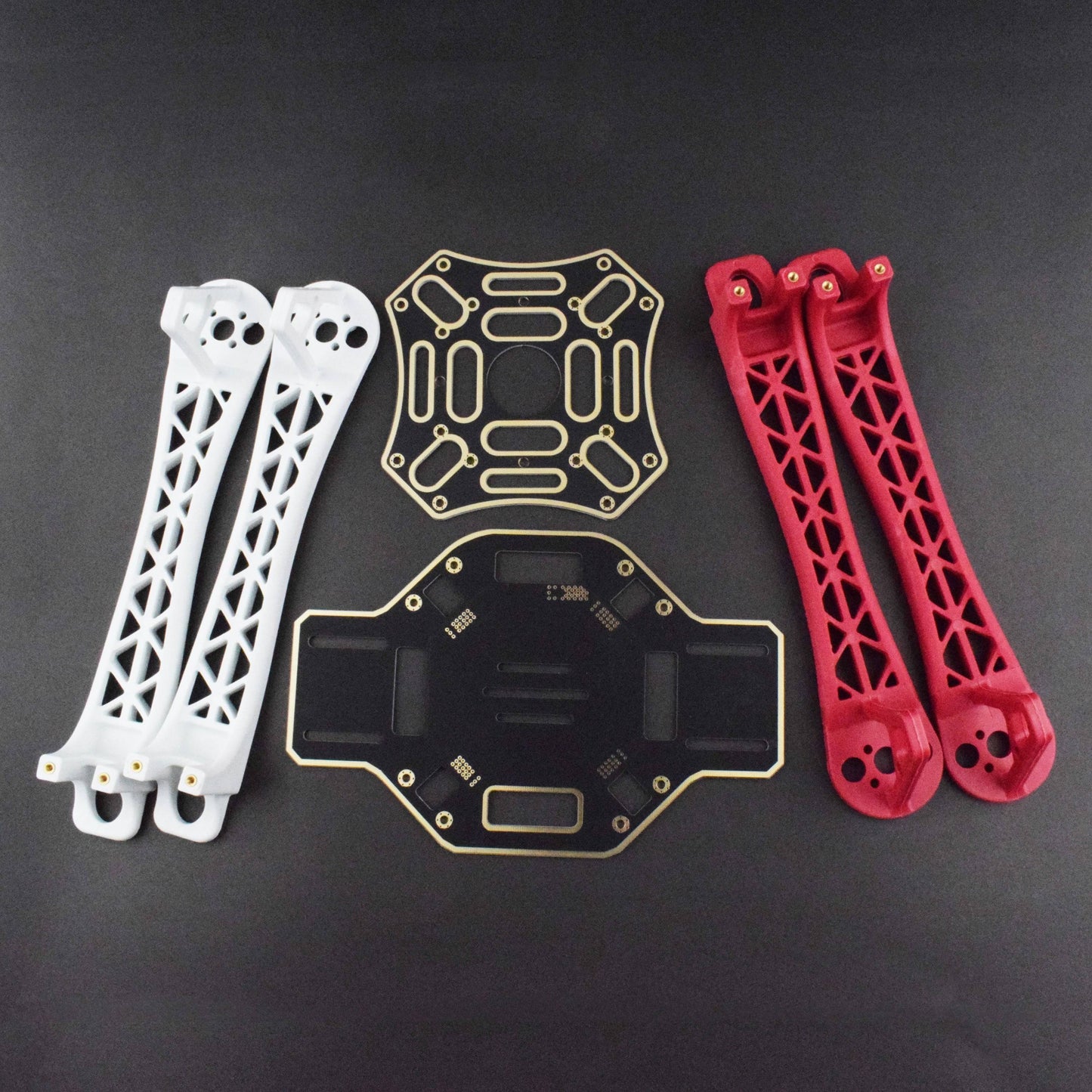
1) Quadcopter Frame (Preferably one which has a built-in Power Distribution board)
2) Microcontroller (KK 2.15 Flight Controller)
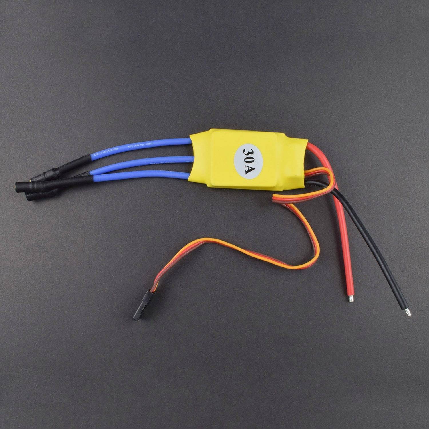
3) Electronic Speed Control (30 Amps) (4 pieces)
4) Brushless Motor (850KV) (4 pieces)
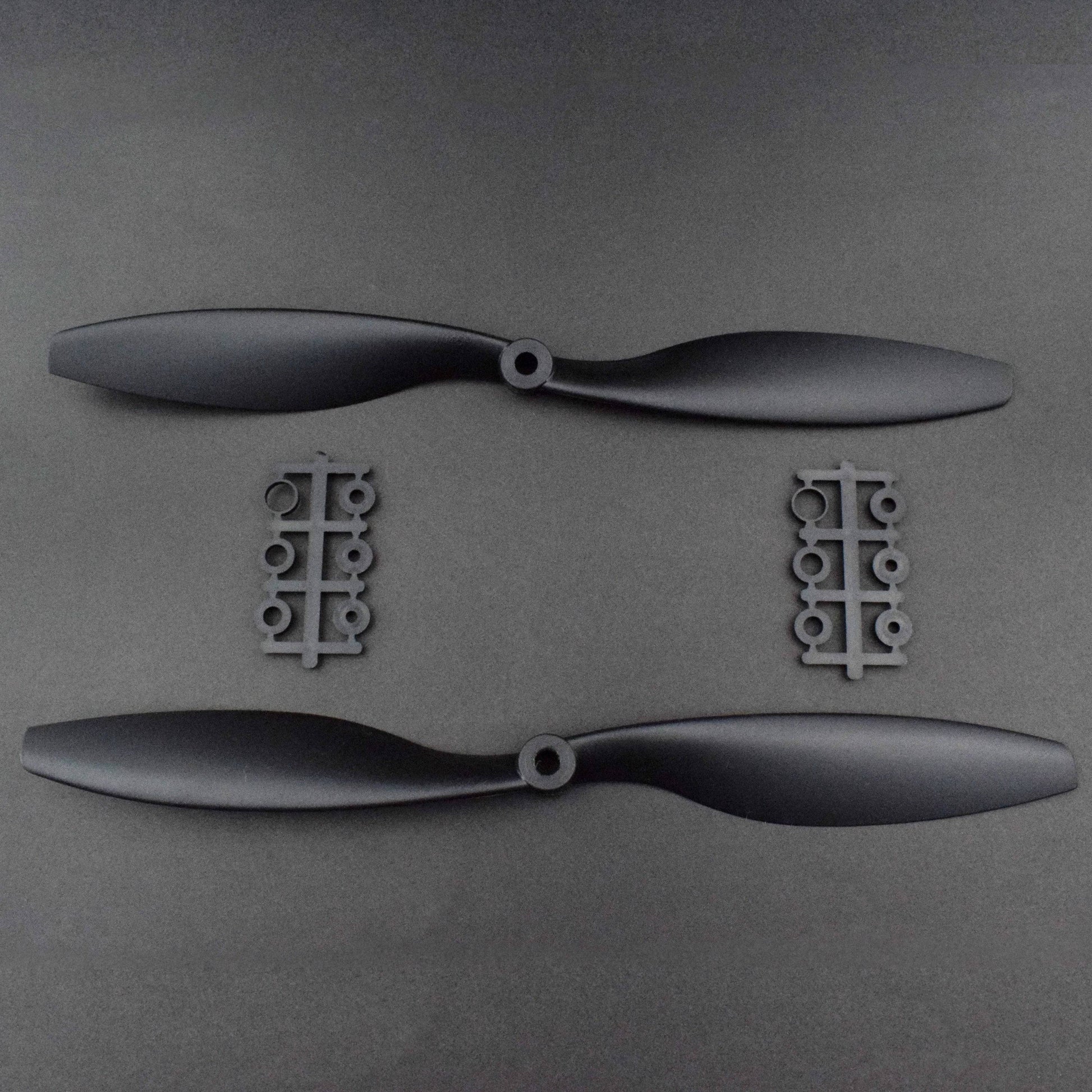
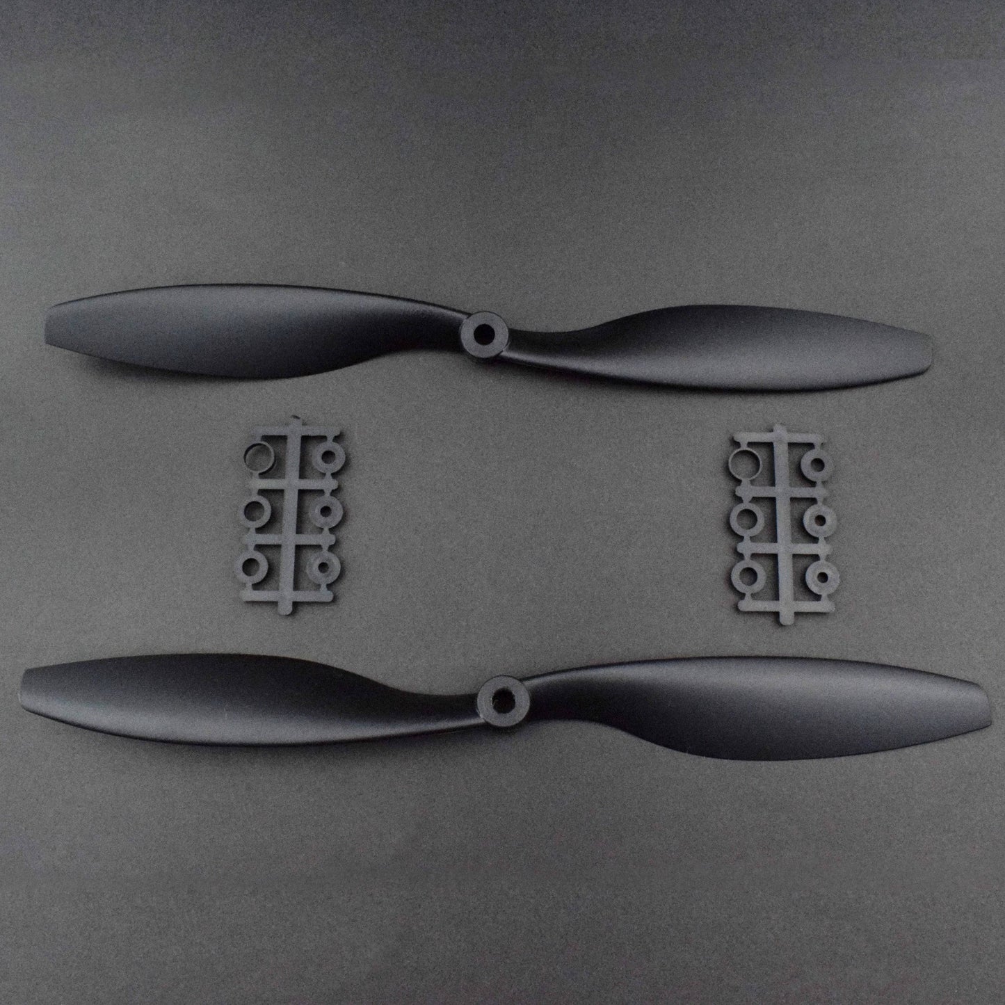
5) Propellers (2 sets)
6) Power Distribution Board (Not needed if the frame has a built-in one)
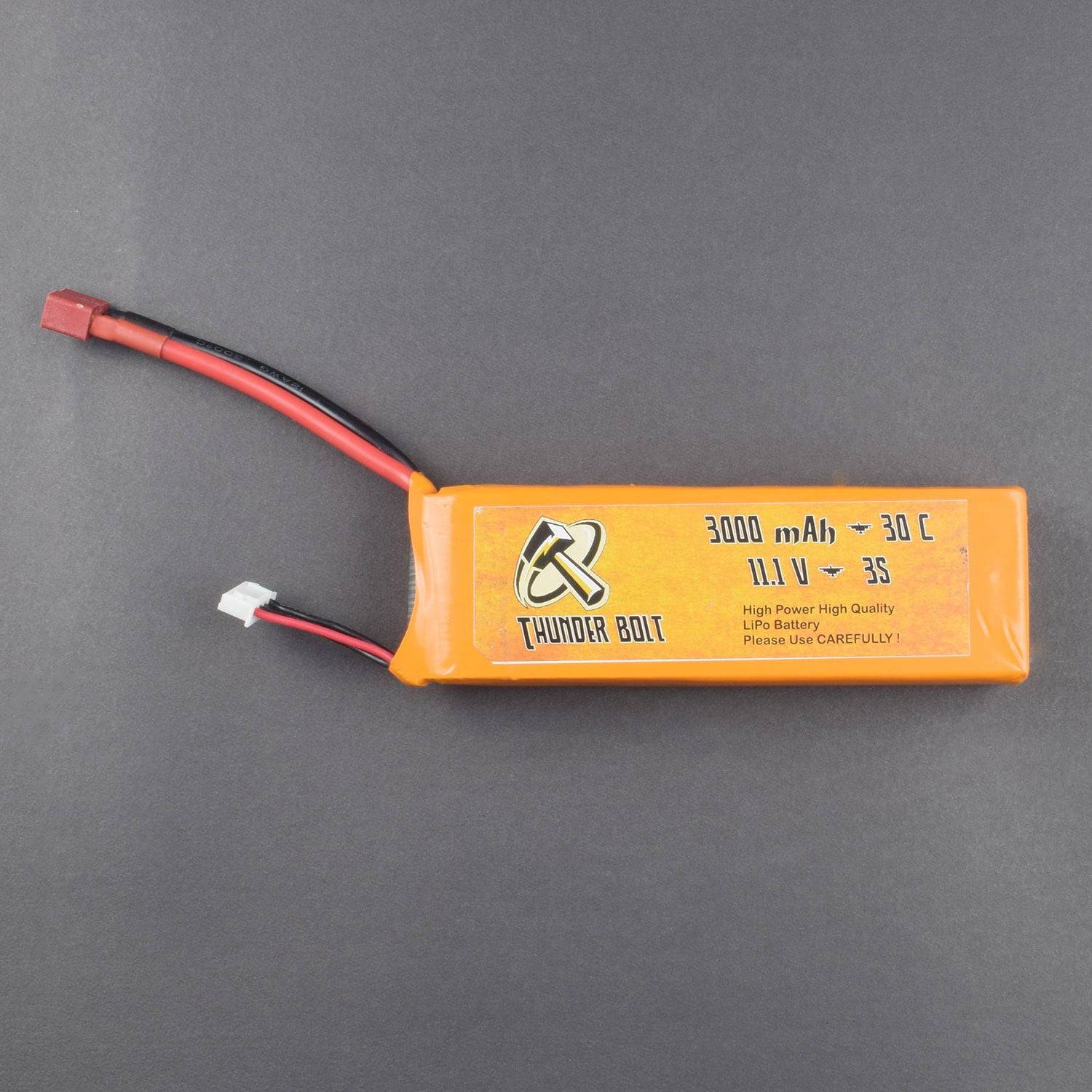
7) Lithium-Polymer 2300 mAH Battery
8) Fly Sky FS-T6 Controller includes the Receiver
SPECIFICATIONS
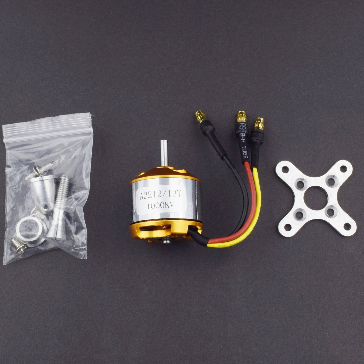
1000 KV BRUSHLESS MOTOR
- A2212/13.RPM/V: 1000KV.Batteries: 2-3 Li-Poly
- Efficiency: 80%.
- Current: 4-10A (>75%).
- No load current: 10V/0.5A.Max.
- transient current: 12A/60S
- Shaft diameter: 3.17mm.
- Dimensions: 27.5*30mm.
- The weight limit for the compatible model plane: 300-900g.
- Compatible propeller model: APC 10*5/ APC 11*5.5/ APC 10*4.7
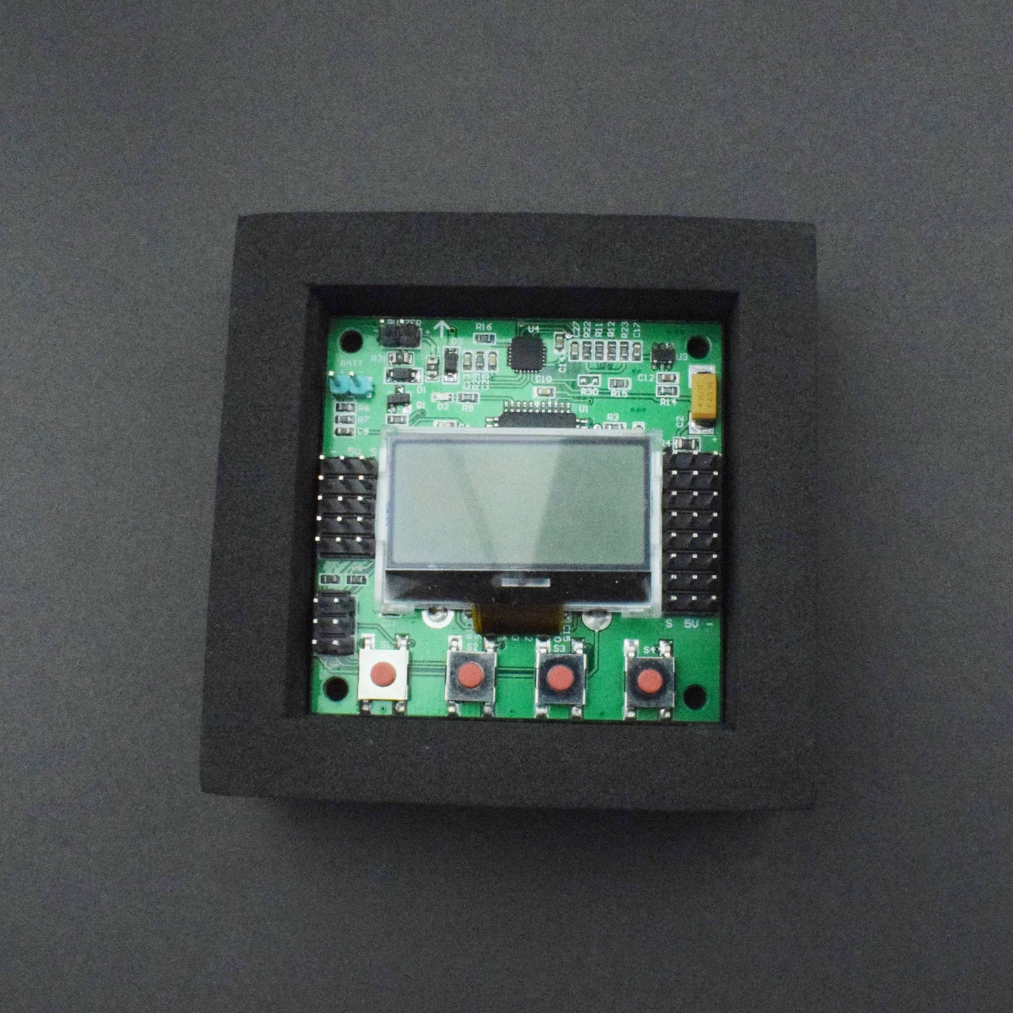
KK 2.1 Multi-Rotor Flight Control board
- Size: 50.5mm x 50.5mm x 12mm
- Weight: 21 Grams (Inc. Piezo buzzer)
- IC: Atmega644 PA
- Gyro/Acc: 6050MPU
- Auto-level: Yes
- Input Voltage: 4.8-6.0V
- AVR interface: standard 6-pin.
- Signal from Receiver: 1520us (5 channels)
- Signal to ESC: 1520us
- Firmware Version 1.6
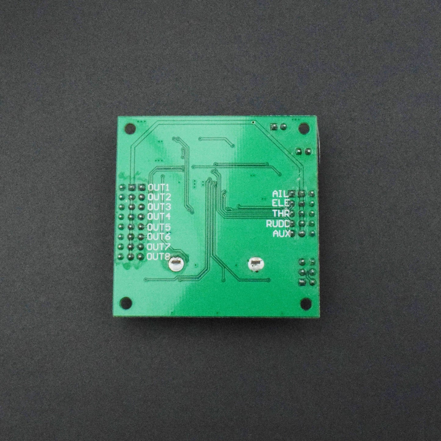
PIN DESCRIPTION
KK 2.1.5 Multi-Rotor Flight Controller Board

KK2.1 Multi-Rotor controller manages the flight of (mostly) multi-rotor Aircraft (Tri- copters, Quadcopters, Hex copters, etc). Its purpose is to stabilize the aircraft during flight and to do this, it takes signals from on-board gyroscopes (roll, pitch, and yaw) and passes these signals to the Atmega324PA processor, which in turn processes signals according to the user-selected firmware (e.g. Quadcopter) and passes the control signals to the installed Electronic Speed Controllers (ESCs) and the combination of these signals instructs the ESCs to make fine adjustments to the motors rotational speeds which in-turn stabilizes the craft. The KK2.1 Multi-Rotor control board also uses signals from your radio system via a receiver (Rx) and passes these signals together with stabilization signals to the Atmega324PA IC via the aileron; elevator; throttle and rudder user demand inputs. Once processed, this information is sent to the ESCs which in turn adjust the rotational speed of each motor to control flight orientation (up, down, backward, forwards, left, right, yaw)
INITIAL SETUP
First, take all the parts that are required to build the frame. Take all four arms of the drone and fix it on the PCB board. Use the screw to tighten the arms with the PCB. Now take the landing gears and fix it in the bottom side of the frame. Then connect the upper pcb to the drone and fix it with the screw.

At the end of each arm, you have to connect one brushless DC motor. It is recommended to use the brushless motor of 1000 KVA. Fix the motors at the arm by using the screws.

How to connect ESC to a brushless motor?
Finally, you have to connect the ESC to the brushless motors. There are three output pins of ESC. You have to connect the left and right pins of the ESC with the left and right pins of the brushless motor. Then connect the middle pin of the ESC with the middle pin of the brushless motor. If you need to change the direction of the brushless motor in the future, then you simply interchange the connection of the left and right pin of ESC with the brushless motor.

How to bind flysky transmitter and receiver?
The next important thing is to bind the receiver with the transmitter. For binding the receiver and transmitter you need to follow some basic steps which are –
(1) Give a 5-volt power supply to the receiver. You can use an ESC to power up the receiver. You can see a red light blinking inside the receiver.
(2) Now connect the binding cable to the bat channel of the receiver.
(3) Keep pressing the bind button in the transmitter, and then switch on the transmitter.
(4) At that time the red light of the receiver will stop blinking and the light is in a standstill position. This indicates that the binding is done successfully.

Now it’s time to build the circuit by using the kk 2.1.5 flight controller. For this, you have to place the kk flight controller in the middle of your quadcopter. Here we are making X mode quadcopter. For an x-mode quadcopter, the configuration of the kk flight controller is like this –
How do I connect my ESC to my flight controller?
Once you place the kk flight controller in your drone, you need to connect the ESC to the flight controller. Now connect the four esc in the four respective pins of kk flight controller. Always remember that the signal pin of the ESC will be placed just beside the LCD screen. Also, you need to make the connection between the receiver and the flight controller. Connect all channels of the receiver with the respective channels of the flight controller.

How do I connect my kk flight controller to my receiver?
(1) Channel 1 of receiver – Aileron channel
(2) Channel 2 of receiver – Elevator channel
(3) Channel 3 of receiver – Throttle channel
(4) Channel 4 of receiver – Rudder channel
(5) Channel 5 of receiver – Aux channel
KK 2.1.5 flight controller setup –
Now it’s time to set up the kk 2.1.5 flight controller. Give the power supply to the drone and follow the steps to set up the flight controller.
(1) At first click on the menu button and then go to the “load motor layout”.
(2) From here you have to select the proper layout of your drone. In our case, the layout will be “quadcopter x mode”.
(3) Then open the acc calibration. Place the quadcopter on a flat surface and wait for five seconds. At this time the acc will be calibrated to its proper value. Do not move the drone during this time period.
(4) Then go to the self-level settings and select the self-level for always. This setting will help the quadcopter to balance itself. As a result, you will get a stable fly.
(5) After this calibrate the PID values for the aileron, elevator, and rudder.
(6) Finally do the ESC calibration and throttle calibration for better results.

Finally, you have done all the important steps including circuit building, setup of kk flight controller, and calibration. So it's time to fly the drone in the sky. For this, you have to connect the battery and propeller to the drone.
Accessing the Leveling Mode
1. You can access the self-leveling mode either from the settings of STICK or AUX channel.
2. When set to AUX Mode you must connect a spare channel usually CH5 or Ch6 and changing the Transmitter switch position will enable/disable Self-Levelling mode.
3. When set to STICK Mode to go into Self-Levelling Mode, you must set the Throttle to Minimum and set maximum Left Rudder whilst at the same time, setting maximum Left Aileron to disable SL or maximum Right Aileron to enable SL.
Flight controller Sound
1. One Beep (short beep, 2-sec delay) is emitted when the board is armed and the throttle is closed, this is for safety reasons so you know it’s armed.
2. One Long Beep is emitted when the board is either Armed or Disarmed.
Status Screen
Displays the message "SAFE" and the KK2 will not arm unless it says "OK".
Status Screen
Error messages can only be reset by cycling the power, except for the "sensors not calibrated" message, which is reset after a successful sensor calibration.
Error messages include lost RX connection.
The KK2.1 has an auto-disarm function and will disarm itself after 20 sec if the throttle is idle. For extra safety. Can be turned on/off in "Mode Settings" menu
Lost Model Alarm
The KK2.1 has a lost aircraft alarm and starts to beep (1 sec on and 4 sec off) after 30min of no activity (arm/disarm).
Model Type Supported
Dualcopter
Tricopter
Y6 Quadcopter +
Quadcopter X
Hexcopter +
Hexcopter X
Octocopter +
Octocopter X
X8 +
X8 X
H8
H6
V8
V6
Aero 1S Aileron
Aero 2S Aileron
Flying Wing
Singlecopter 2M 2S
Singlecopter 1M 4S
TOOLS AND KNOWLEDGE
1) Basic soldering skills
2) Alan's keys
3) Shrink tubes(Preferably Turnigy)
4) Zip ties (To hold the ESC's onto the frame)
5) Glue gun (To put all over the connections to avoid any contact between them)
ASSEMBLE AND CONNECT

1) The motors and ESC's can be connected to each other via direct soldering or using Bullet Connectors of 4mm dimension.
2) The ESC's are then connected to the power distribution board, or in this case directly to the frame which has an inbuilt power distribution board, by soldering. (Make sure to know if the ESC's are supposed to be flashed or not, mine did not required to do so.)
3) Once this is done, solder the battery wire to the frame.
4) Once all the soldering work is done, and the hardware is setup, connect the KK Board(again flashed with the latest firmware) with the ESC servo wires, and Receiver.
PLUG IN THE BATTERY AND TEST YOUR QUADCOPTER

If your code is all correct and your connections are all good you should see the LCD screen on the board lit up, from where you can easily calibrate both the Accelerometer and Magnetometer.
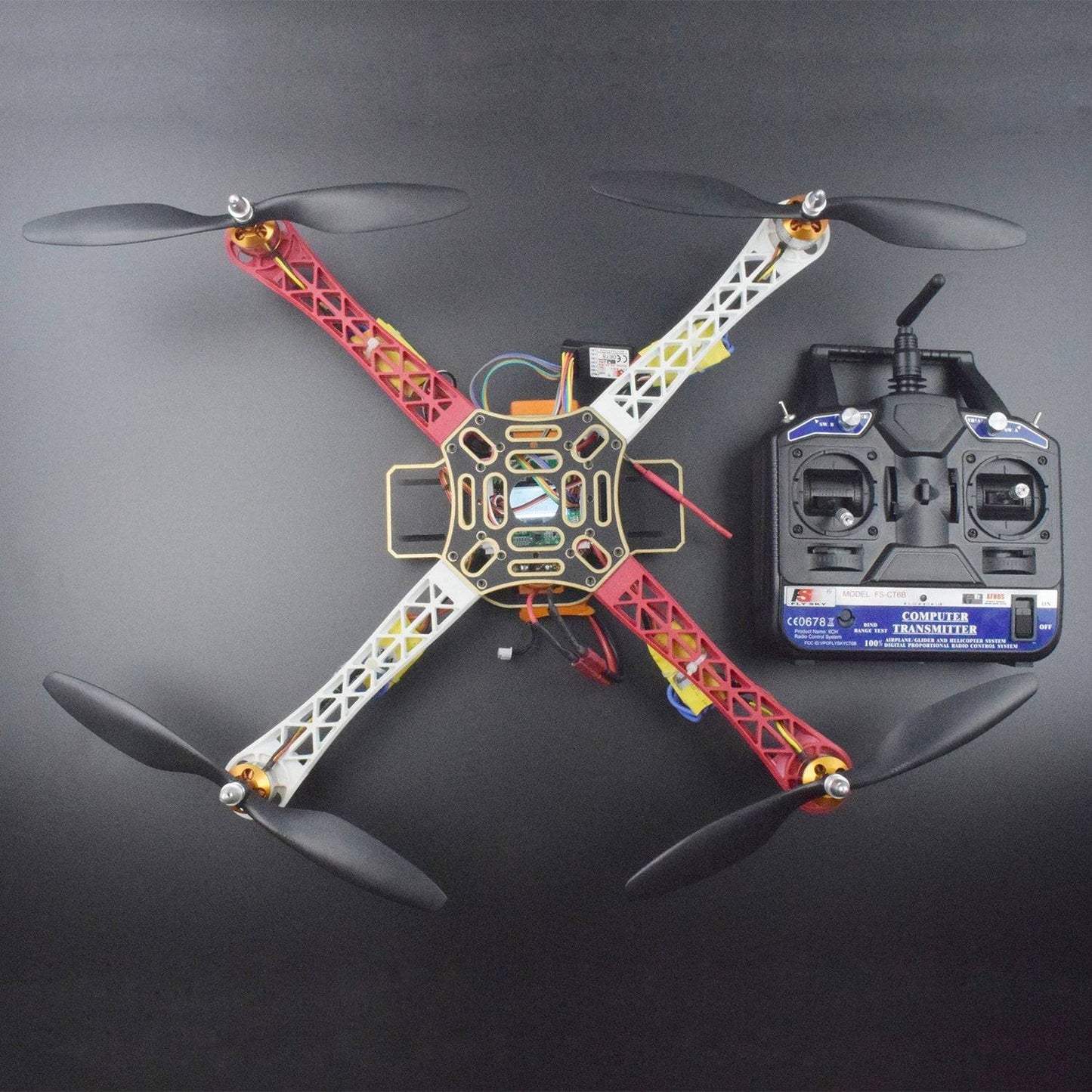
Kit Included:
- 1 x Quadcopter Frame
- 4 x ESC 30A
- 4 x A2212 Motor 1000KV
- 1 x KK 2.1.5 Flight Controller
- 1 x Flysky CT6B Transmitter with Receiver
- 1 x LiPo Battery 3000mAh
- 2 x 1045 Propeller (Pair of 2)