


vendor-unknown
Make a power failure alarm using 555 timer IC and piezo buzzer - KT947
Make a power failure alarm using 555 timer IC and piezo buzzer - KT947
SKU:KT947
1000 in stock
Couldn't load pickup availability
- For Bulk Order Click Here
- Need Customer Support?
- Free Delivery Above 999/-
Note: In case you receive a damaged or faulty product, please return it in the original box with all foam and packaging. Returns will not be accepted if further damage occurs due to improper packing.
If you order a product that is currently in Preorder, and the price of that item increases in the future, you will be required to pay the difference in price.
For refund/return/replacement, call us at +91 95995 94520 or email us at support@rees52.com
Delivery Time
Delivery Time
- Delivery time with the Express Shipping option is 2-3 working days, and with the Standard Shipping option is 5-6 working days. It varies based on location, reliant on courier services.
- Delivery time if the order item is on Preorder Status is 15-20 working days.
COD (Cash on Delivery)
COD (Cash on Delivery)
- For COD you have to pay extra charges of Rs 350/- before the shipment. (We will share the company QR Code, UPI ID or Account details for the same)


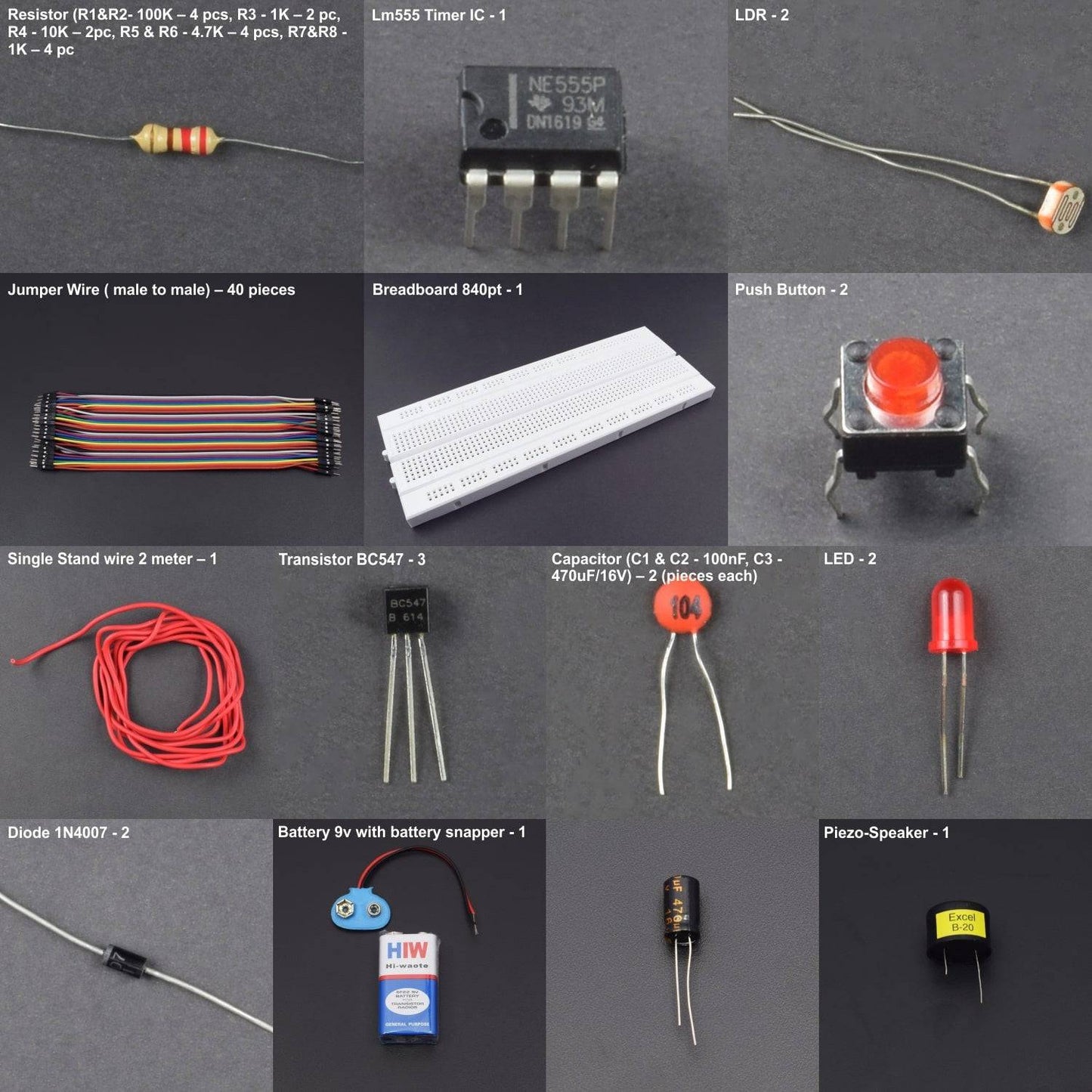


KIT INCLUDES:
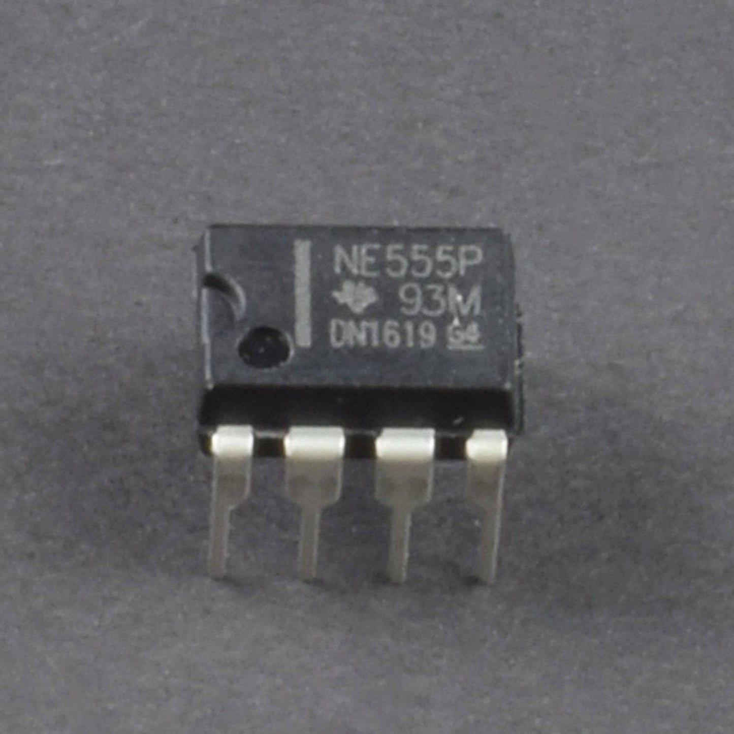
- NE555 Timer IC - 1
- Transistor BC547 - 3
- Diode 1N4007 - 2
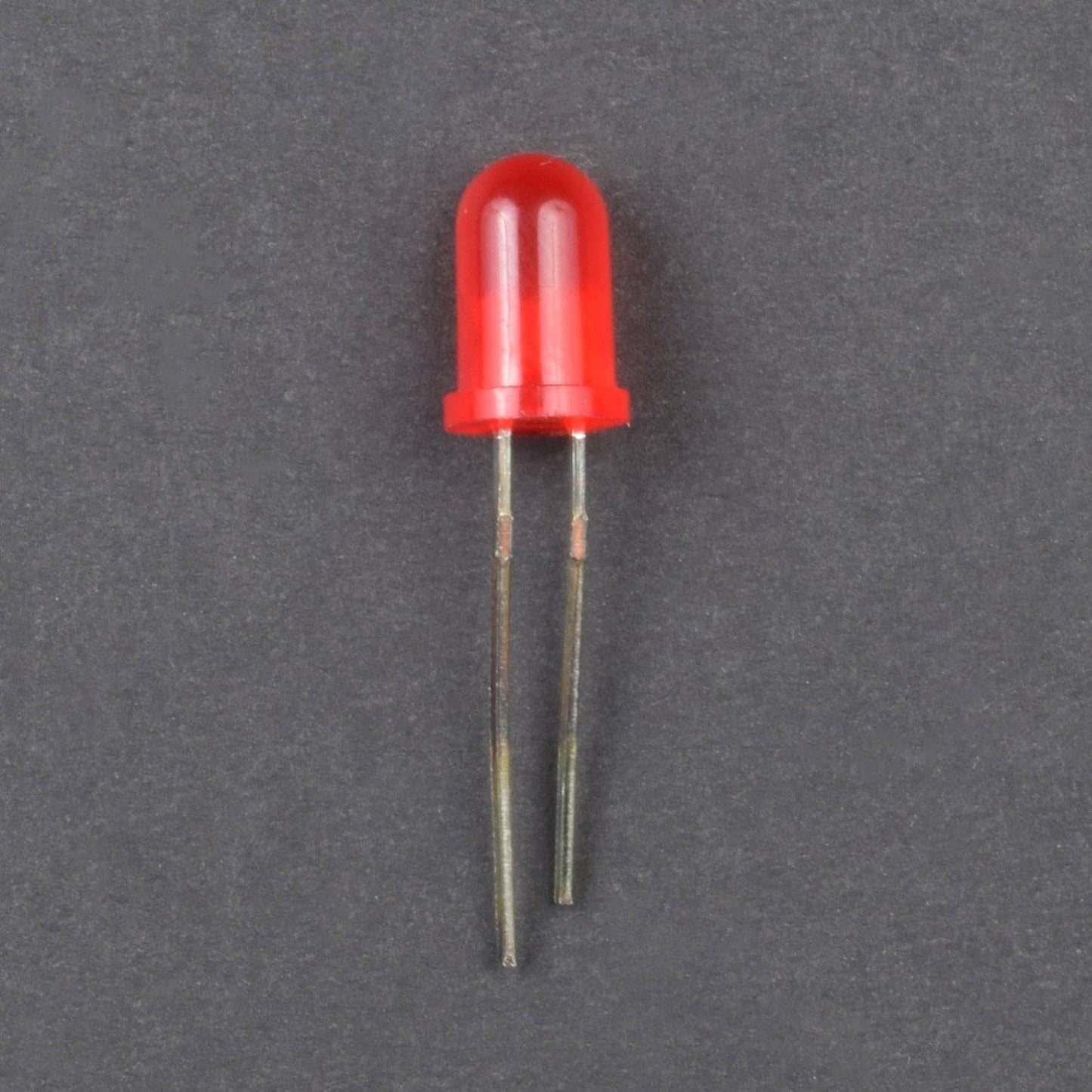
- LED - 2
- Resistor (R1&R2- 100K – 4 pcs , R3 - 1K – 2 pcS,R4 - 10K – 2pc , R5 & R6 - 4.7K – 4 pcs , R7&R8 - 1K – 4 pc
- Capacitor (C1 & C2 - 100nF, C3 - 470uF/16V) – 2 pieces each)
- Push Button - 2
- LDR - 2
- Piezo-Speaker - 1
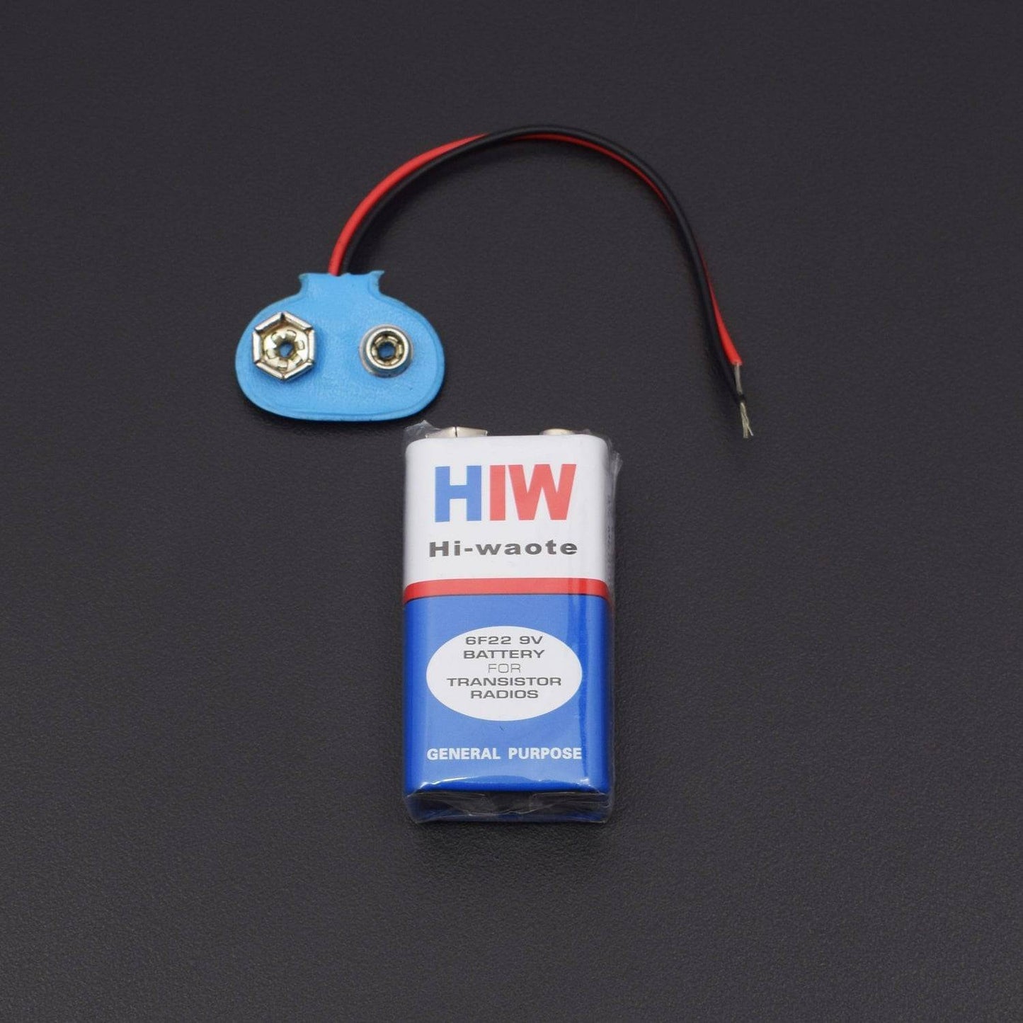
- Battery 9v - 1
- battery snapper - 1
- Jumper Wire ( male to male) – 40 pieces
- Single Stand wire 2 meter – 1
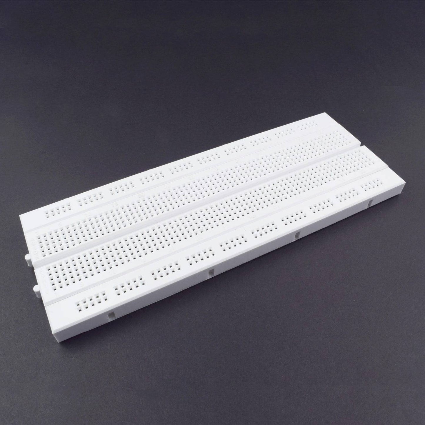
- Breadboard 840 points - 1
HARDWARE REQUIRED
- NE555 Timer IC - 1
- Transistor BC547 - 3
- Diode 1N4007 - 2
- LED - 2
- Resistor (R1&R2- 100K – 4 pcs , R3 - 1K – 2 pcS,R4 - 10K – 2pc , R5 & R6 - 4.7K – 4 pcs , R7&R8 - 1K – 4 pc
- Capacitor (C1 & C2 - 100nF, C3 - 470uF/16V) – 2 pieces each)
- Push Button - 2
- LDR - 2
- Piezo-Speaker - 1
- Battery 9v - 1
- battery snapper - 1
- Jumper Wire ( male to male) – 40 pieces
- Single Stand wire 2 meter – 1
- Breadboard 840 points - 1
SPECIFICATIONS
power Supply - 9v(From 9V battery)
PIN DESCRIPTION
555 Timer IC


Pin |
Name |
Purpose |
1 |
GND |
Ground reference voltage, low level (0 V) |
2 |
TRIG |
The OUT pin goes high and a timing interval starts when this input falls below 1/2 of CTRL voltage (which is typically 1/3 Vcc, CTRL being 2/3 Vcc by default if CTRL is left open). In other words, OUT is high as long as the trigger low. Output of the timer totally depends upon the amplitude of the external trigger voltage applied to this pin. |
3 |
OUT |
This output is driven to approximately 1.7 V below +Vcc, or to GND. |
4 |
RESET |
A timing interval may be reset by driving this input to GND, but the timing does not begin again until RESET rises above approximately 0.7 volts. Overrides TRIG which overrides threshold. |
5 |
CTRL |
Provides “control” access to the internal voltage divider (by default, 2/3 Vcc). |
6 |
THR |
The timing (OUT high) interval ends when the voltage at threshold is greater than that at CTRL (2/3 Vcc if CTRL is open). |
7 |
DIS |
Open collector output which may discharge a capacitor between intervals. In phase with output. |
8 |
Vcc |
Positive supply voltage, which is usually between 3 and 15 V depending on the variation. |

Led


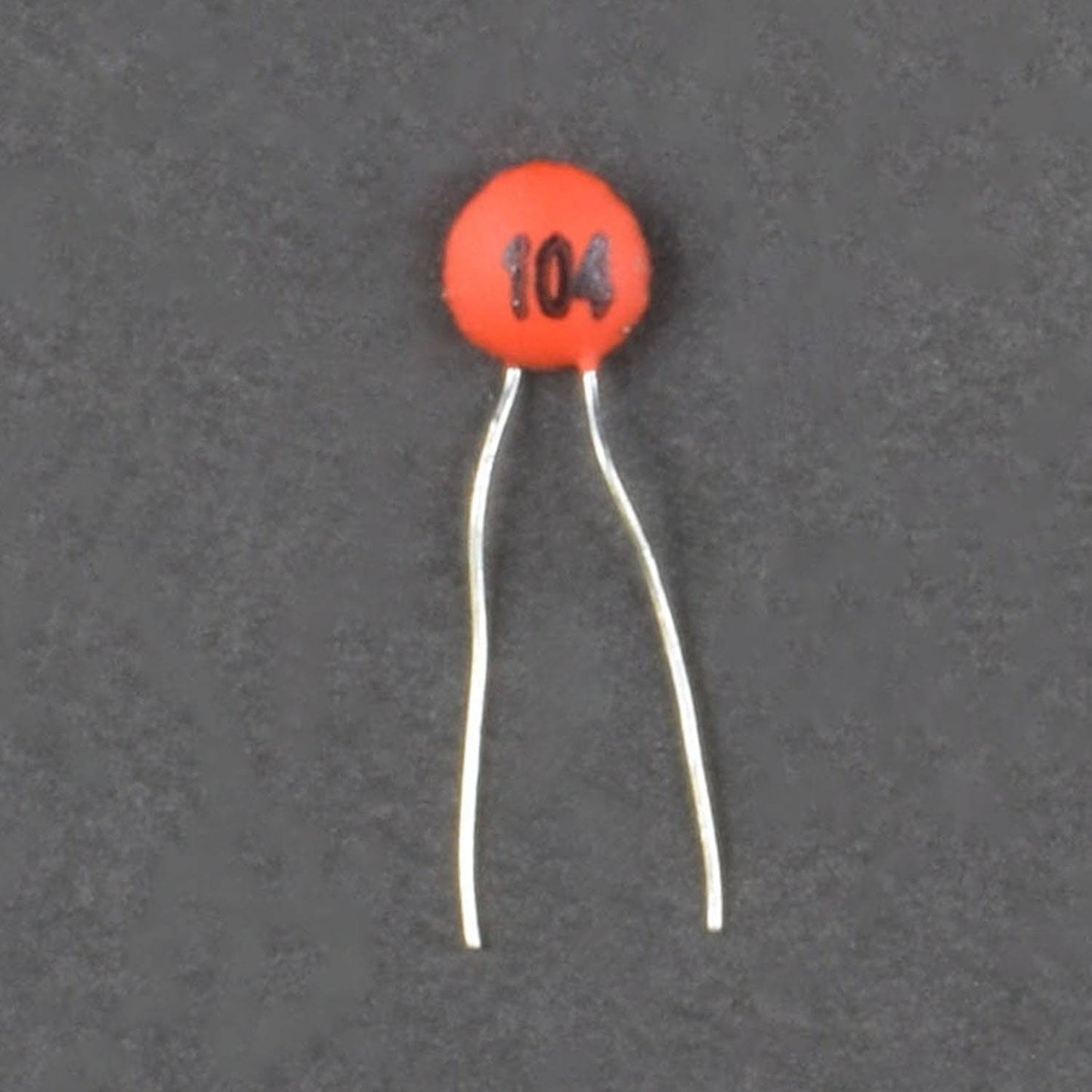
Capacitor


Diode


CIRCUIT CONNECTION


- 555 Timer IC connected to the Breadboard and Pin No. 1 is GND.
- Pin No. 1 to connected 100nF (104) capacitor and capacitor 2nd leg connected to the Pin No. 2.
- Pin No. 3 to connected 1K Resistor and Resistor 2nd leg connected to the BC547 Transistor (T2) Middle leg.
- BC547 Transistor (T2) 1st leg (E-right) is GND and 2nd leg connected to the LED negative leg and LED Positive leg connected to the 1K Resistor and Resistor 2nd leg connected to the positive supply.
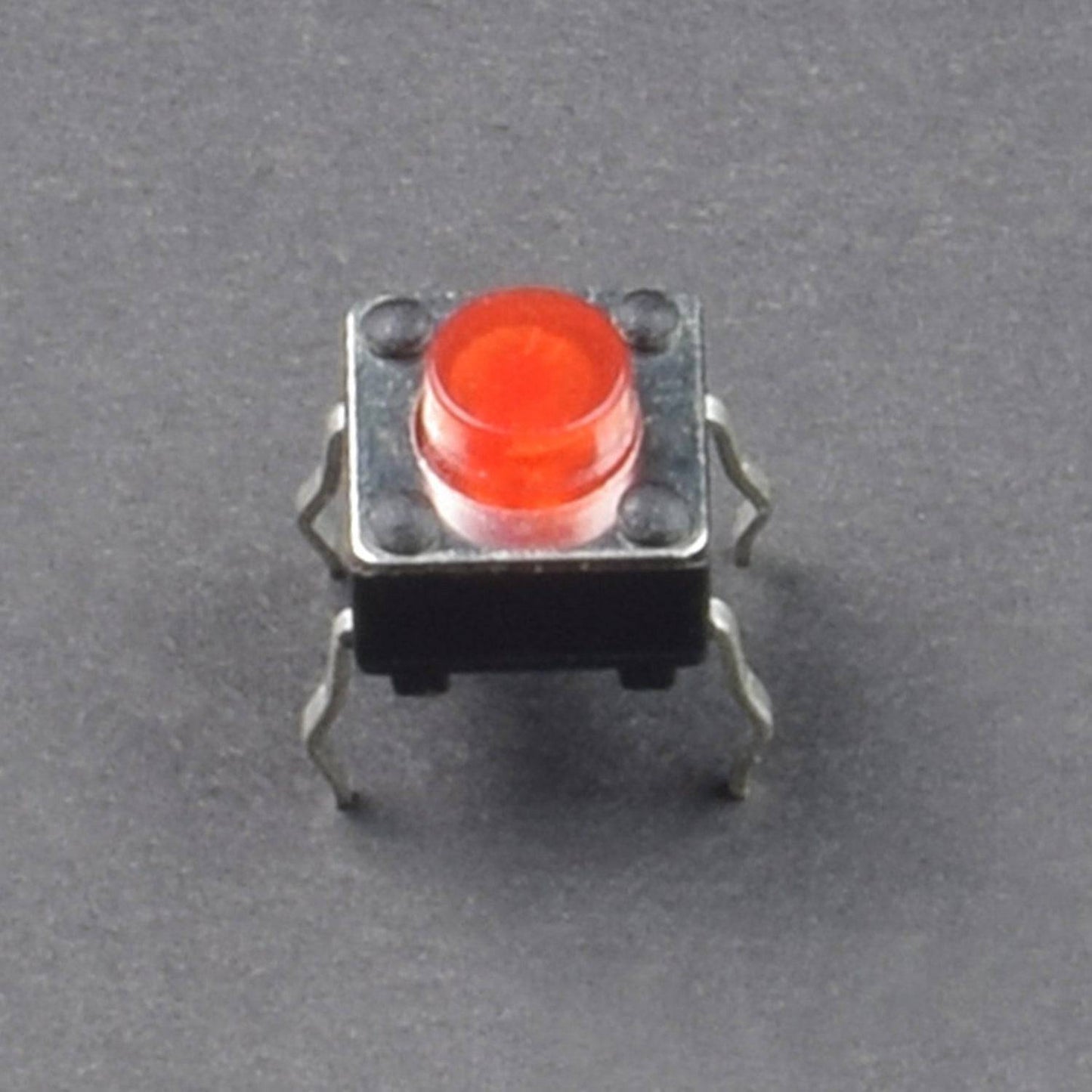
- Push Button 1st led is GND and 2nd leg connected to the positive supply.
- BC547 Transistor(T2) 2nd leg to connected Piezo Buzzer negative leg and Buzzer positive leg connected to the Push Button 2nd leg.
- 470uF capacitor positive leg connected to the positive supply and negative leg is GND.
- 555 Timer IC Pin No. 4 connected to the BC457 Transistor (T1) 2nd leg(C-left) and Transistor 1st leg (E-right) is GND.
- Transistor (T1) Middle leg to connected 1K Resistor and LDR, Resistor 2nd leg is GND and LDR 2nd leg connected to the positive supply.
- 555 Timer IC Pin No. 5 to connected 100nF (104) capacitor and capacitor 2nd leg connected to the positive supply.
- 555 Timer IC Pin No. 6 to connected 4.7K resistor and Resistor 2nd led connected Pin No. 7, Pin No. 7 to connected another 4.7K resistor and Resistor 2nd leg connected to the positive supply.
- 555 Timer IC Pin No. 8 connected to the positive supply.
- 100K Resistor to connected LED negative leg and LED positive leg to connected diode 1N4007 negative leg.
- 230v AC connected to the 100K resistor and diode positive leg.
- Breadboard connection positive to positive and negative to negative.
WORKING
This minuscule power failure alarm circuit is a power supply monitoring device that will set off a piezo-speaker when the ac mains supply cuts off. It is very helpful to indicate the loss of power supply to some power-critical instruments such as a life care device installed in a hospital. Alarm activation at the right time is helpful as it signals that there is a power outage and urgent action should take to recover the situation by providing an alternative power supply.
This is a 9V battery operated, low component count, and light weight circuit which can be safely connected to any AC230V outlet. At its heart is the famed little timer chip LM555 (IC1) configured as an astable multivibrator. Another important component is the “home-baked” opto-coupler (PC1). No bulky power transformer is used here, hence the circuit is “noise-free” (no electromagnetic interference).
Although a variety of opto-couplers are available in the market but it may so happen that you may not have one ready at hand when you get a spark and want to check the idea as soon as possible. Fortunately, it is easy to construct one at home using an LED and a phototransistor/photo resistor. Just take a small piece of common circuit board and solder the components as indicated here. Keep an eye on the spacing of the components; it should be as close as possible with a slight gap between them. In the prototype one 5mm white LED + 5mm LDR combination was used. After the construction, enclose the opt coupler in a suitable opaque tube, or cover the whole unit using short-length of heat shrink tube.
The circuit is straight forward. As stated, IC1 is here wired as a gated-astable producing an audio-frequency (AF) output (~1 KHz) to drive a standard ordinary/piezo-speaker. Switching of the astable is controlled by the power status detection circuitry built around PC1 and associated components. Switch S1 (SPST) is the system on/off switch, and LED2 (5mm Red) is an optional visual indicator.