


vendor-unknown
Make a Pattern with 16 Leds using HC595 shift Register interfacing with Arduino Uno - KT938
Make a Pattern with 16 Leds using HC595 shift Register interfacing with Arduino Uno - KT938
SKU:KT938
1000 in stock
Couldn't load pickup availability
- For Bulk Order Click Here
- Need Customer Support?
- Free Delivery Above 999/-
Note: In case you receive a damaged or faulty product, please return it in the original box with all foam and packaging. Returns will not be accepted if further damage occurs due to improper packing.
If you order a product that is currently in Preorder, and the price of that item increases in the future, you will be required to pay the difference in price.
For refund/return/replacement, call us at +91 95995 94520 or email us at support@rees52.com
Delivery Time
Delivery Time
- Delivery time with the Express Shipping option is 2-3 working days, and with the Standard Shipping option is 5-6 working days. It varies based on location, reliant on courier services.
- Delivery time if the order item is on Preorder Status is 15-20 working days.
COD (Cash on Delivery)
COD (Cash on Delivery)
- For COD you have to pay extra charges of Rs 350/- before the shipment. (We will share the company QR Code, UPI ID or Account details for the same)

KIT INCLUDES:
- Arduino Uno with USB Cable – 1
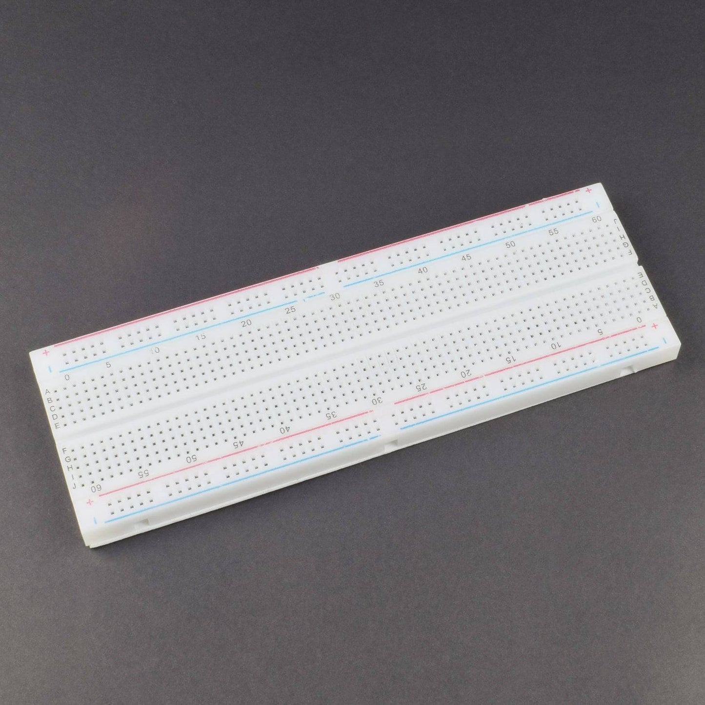
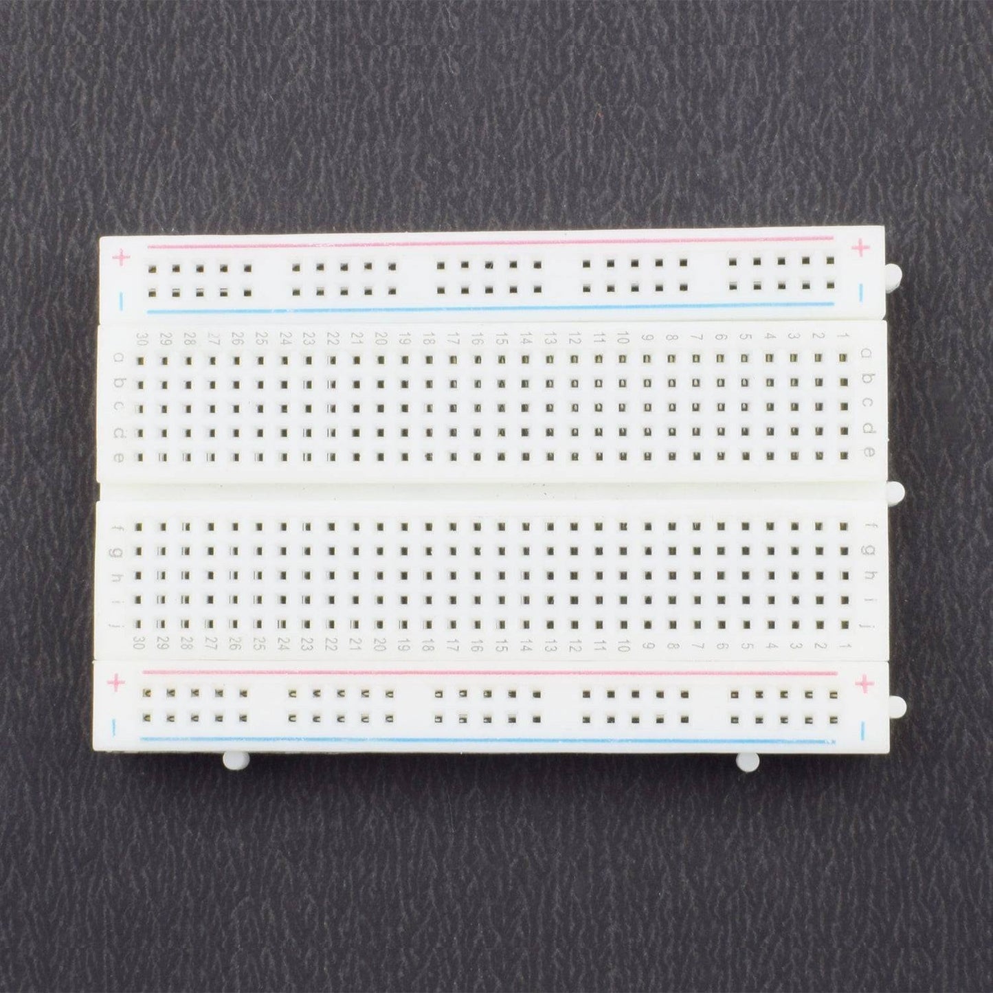
- Breadboard 840 points – 1
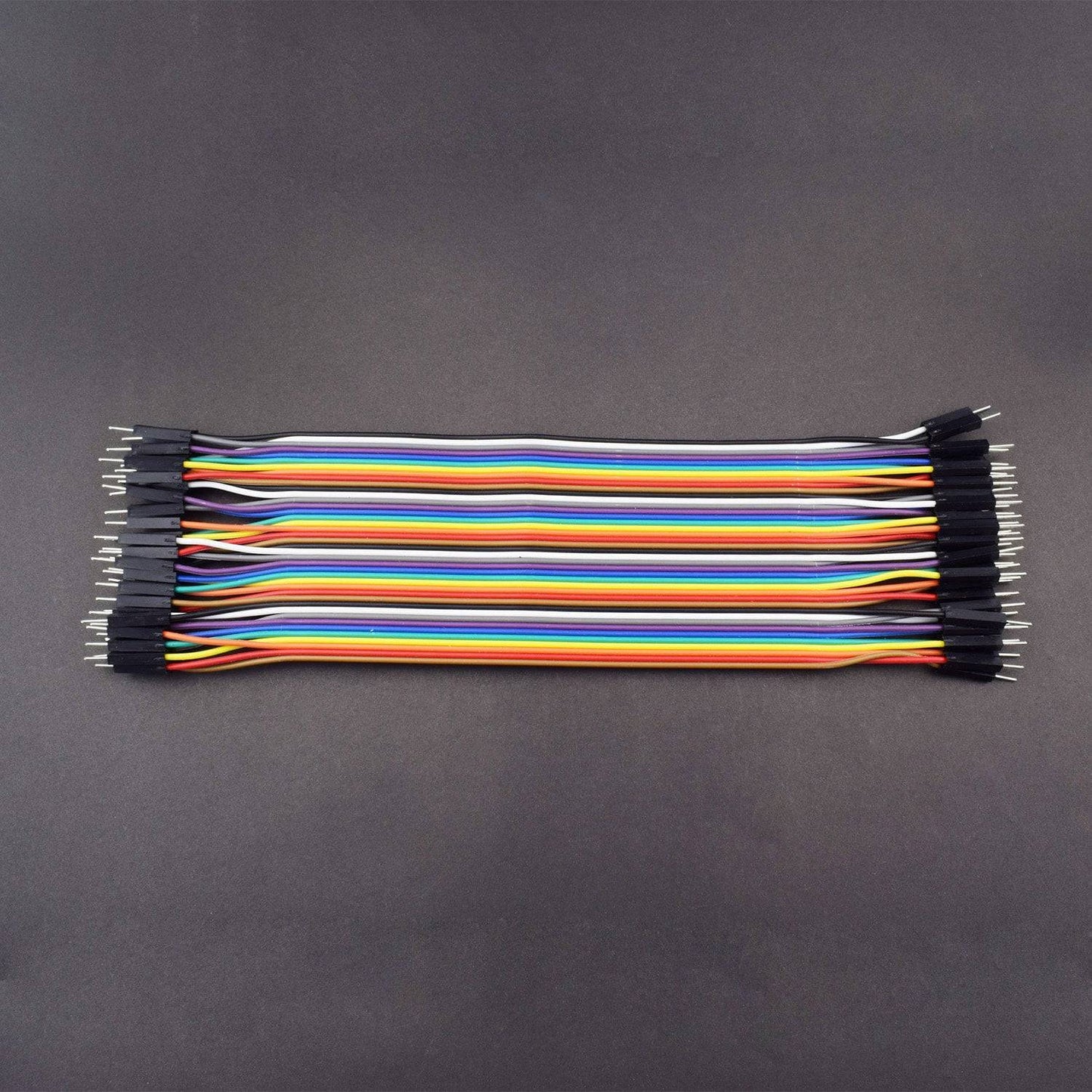
- Jumper wire (Male to male) – 40pcs
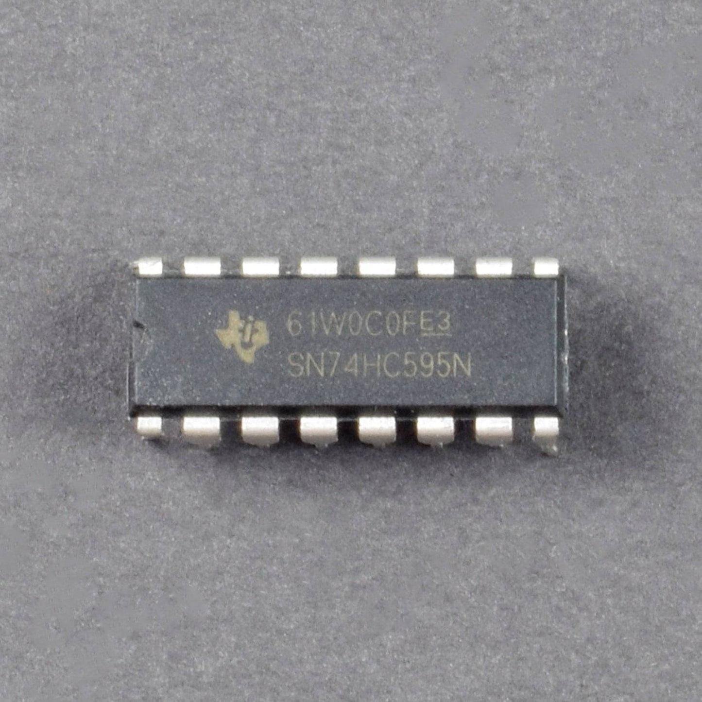
- Shift Register(SN74HC595N) – 2
- Breadboard 400 points – 1
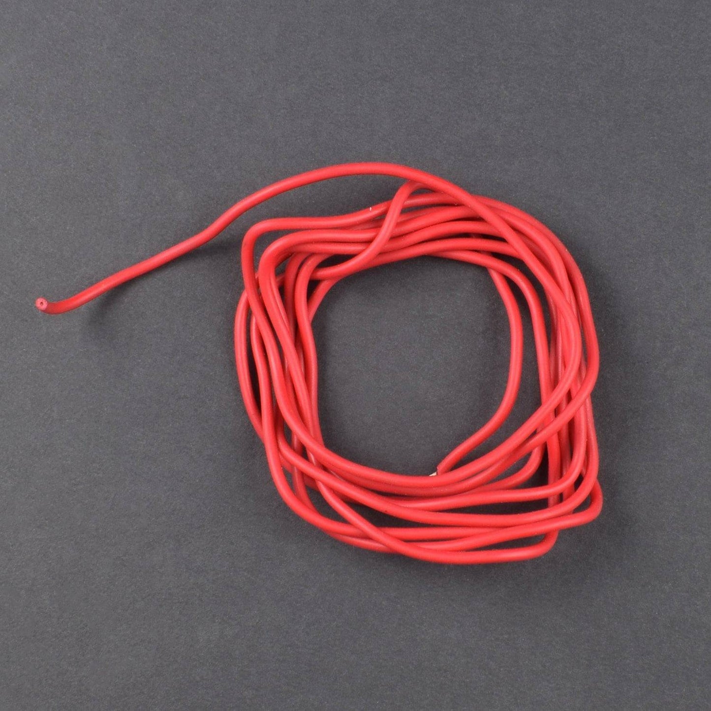
- Single stand wire 2mt- 1
- Potentiometer 10 k – 1
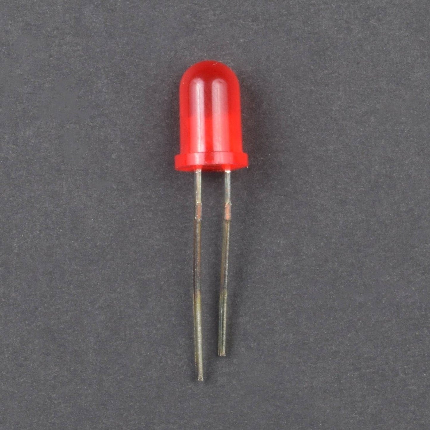
- Led – 16
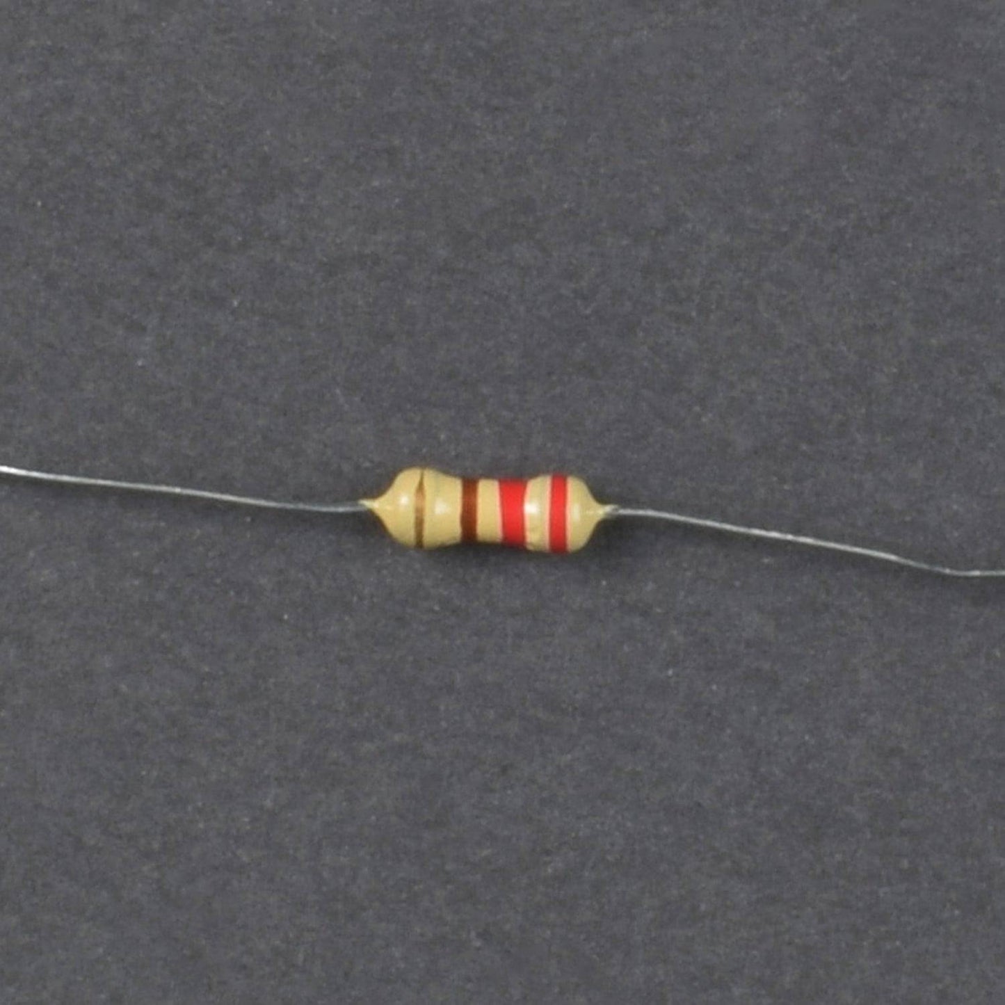
- Resistor 220 ohm – 16
HARDWARE REQUIRED
- Arduino Uno with USB Cable – 1
- Breadboard 840 points – 1
- Jumper wire (Male to male) – 40pcs
- Shift Register(SN74HC595N) – 2
- Breadboard 400 points – 1
- Single stand wire 2mt- 1
- Potentiometer 10 k – 1
- Led – 16
- Resistor 220 ohm – 16
SOFTWARE REQUIRED
Arduino IDE 1.8.5 (programmable platform for Arduino)
Click To Download :https://www.arduino.cc/en/Main/Software

TYPICAL APPLICATION
HC595 SHIFT REGISTER
- General Purpose Logic
- Serial to Parallel Data conversion
- Capture and hold data for extended periods of time.
- Allow simple serial bit streams from a microcontroller to control as many peripheral lines as needed.
- Wide array of products such as:
- Computer peripheralS
- Appliances
- Industrial control
SPECIFICATIONS
HC595 SHIFT REGISTER
- Wide Supply Voltage Range from 2.0V to 6.0V
- Sinks or sources 8mA at VCC = 4.5V
- CMOS low power consumption
- Schmitt Trigger Action at All Inputs
- Inputs accept up to 6.0V
- ESD Protection Tested per JESD 22
PIN DESCRIPTION
HC595 SHIFT REGISTER

10K POTENTIOMETER

LED

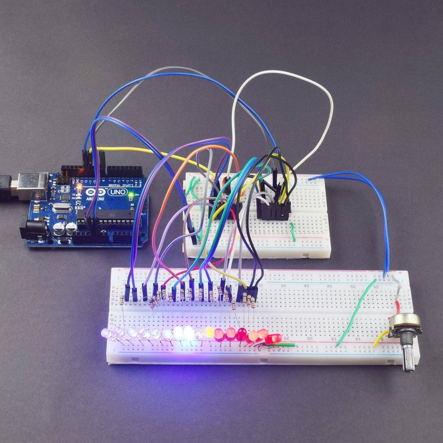
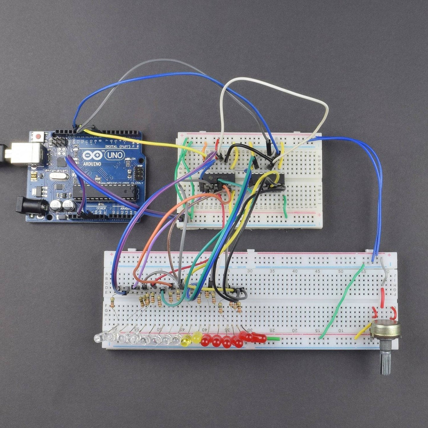
CIRCUIT DESCRIPTION
- Make the circuit (see above) and connect the first shift register as following:
-GND (pin 8) to ground
-Vcc (pin 16) to 5V
-OE (pin 13) to ground
-MR (pin 10) to 5V
-DS (pin 14) to Arduino pin 11
-SH_CP (pin 11) to Arduino pin 12
-ST_CP (pin 12) to Arduino pin 8
- Connect the second shift register exactly the same, but connect the DS (pin 14) to first register pin 9. After that connect pins: 1, 2, 3, 4, 5, 6, 7 and15 from both registers to LEDs. This connection makes all the pins always active and addressable, however when the Arduino is powered up some of the LEDs may be turned on. Solution for this is to connect MR (pin 10) and OE (pin 13) to Arduino directly, but it this way you have to sacrifice 2 Arduino pins.
- To add more shift registers connect them like the second register. Always connect MR and OE pins directly to Arduino and DS pin to previous register
- If you want to regulate the brightness of LEDs then connect potentiometer as shown in picture above to control resistance for all LEDs. However it is optional and you can get along without it.

CODE
Click to see the code and copy the link:
WORKING
Connect the Arduino uno and upload the Code given next .After uploading the code you will see the different pattern by glowing led which is controlled by potentiometer.