


vendor-unknown
Make a Panic Alarm using 555 Timer IC - KT960
Make a Panic Alarm using 555 Timer IC - KT960
SKU:KT960
999 in stock
Couldn't load pickup availability
- For Bulk Order Click Here
- Need Customer Support?
- Free Delivery Above 999/-
For refund/return/replacement, call us at +91 95995 94520 , +91 95991 22209 or mail us at support@rees52.com
Delivery Time
Delivery Time
- Delivery time with the Express Shipping option is 2-3 working days, and with the Standard Shipping option is 5-6 working days. It varies based on location, reliant on courier services.
- Delivery time if the order item is on Preorder Status is 15-20 working days.
COD (Cash on Delivery)
COD (Cash on Delivery)
- For COD you have to pay extra charges of Rs 350/- before the shipment. (We will share the company QR Code, UPI ID or Account details for the same)
KIT INCLUDES:
- Breadboard 840 points -1
- NE555 Timer Ic -1
- Transistor BC547 – 2
- 9v Battery -1
- battery snapper – 1
- Led – 2
- Resistors (10kὨ – 3; 220Ὠ - 2;OR 1KὨ - 2)
- Ceramic capacitor(0.01uF) – 2
- Push button – 2
- Buzzer – 1
Introduction
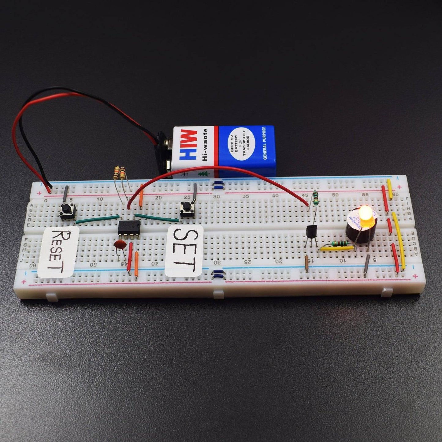
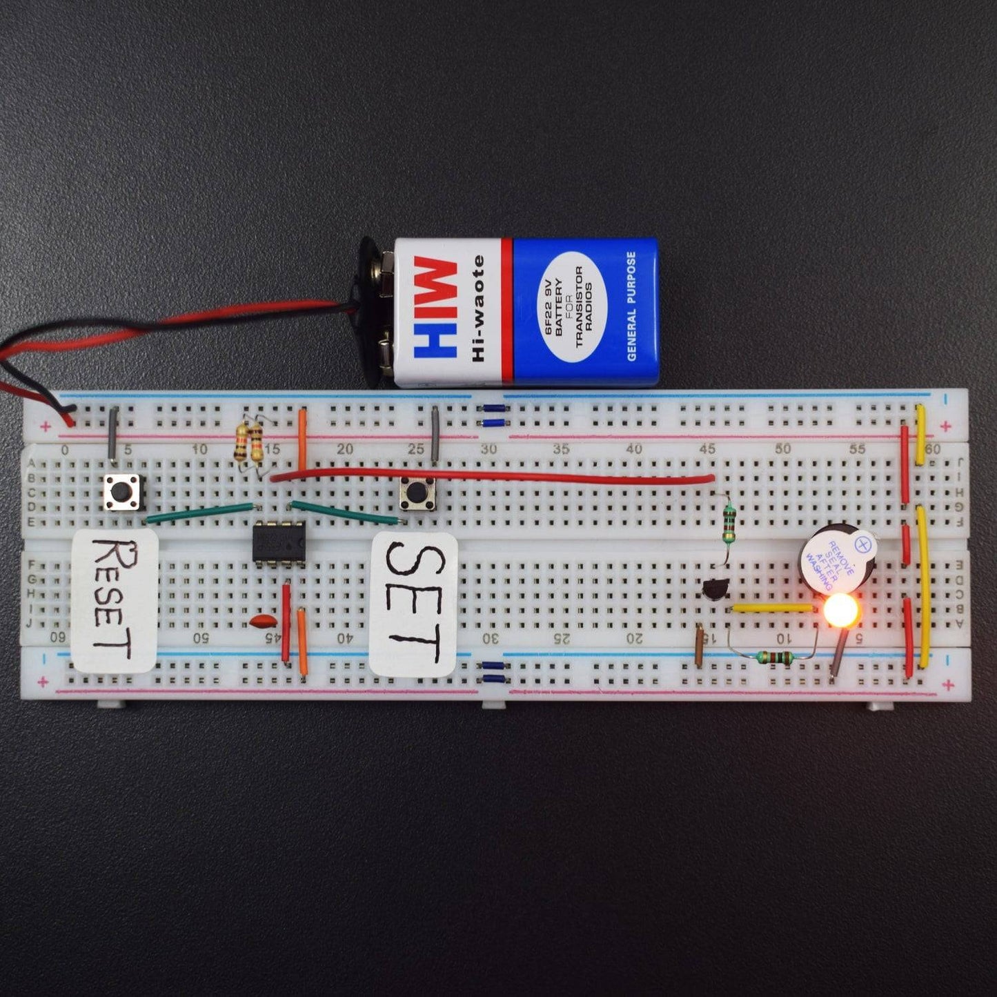
In this project, we will make a Panic Alarm using 555 Timer IC. This Panic Alarm is used to send an emergency signal just by pushing a single button. After a few time alarm will be off and if you reset the button alarm will stop.
HARDWARE REQUIRED
- Breadboard 840 points -1
- NE555 Timer Ic -1
- Transistor BC547 – 2
- 9v Battery -1
- battery snapper – 1
- Led – 2
- Resistors (10kὨ – 3; 220Ὠ - 2; OR 1KὨ - 2)
- Ceramic capacitor(0.01uF) – 2
- Push button – 2
- Buzzer – 1
PIN DESCRIPTION
LED

555 TIMER IC


Pin |
Name |
Purpose |
1 |
GND |
Ground reference voltage, low level (0 V) |
2 |
TRIG |
The OUT pin goes high and a timing interval starts when this input falls below 1/2 of CTRL voltage (which is typically 1/3 Vcc, CTRL being 2/3 Vcc by default if CTRL is left open). In other words, OUT is high as long as the trigger low. Output of the timer totally depends upon the amplitude of the external trigger voltage applied to this pin. |
3 |
OUT |
This output is driven to approximately 1.7 V below +Vcc, or to GND. |
4 |
RESET |
A timing interval may be reset by driving this input to GND, but the timing does not begin again until RESET rises above approximately 0.7 volts. Overrides TRIG which overrides threshold. |
5 |
CTRL |
Provides “control” access to the internal voltage divider (by default, 2/3 Vcc). |
6 |
THR |
The timing (OUT high) interval ends when the voltage at threshold is greater than that at CTRL (2/3 Vcc if CTRL is open). |
7 |
DIS |
Open collector output which may discharge a capacitor between intervals. In phase with output. |
8 |
Vcc |
Positive supply voltage, which is usually between 3 and 15 V depending on the variation. |
TRANSISTOR
![]()
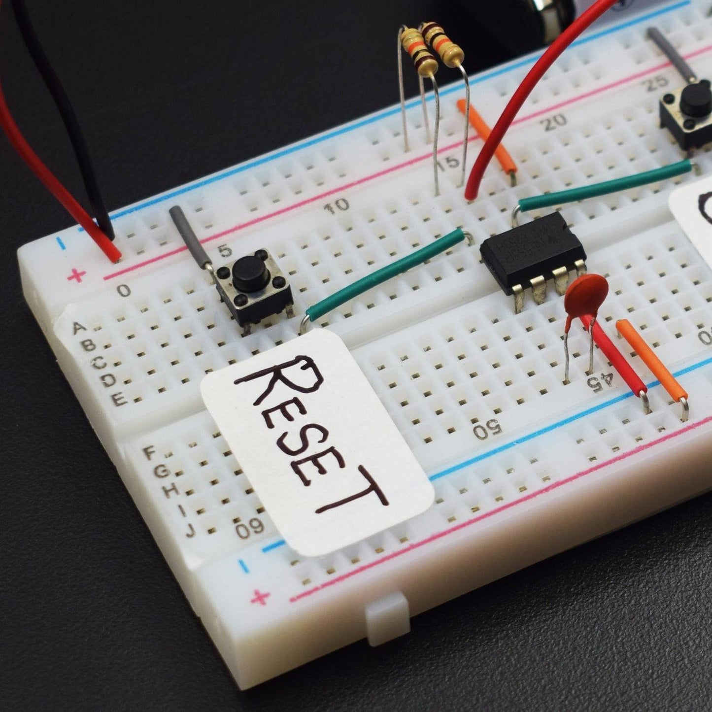
CIRCUIT DESCRIPTION


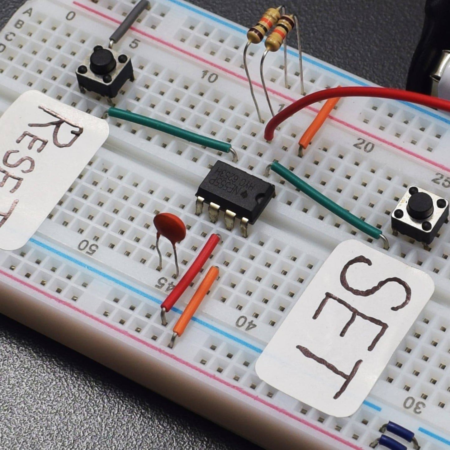
- Attach 555 Timer IC with the breadboard.
- Connect Pin 1 of IC to the GND rail on Breadboard.
- Connect 10K resistor to the pin 3 & 4 to the 555 Timer IC and the other terminal of resistors to the GND rail on breadboard.
- Connect both leg of 0.01 µf ceramic capacitor to both 5 and 6 pins of 555 Timer IC.
- Connect 7th pin of 555 Timer IC to GND rail and 8th pin to the positive rail on breadboard.
- Attach two Tactile switches to the breadboard.
- Connect one internally connected side of tactile switch to the GND similarly do for the second switch.
- Connect 1st tactile switch to the Pin2 of 555 Timer IC.
- Connect 2nd Tactile switch to the pin 4 of 555 Timer IC.
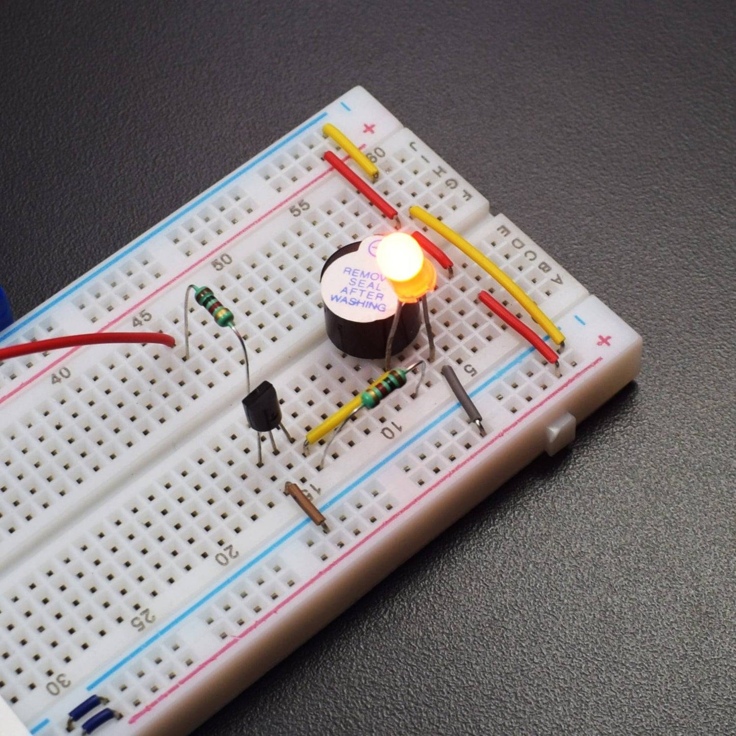
- Attach Buzzer on the breadboard.
- Attach the led in the same column of the buzzer
- Connect the positive terminal of led and buzzer to the positive rail on breadboard.
- Attach the BC547 transistor to the breadboard
- Connect base (middle) pin of transistor to the 3rd pin of 555 Timer IC via 1Kohm Resistor.
- Now connect Negative terminal of Led and buzzer to the Collector pin of BC547 transistor via 1K resistor.
- Connect Emitter pin of Transistor to the GND rail on the breadboard.
WORKING
When the SET button is pressed LED gets turned on and buzzer starts beeping,
When RESET button is pressed the LED and buzzer goes OFF.
When you press the reset button, led and buzzer goes off. This is happened because circuit is in disable mode.
Whenever you provide the power supply, circuit will operate in astable mode when IC is enabled
d. This IC is in 555 timer IC Is given a high voltage.