
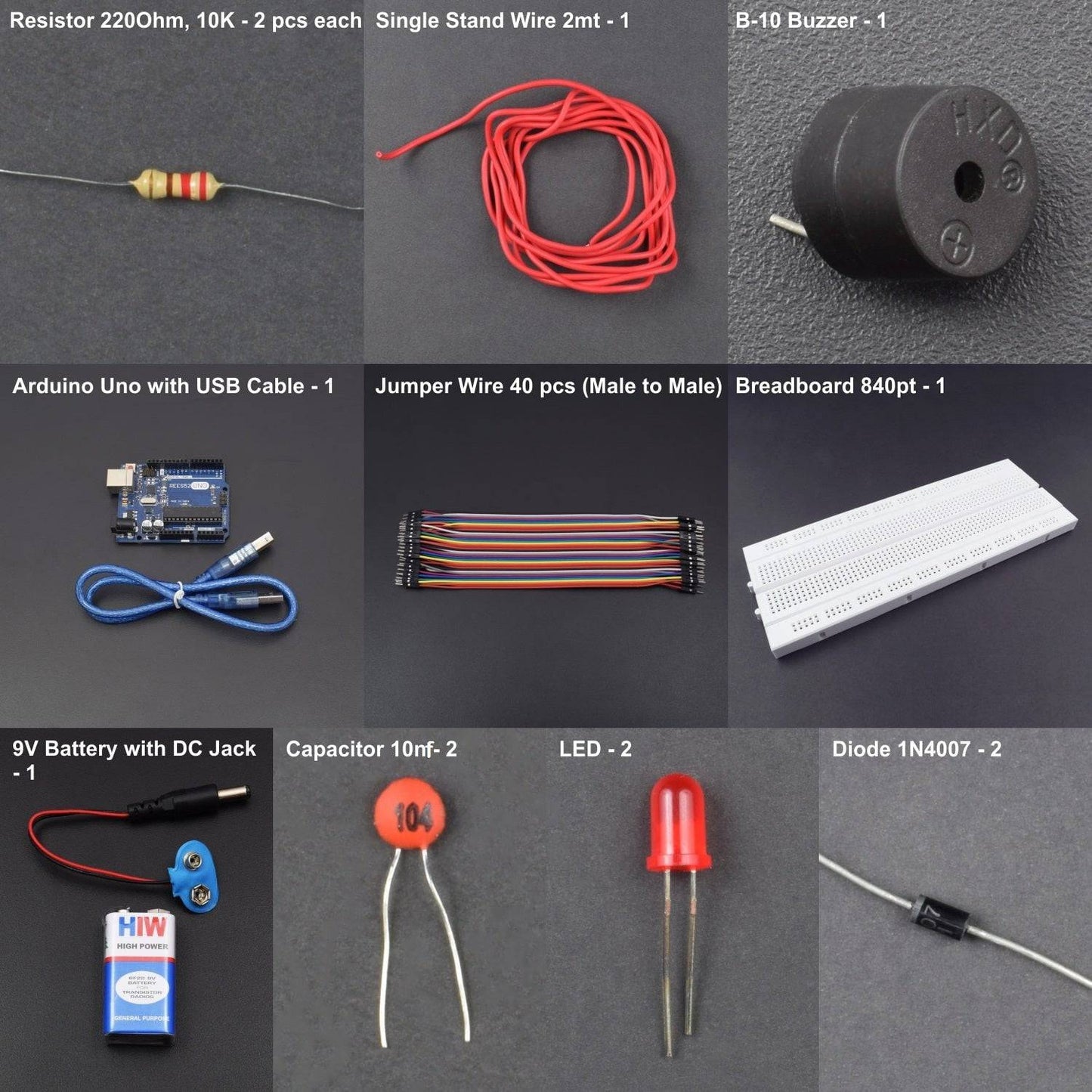
KIT INCLUDES:
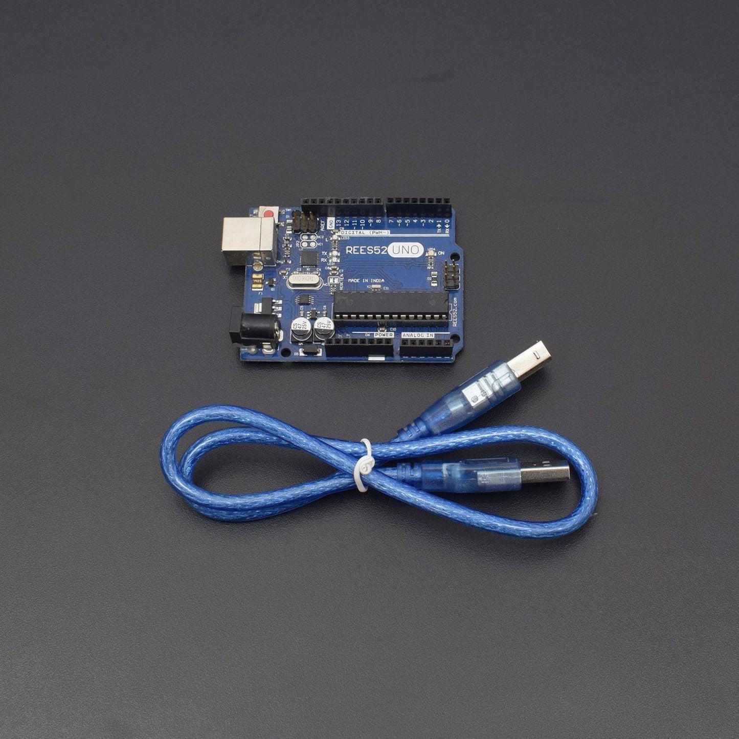
- Arduino uno with USB Cable -1
- Coil (not included in kit)- 1
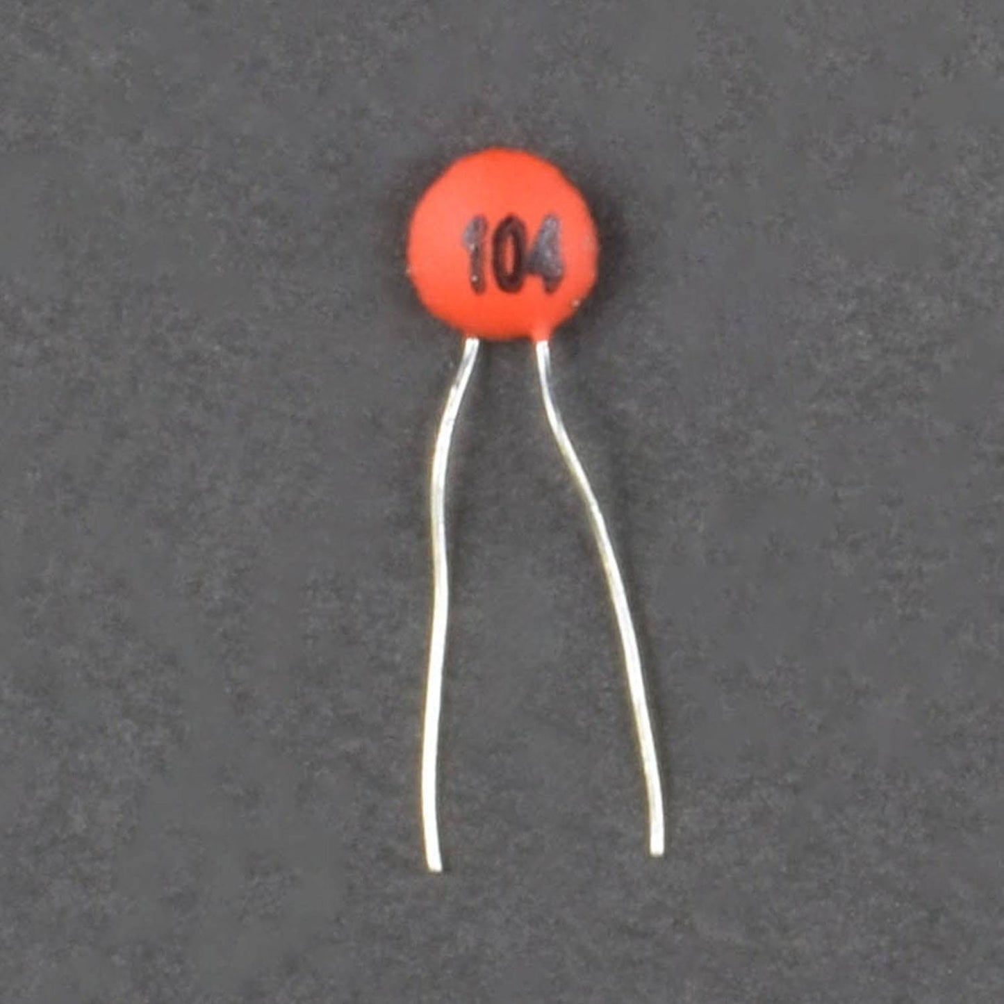
- 10nF capacitor - 2
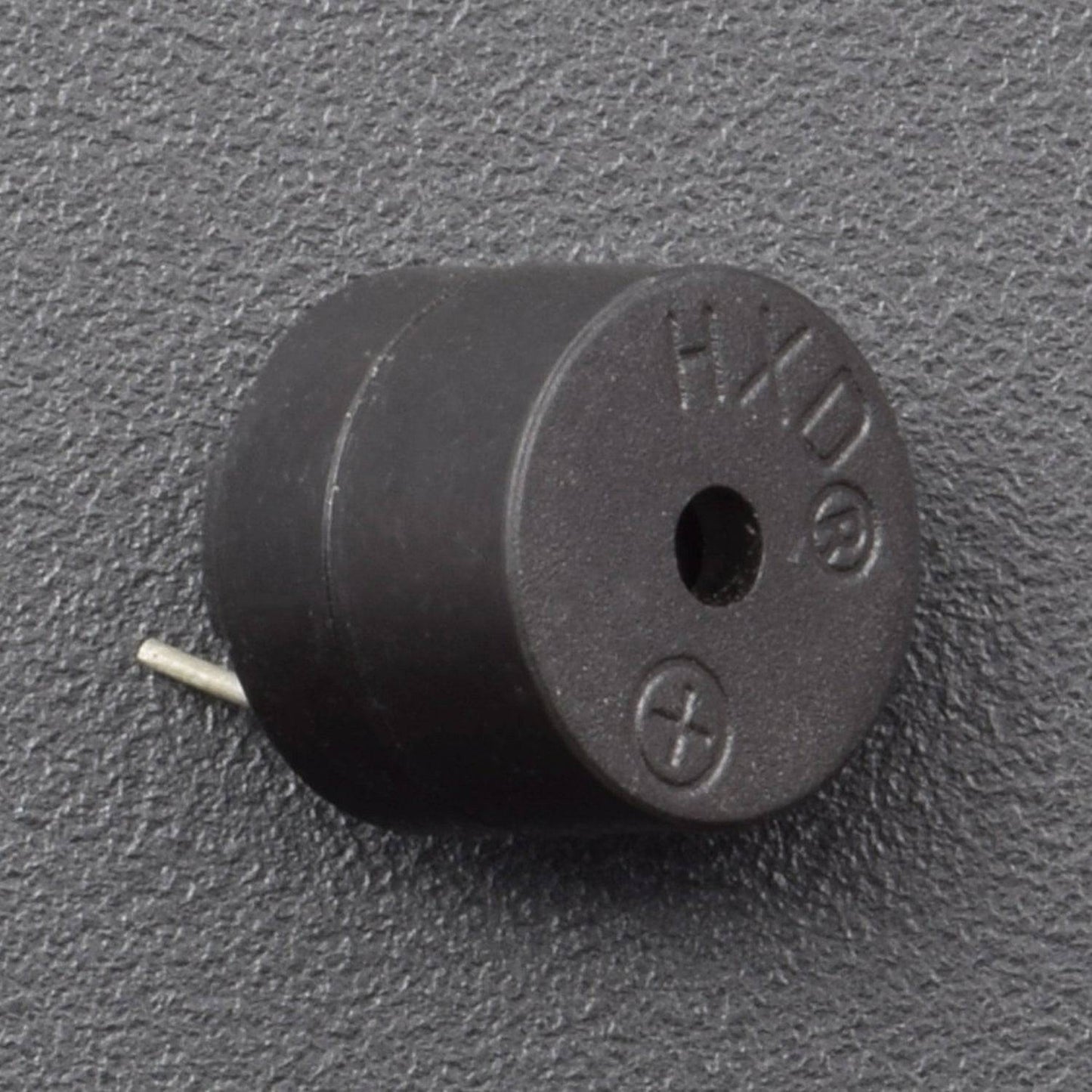
- Buzzer B10 – 1
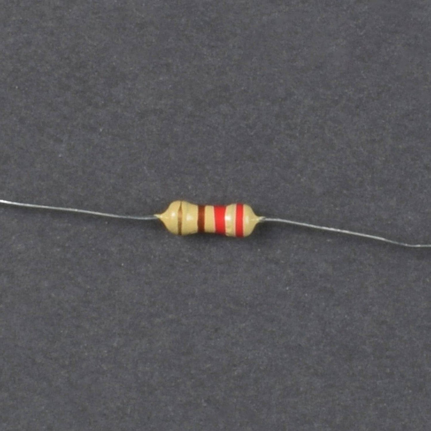
- Resistor(10k, 220 ohm) – 2 pieces each
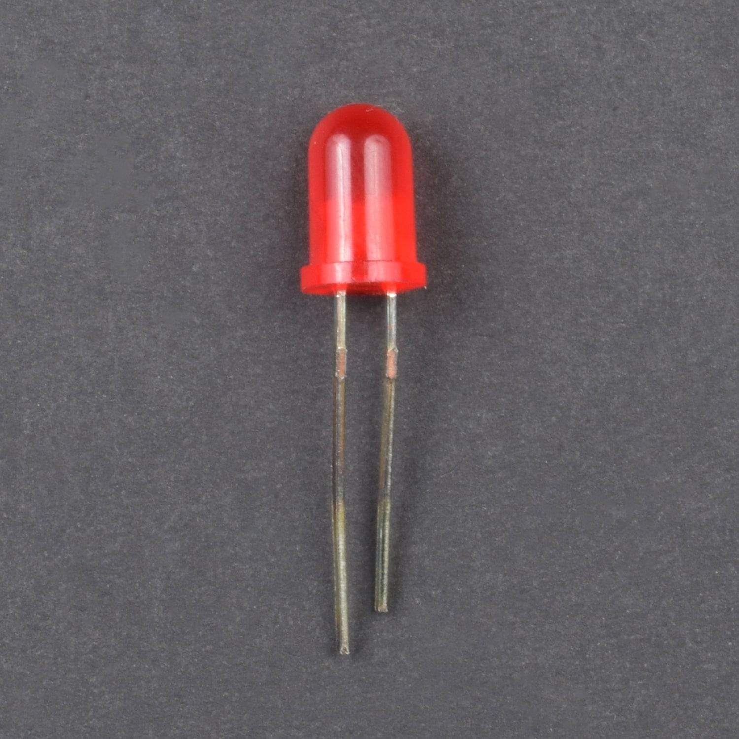
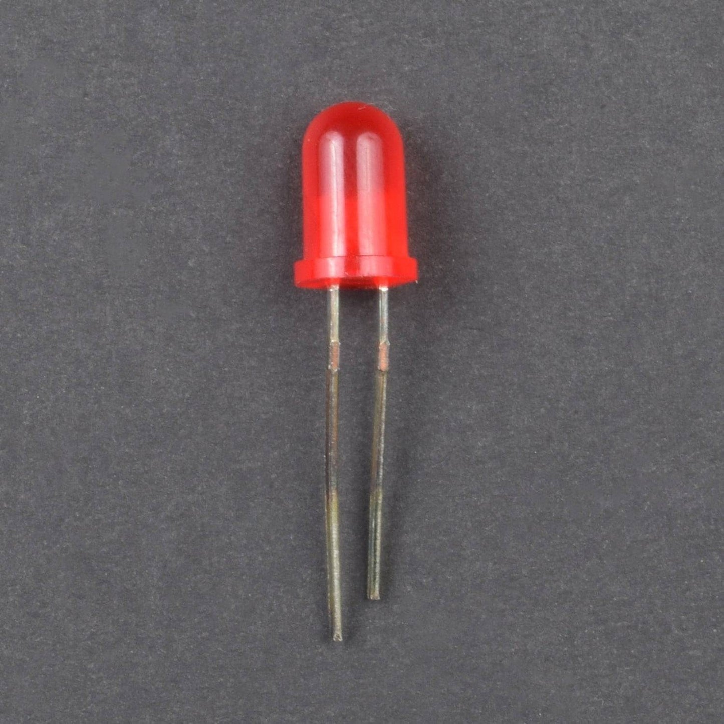
- 5mm LED (red) - 2
- 1N4007 diode - 2
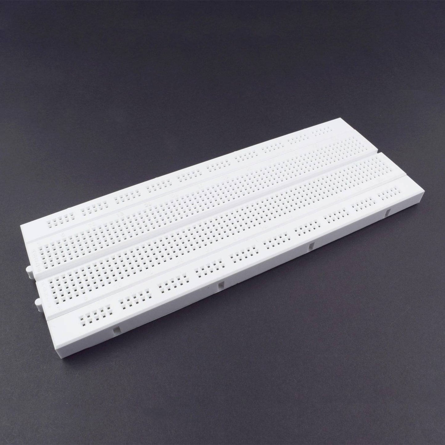
- Breadboard 840 points – 1
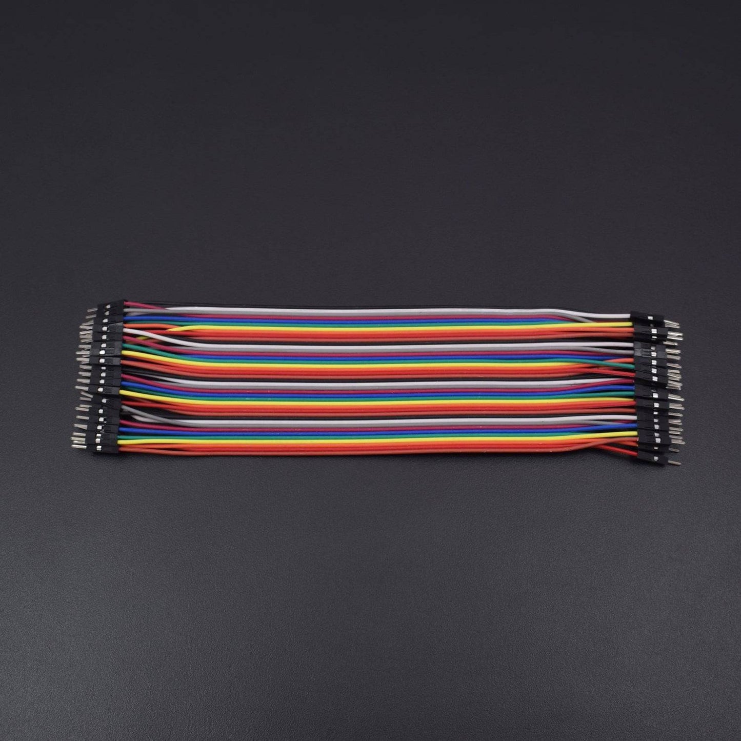
- Jumper wire (Male to male) – 40 pieces
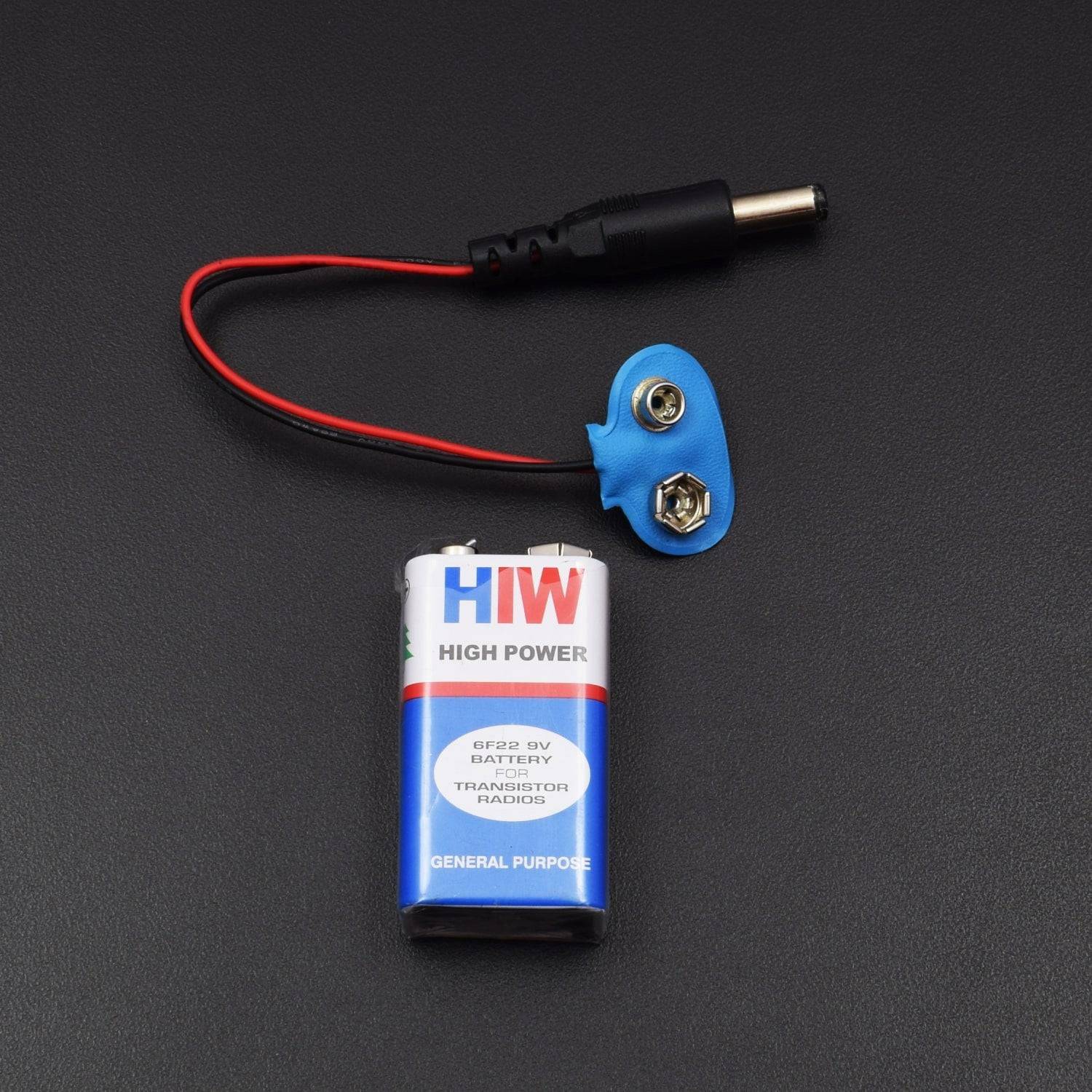
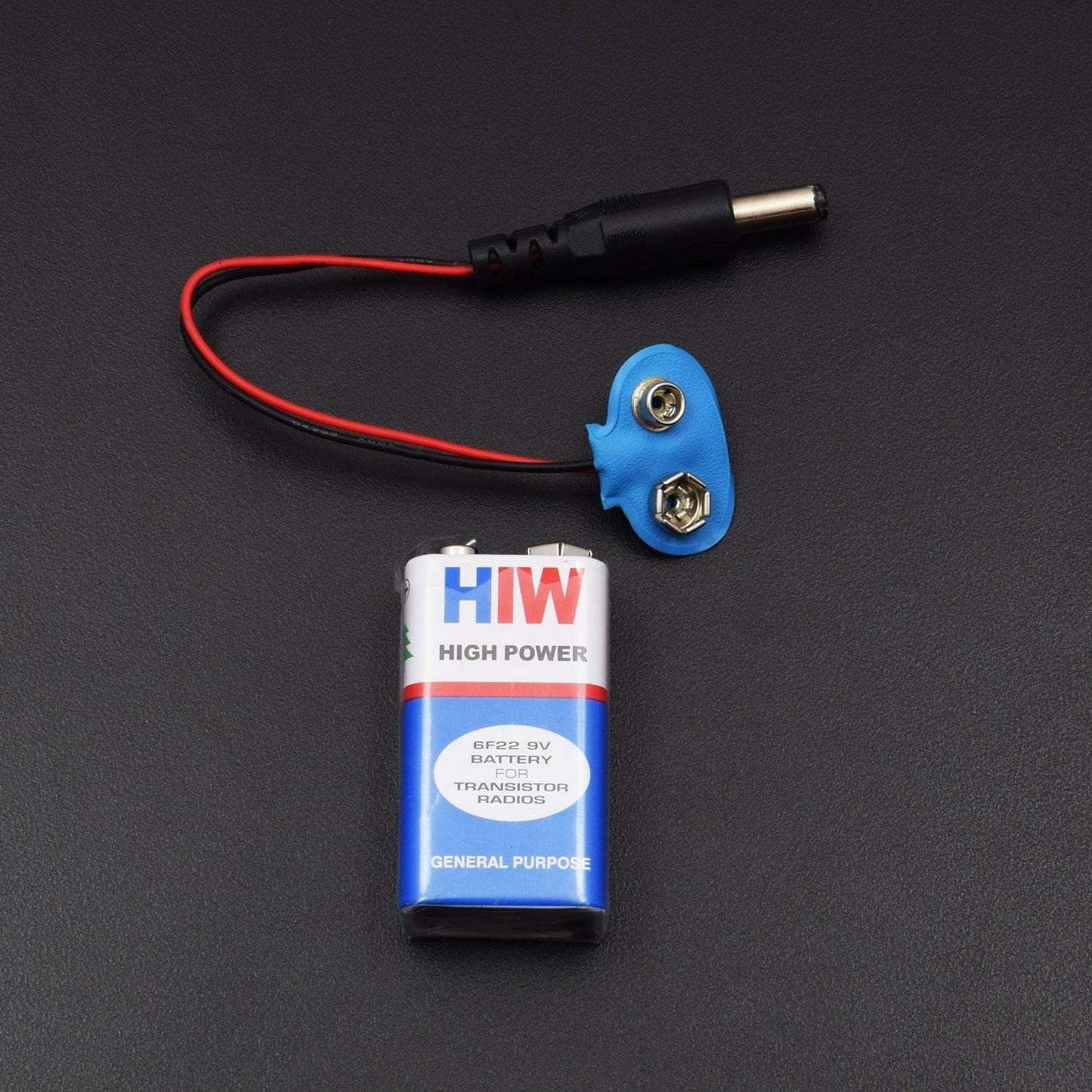
- 9v Battery with Dc jack – 1
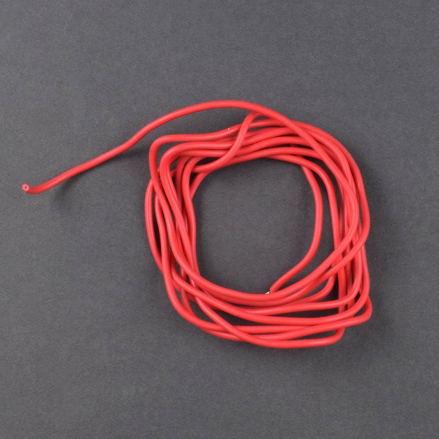
- Single stand wire 2mt - 1
HARDWARE REQUIRED
- Arduino uno with USB Cable -1
- Coil (not included in kit)- 1
- 10nF capacitor - 2
- Buzzer B10 – 1
- Resistor(10k, 220 ohm) – 2 pieces each
- 5mm LED (red) - 2
- 1N4007 diode - 2
- Breadboard 840 points – 1
- Jumper wire (Male to male) – 40 pieces
- 9v Battery with Dc jack – 1
- Single stand wire 2mt - 1
SOFTWARE REQUIRED
Arduino IDE 1.8.5 (programmable platform for Arduino)
Click To Download: https://www.arduino.cc/en/Main/Software
WORKING PRINCIPLE
Whenever some current passes through the coil, it generates a magnetic field around it. And the change in the magnetic field generates an electric field. Now according to Faraday's law, because of this Electric field, a voltage develops across the coil which opposes the change in magnetic field and that’s how Coil develops the Inductance, means the generated voltage opposes the increase in the current. The unit of Inductance is Henry and formula to measure the Inductance is:
L = (μο * N2 * A) / l
Where,
L- Inductance in Henry’s
μο- Permeability, its 4π*10-7 for Air
N- Number of turns
A- Inner Core Area (πr2) in m2
l- Length of the Coil in meters
When any metal comes near to the coil then coil changes its inductance. This change in inductance depends upon the metal type. It's decreases for non-magnetic metal and increases for ferromagnetic materials like iron.
Depending on the core of the coil, inductance value changes drastically. In the figure below you can see the air-cored inductors, in these inductors, there will be no solid core. They are basically coils left in the air. The medium of flow of magnetic field generated by the inductor is nothing or air. These inductors have inductances of very less value.
These inductors are used when the need for values of few microHenry. For values greater than few milli Henry these are not a suitable one. In below figure you can see an inductor with ferrite core. These Ferrite Core inductor has very large inductance value.
Remember the coil wound here is an air cored one, so when a metal piece is brought near the coil, the metal piece acts as a core for the air cored inductor. By this metal acting as a core, the inductance of the coil changes or increases considerably. With this sudden increase in inductance of coil the overall reactance or impedance of the LC circuit changes by a considerable amount when compared without the metal piece.
So here in this Arduino Metal Detector Project, we have to find inductance of the coil to detect metals. So to do this we have used LR circuit (Resistor-Inductor Circuit) that we already mentioned. Here in this circuit, we have used a coil having around 20 turns or winding with a 10cm diameter. We have used an empty tape roll and wind the wire around it to make the coil.
CIRCUIT CONNECTION

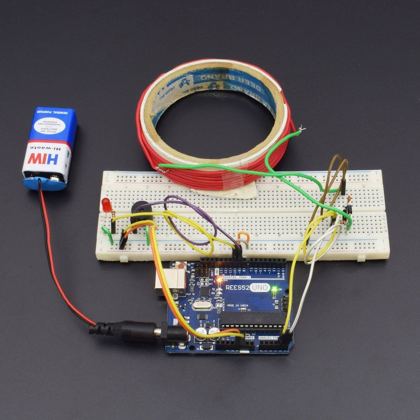
We have used an Arduino Nano for controlling whole this Metal Detector Project. A LED and Buzzer are used as metal detection indicator. A Coil and capacitor are used for detection of metals. A signal diode is also used or reduce the voltage. And a resistor for limiting the current to the Arduino pin.

CODE
WORKING
Working on this Arduino Metal Detector is the bit tricky. Here we provide the block wave or pulse, generated by Arduino, to the LR high pass filter. Due to this, short spikes will be generated by the coil in every transition. The pulse length of the generated spikes is proportional to the inductance of the coil. So with the help of these Spike pulses, we can measure the inductance of Coil. But here it is difficult to measure inductance precisely with that spikes because that spikes are of very short duration (approx. 0.5 microseconds) and that is very difficult to be measured by Arduino.
So instead of this, we used a capacitor which is charged by the rising pulse or spike. And it required few pulses to charge the capacitor to the point where its voltage can be read by Arduino analogue pin A5. Then Arduino read the voltage of this capacitor by using ADC. After reading voltage, capacitor quickly discharged by making capPin pin as output and setting it to low. This whole process takes around 200 microseconds to complete. For better result, we repeat measurement and took an average of the results. That’s how we can measure the approximate inductance of Coil. After getting the result we transfer the results to the LED and buzzer to detect the presence of metal. Check the Complete code given at the end of this Article to understand the working.
Complete Arduino code is given at the end of this Article. In programming part of this project, we have used two Arduino pins, one for generating block waves to be fed in Coil and second analog pin to read capacitor voltage. Other than these two pins, we have used two more Arduino pins for connecting LED and buzzer.


