


vendor-unknown
Make a lie Detector interfacing with Arduino Nano - KT852
Make a lie Detector interfacing with Arduino Nano - KT852
SKU:KT852
997 in stock
Couldn't load pickup availability
- For Bulk Order Click Here
- Need Customer Support?
- Free Delivery Above 999/-
Note: In case you receive a damaged or faulty product, please return it in the original box with all foam and packaging. Returns will not be accepted if further damage occurs due to improper packing.
If you order a product that is currently in Preorder, and the price of that item increases in the future, you will be required to pay the difference in price.
For refund/return/replacement, call us at +91 95995 94520 or email us at support@rees52.com
Delivery Time
Delivery Time
- Delivery time with the Express Shipping option is 2-3 working days, and with the Standard Shipping option is 5-6 working days. It varies based on location, reliant on courier services.
- Delivery time if the order item is on Preorder Status is 15-20 working days.
COD (Cash on Delivery)
COD (Cash on Delivery)
- For COD you have to pay extra charges of Rs 350/- before the shipment. (We will share the company QR Code, UPI ID or Account details for the same)

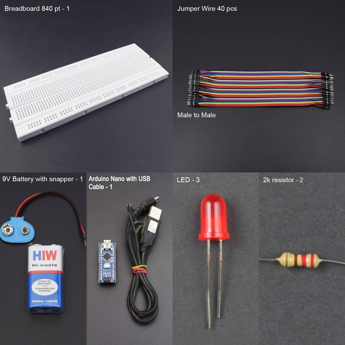
KIT INCLUDES:
- Arduino Nano - 1
- USB Cable - 1
- Breadboard 840 points - 1
- led -3
- 2k resistor - 2
- Jumper wires male to male – 40 pieces
- 9V Battery - 1
- Snapper - 1
HARDWARE REQUIRED
- Arduino Nano - 1
- USB Cable - 1
- Breadboard 840 points - 1
- led -3
- 2k resistor - 2
- Jumper wires male to male – 40 pieces
- 9V Battery - 1
- Snapper - 1
SOFTWARE REQUIRED
Arduino IDE 1.8.5 (programmable platform for Arduino)
Click To Download :https://www.arduino.cc/en/Main/Software


SPECIFICATIONS
Arduino Nano
- Microcontroller: Atmel ATmega168 or ATmega328
- Operating Voltage(logic level): 5 V
- Input Voltage(recommended): 7-12 V
- Input Voltage(limits): 6-20 V
- Digital I/O Pins: 14 (of which 6 provide PWM output)
- Analog Input Pins: 8
- DC Current per I/O Pin: 40 mA
- Flash Memory: 16 KB (ATmega168) or 32 KB (ATmega328) of which 2 KB used by bootloader
- SRAM: 1 KB (ATmega168) or 2 KB (ATmega328)
- EEPROM: 512 bytes (ATmega168) or 1 KB (ATmega328)
- Clock Speed: 16 MHz
LED
- It is exceptionally bright with a wide beam angle, so they’re suitable for use in illuminations, headlamps, spotlights, car lighting and models.
- The 5mm LED can be used anywhere where you need low power, high-intensity reliable lighting or indication.
- Voltage: 3.2V to 3.4V
- Current: 20 mA
- Typically Recommended Voltage: 3.2V
PIN DESCRIPTION
Arduino nano

.jpg)
LED


CIRCUIT DESCRIPTION

- Connect a piece of cable to Arduino Nano Analog Pin 0.
- Connect the 2k resistor to GND and the extended analog pin A0 of the Arduino Nano.
- Connect a piece of cable to Arduino 5V Pin.
- Connect the anode (+ve/long leg) of the green led to pin 2 and the cathode (-ve/short leg) to GND of Arduino Nano.
- Connect the anode (+ve/long leg) of the orange led to pin 3 and the cathode (-ve/short leg) to GND of Arduino Nano.
- Connect the anode (+ve/long leg) of the red led to pin 4 and the cathode (-ve/short leg) to GND of Arduino Nano.
CODE
Click to see code here: https://drive.google.com/open?id=1JmYqbpbuHj8a2a-JS7hNpp6uMzrQs6To
WORKING AND OUTPUT
Welcome to the Arduino based Lie Detector which consists of Arduino Nano, LED’s and resistor. It must be made sure that connections are made in an appropriate manner as given in circuit connection.
Here’s the basic functionality for Lie Detector. Our skin is amazing! It provides a medium for us to experience the sense of touch, it keeps infections out and keeps Innards in but I bet you didn't know that our skin changes conductivity depending on many different things.
Our mood! It called Electro dermal activity (EDA). The basics are that our skin changes its conductivity depending on "How we feel".
We start by connect our Arduino to the subject and then connect the Arduino & we can see the output on serial plotter or monitor. We have to start by asking the subject some easy questions we know they will answer truthfully like "what is your name" and "where do you live" to get a baseline and from there we can start asking questions that they may lie about, if they do they would probably feel nervous and then we can see the visual change.


