


vendor-unknown
Make a Laser security system using 555 Timer IC and LM358 IC - KT949
Make a Laser security system using 555 Timer IC and LM358 IC - KT949
SKU:KT949
1000 in stock
Couldn't load pickup availability
- For Bulk Order Click Here
- Need Customer Support?
- Free Delivery Above 999/-
Note: In case you receive a damaged or faulty product, please return it in the original box with all foam and packaging. Returns will not be accepted if further damage occurs due to improper packing.
For refund/return/replacement, call us at +91 95995 94520 or email us at support@rees52.com
Delivery Time
Delivery Time
- Delivery time with the Express Shipping option is 2-3 working days, and with the Standard Shipping option is 5-6 working days. It varies based on location, reliant on courier services.
- Delivery time if the order item is on Preorder Status is 15-20 working days.
COD (Cash on Delivery)
COD (Cash on Delivery)
- For COD you have to pay extra charges of Rs 350/- before the shipment. (We will share the company QR Code, UPI ID or Account details for the same)


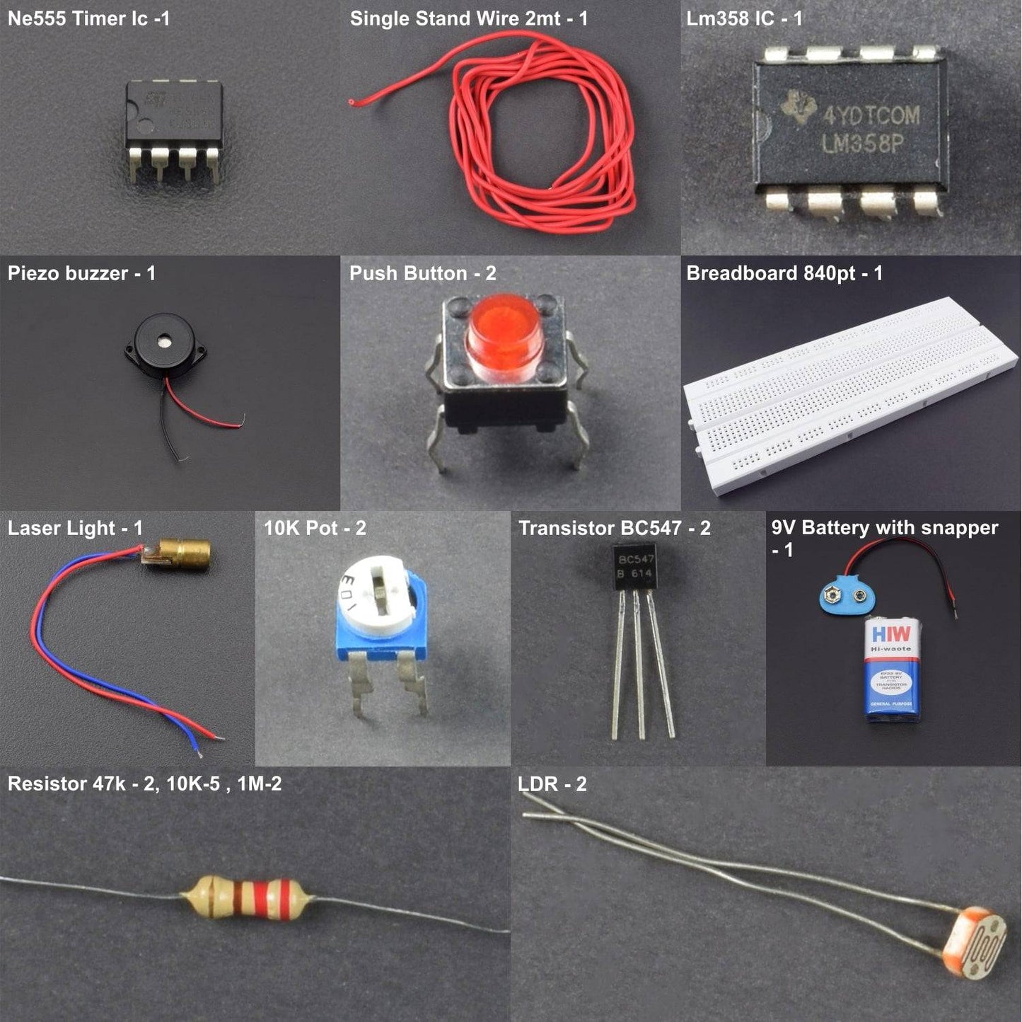
KIT INCLUDES:
- 555 Timer IC - 1
- LM358 IC - 1
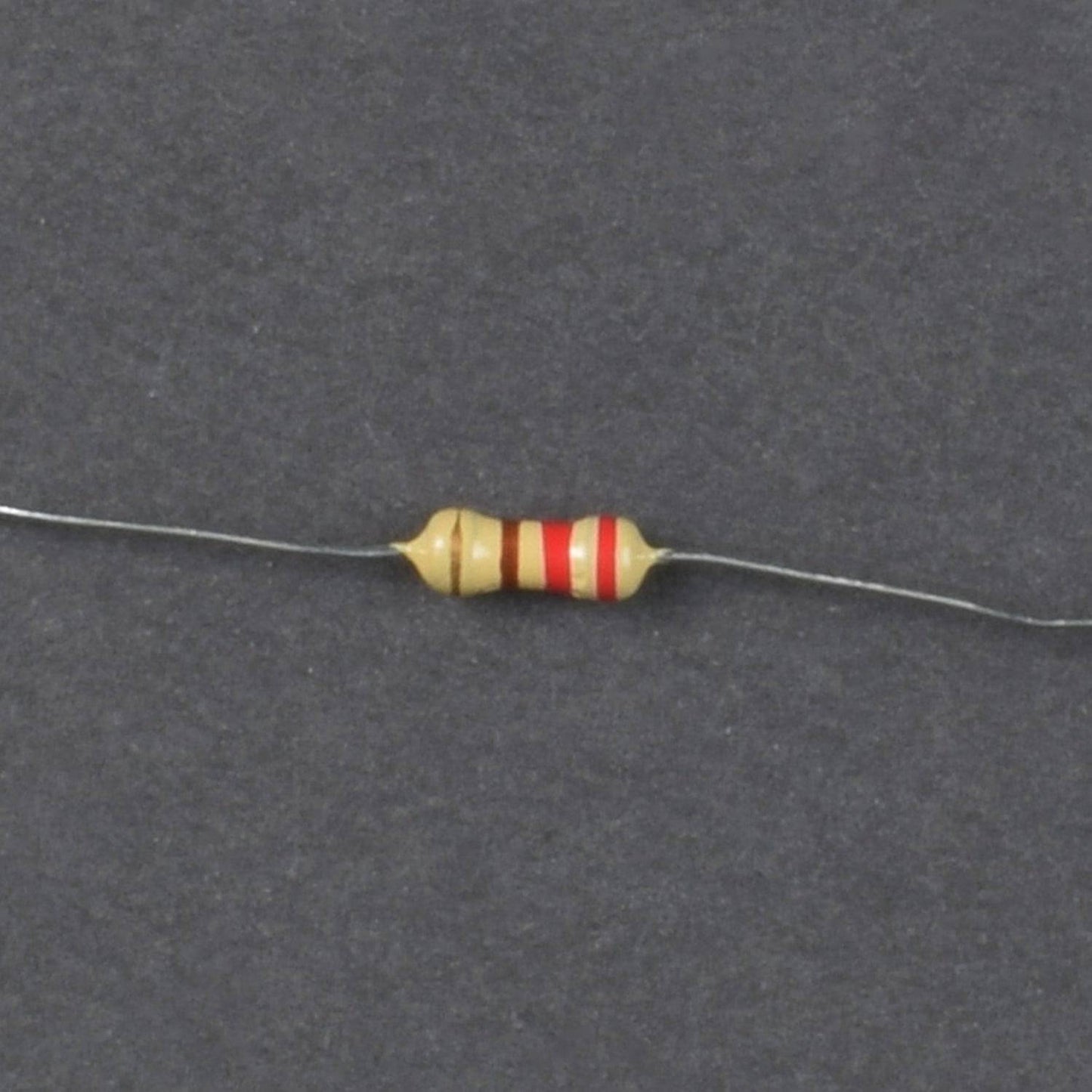
- Resistor 47k - 2, 10K-5 , 1M-2
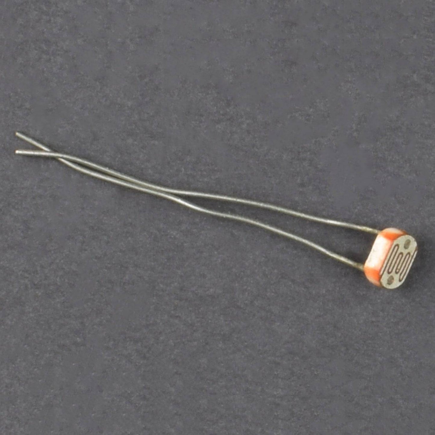
- LDR - 2
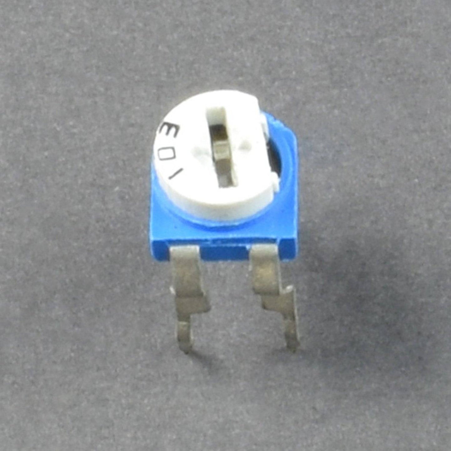
- 10K Pot - 2
- Transistor BC547 - 2
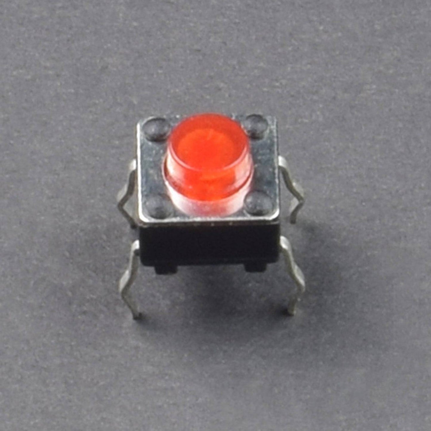
- Push Button - 2
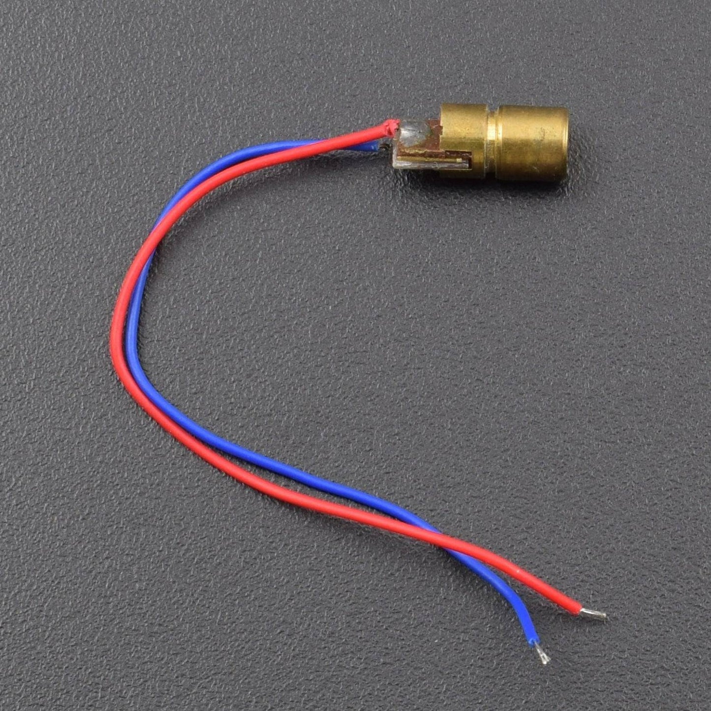
- Laser Light - 1
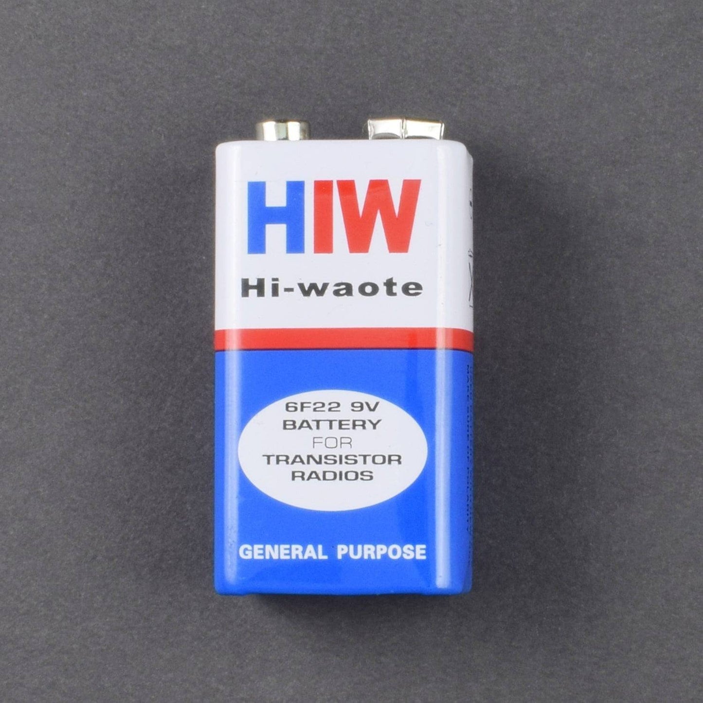
- Battery 9V -1
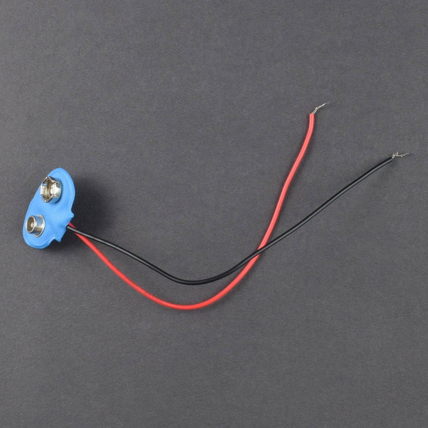
- Battery snapper - 1
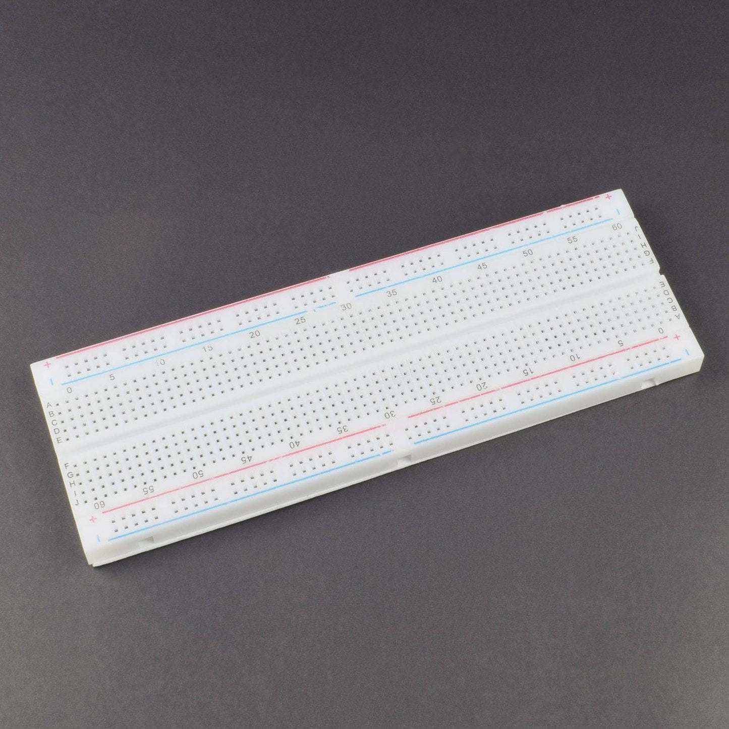
- Breadboard 840 points - 1
- Single Stand wire 2m - 1
- B-20 Piezo buzzer – 1
HARDWARE REQUIRED
- 555 Timer IC - 1
- LM358 IC - 1
- Resistor 47k - 2, 10K-5 , 1M-2
- LDR - 2
- 10K Pot - 2
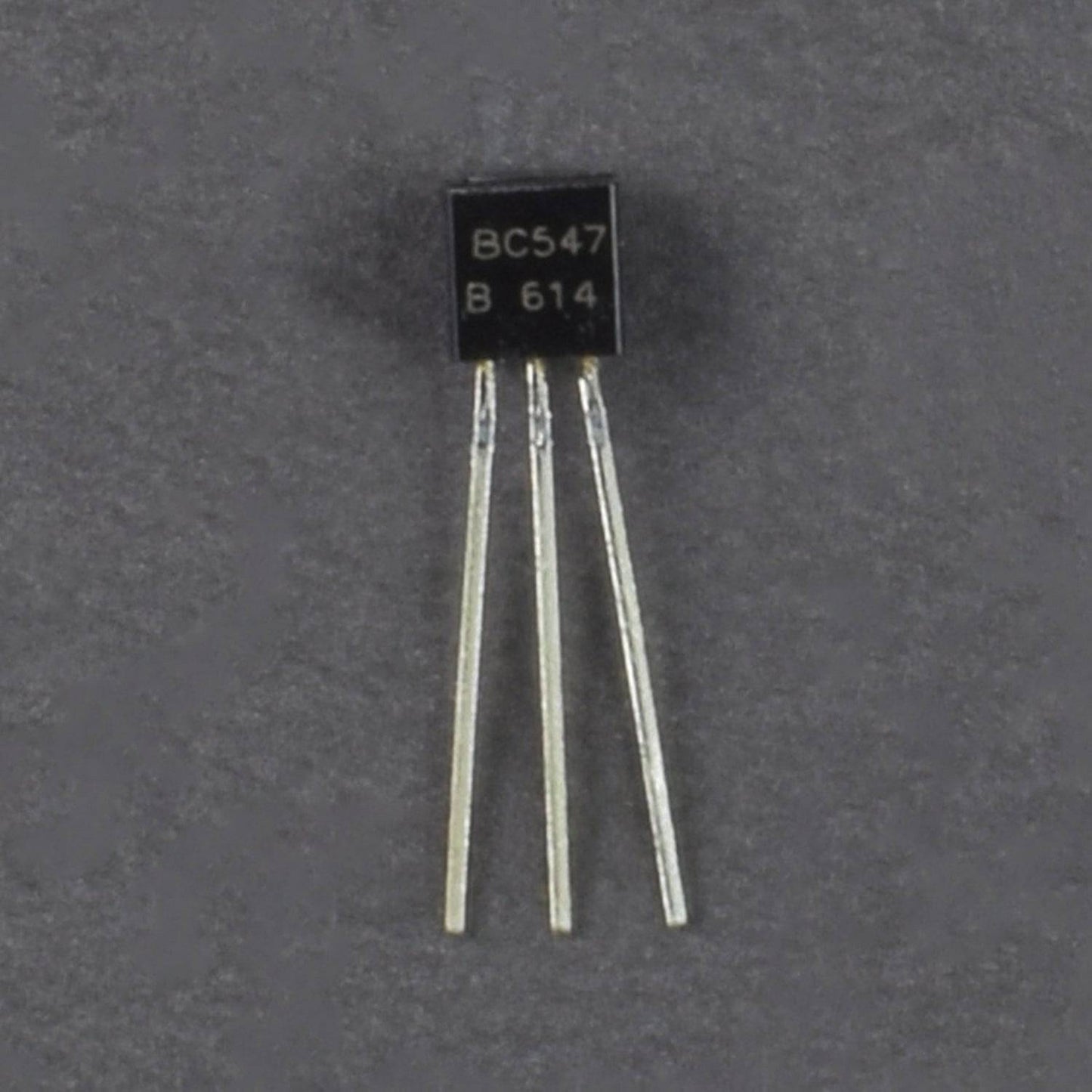
- Transistor BC547 - 2
- Push Button - 2
- Laser Light - 1
- Battery 9V -1
- Battery snapper - 1
- Breadboard 840 points - 1
- Single Stand wire 2m - 1
- B-20 Piezo buzzer – 1
SPECIFICATION
LM358 IC


The pin diagram of LM358 IC comprises of 8 pins, where
- Pin-1 and pin-8 are o/p of the comparator
- Pin-2 and pin-6 are inverting i/ps
- Pin-3 and pin-5 are non inverting i/ps
- Pin-4 is GND terminal
- Pin-8 is VCC+
Specifications:
- Range of Single power supply is from 3V to 32V
- Range of dual power supplies is from + or -1.5V to + or -16V
- The supply current drain is very low, i.e., 500 μA
- 2mV low i/p offset voltage
- Common mode i/p voltage range comprises ground
- It consists of two op-amps internally and frequency compensated for unity gain
- The large voltage gain is 100 dB
- Wide bandwidth is 1MHz
- Range of wide power supplies includes single and dual power supplies
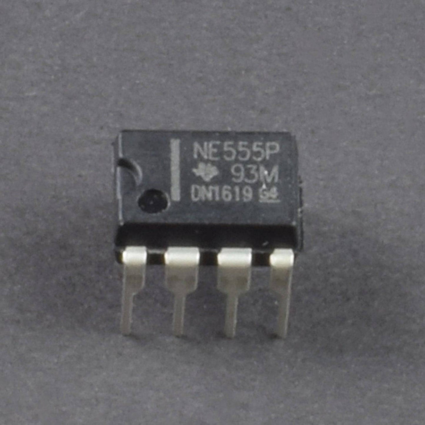
555 TIMER IC


Pin |
Name |
Purpose |
1 |
GND |
Ground reference voltage, low level (0 V) |
2 |
TRIG |
The OUT pin goes high and a timing interval starts when this input falls below 1/2 of CTRL voltage (which is typically 1/3 Vcc, CTRL being 2/3 Vcc by default if CTRL is left open). In other words, OUT is high as long as the trigger low. Output of the timer totally depends upon the amplitude of the external trigger voltage applied to this pin. |
3 |
OUT |
This output is driven to approximately 1.7 V below +Vcc, or to GND. |
4 |
RESET |
A timing interval may be reset by driving this input to GND, but the timing does not begin again until RESET rises above approximately 0.7 volts. Overrides TRIG which overrides threshold. |
5 |
CTRL |
Provides “control” access to the internal voltage divider (by default, 2/3 Vcc). |
6 |
THR |
The timing (OUT high) interval ends when the voltage at threshold is greater than that at CTRL (2/3 Vcc if CTRL is open). |
7 |
DIS |
Open collector output which may discharge a capacitor between intervals. In phase with output. |
8 |
Vcc |
Positive supply voltage, which is usually between 3 and 15 V depending on the variation. |
TRANSISTOR


10K POTENTIOMETER


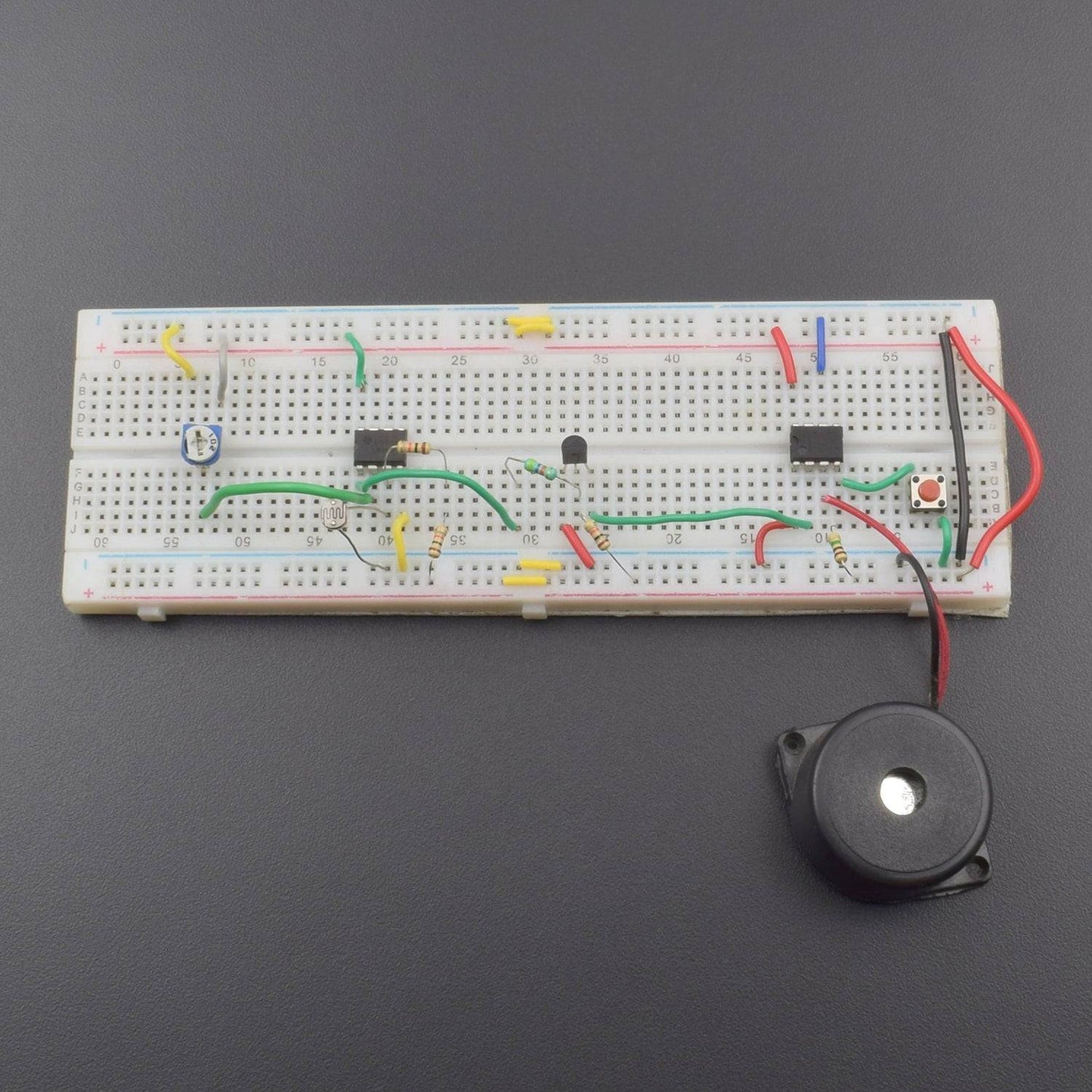
CIRCUIT DESCRIPTION

- 10K pot, LM358 IC, 555 Timer IC, Push Button and Transistor BC547 connected to the Breadboard.
- 10K Pot 1st leg(left) connected to the GND and 2nd leg(right) connected to the positive supply.
- 10K Middle leg connected to the LM358 IC Pin No. 2.
- LM358 IC Pin No. 4 is GND and Pin No. 8 connected to the positive supply.
- LM358 IC Pin No. 3 to connected LDR and LDR 2nd leg is GND.
- LM358 IC Pin No. 3 to connected 20K(10K+10K) Resistor and Resistor 2nd leg connected to the positive supply.
- LM358 IC Pin No. 1 to connected 47K Resistor and Resistor 2nd leg connected to the BC547 Transistor Middle leg.
- BC547 Transistor 1st leg(left) is GND and BC547 Transistor 2nd leg(right) to connected 10K Resistor and Resistor 2nd leg connected to the positive supply.
- BC547 Transistor 2nd leg(right) connected to the 555 Timer IC Pin No. 2.
- 555 Timer IC Pin No. 1 & 6 are GND and Pin No. 8 connected to the positive supply.
- 555 Timer IC Pin No. 3 to connected piezo buzzer positive leg and negative leg is GND.
- 555 Timer IC Pin No. 4 to connected 1M Resistor and Resistor 2nd leg connected to the positive supply.
- 555 Timer IC Pin No. 4 to connected Push Button 1st leg and Push Button 2nd leg is GND.
- Laser Light positive leg connected to the positive supply and negative leg is GND.
- Breadboard connection positive to positive and negative to negative.
WORKING
In this circuit, the LM358 ic is working as a comparator and IC LM555 is wired as a bistable multivibrator. The transistor BC547 is wired as a switch to provide the negative trigger at pin 2 of LM555. The 10K pot is used to adjust the sensitivity of the circuit.
When anyone interrupts the laser beam, the LDR will go to darkness which increases the resistance across LDR, which in turn increases the voltage across it. When the voltage at Non-Inverting terminal (PIN 3) will greater than Inverting terminal (PIN 2) the output of the comparator goes high. Thus the output of the transistor goes low and triggers the 555, which sounds the buzzer