
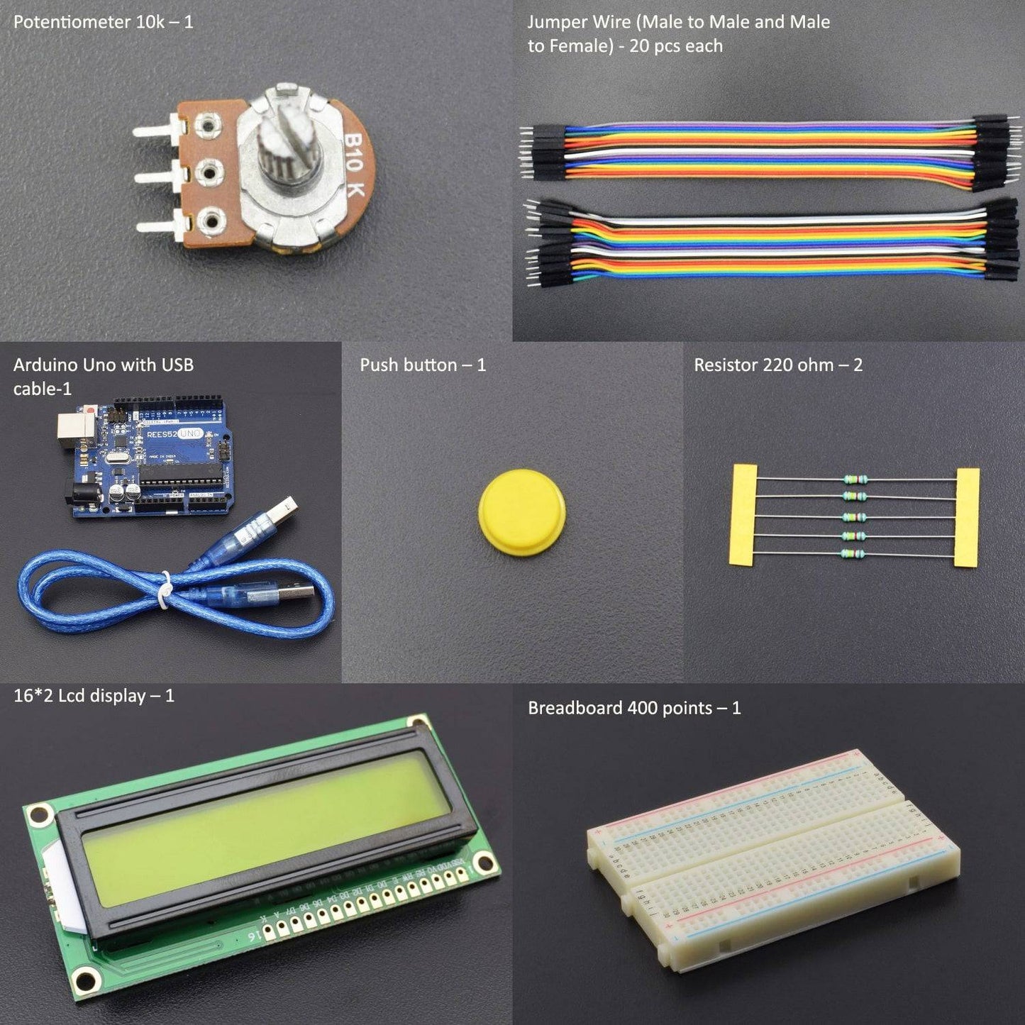
KIT INCLUDES:
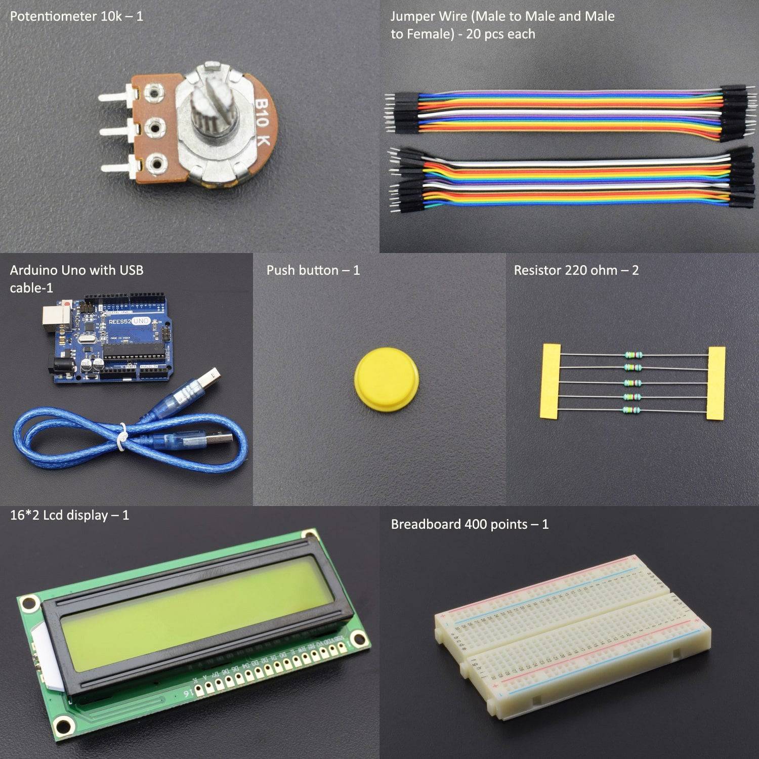
- Arduino Uno with USB cable – 1
- 16*2 Lcd display – 1
- Breadboard 400 points – 1
- Push-button – 1
- Resistor 220 ohm – 2
- Jumper wire male to female – 20 PIECES
- Jumper wire male to male – 20 PIECES
- 10k Potentiometer - 1
Introduction
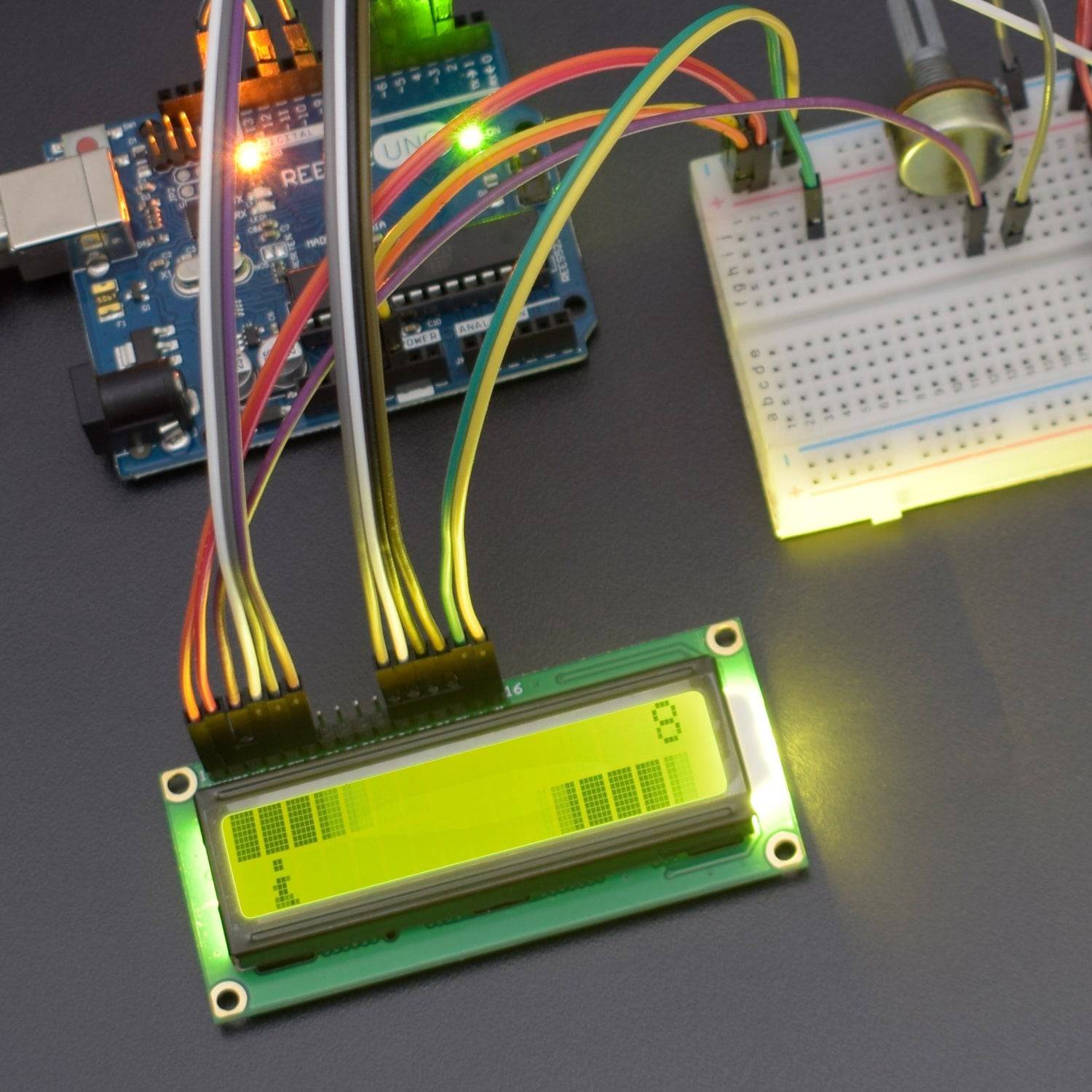
In this project, we are making a jumping jack game using Arduino Uno with a 16*2 LCD Display. In the sketch, a basic mini-program of a retro video game replicating the Super Mario Bros arcade game is a good code to explore and study if you are into programming.
HARDWARE REQUIRED
- Arduino Uno with USB cable – 1
- 16*2 Lcd display – 1
- Breadboard 400 points – 1
- Push-button – 1
- Resistor 220 ohm – 2
- Jumper wire male to female – 20 PIECES
- Jumper wire male to male – 20 PIECES
- 10k Potentiometer - 1
SOFTWARE REQUIRED
Arduino IDE 1.8.5 (programmable platform for Arduino)
Click To Download:https://www.arduino.cc/en/Main/Software

SPECIFICATIONS
16*2 LCD Display
- LCD Display Mode: STN, Positive, Transflective
- Display Color: Deep Blue/ Yellow Green
- Viewing Angle: 6H
- Driving Method: 1/16 duty, 1/5 bias
- Back Light: Yellow-Green LED backlight
- Outline Dimension: 803615.8 MAX

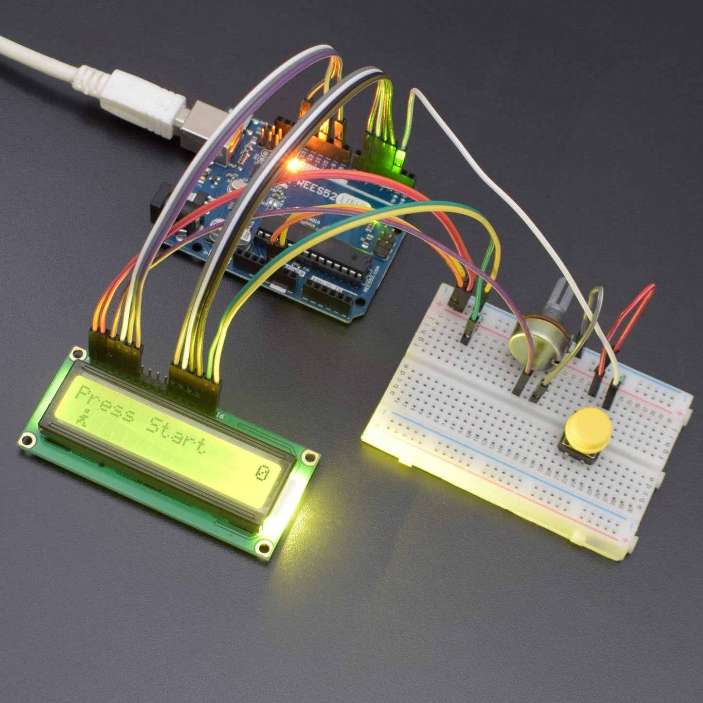
CIRCUIT DIAGRAM

Start off with the Arduino unpowered. Do NOT plug in the USB cable. That will happen in a later step when it is time to program it and try the game out.
Use long hookup wire to connect the 5V signal on the Arduino to the far left of the red row at the top of the breadboard.
Use long hookup wire to connect the GND signal.
The LCD (Liquid Crystal Display) module has a 16-pin male header on the underside.
These pins are (from left to right):
GND - power ground signal
VCC - positive power signal
V0 - contrast adjust
RS - register select
R/W - Read/write select
E - operation enable signal
DB0 - data bit 0 (not used here)
DB1 - data bit 1 (not used here)
DB2 - data bit 2 (not used here)
DB3 - data bit 3 (not used here)
DB4 - data bit 4
DB5 - data bit 5
DB6 - data bit 6
DB7 - data bit 7
LED+ - backlight LED positive
LED- - backlight LED negative
Connect DB7 to Arduino pin 3
Connect DB6 to Arduino pin 4
Connect DB5 to Arduino pin 5
Connect DB4 to Arduino pin 6
Connect E to Arduino pin 9
Connect R/W to Arduino pin 10 (or to black row at top of breadboard)
Connect RS to Arduino pin 11
Connect V0 to Arduino pin 12 (or to black row at top of breadboard)
Plug the pushbutton somewhere to the left of the LCD screen, straddling the channel running along the center of the breadboard (see picture above). Connect one of the top two pins of the button to the black row at the top of the breadboard using short hookup wire. Connect the other pin at the top of the button to pin 2 of the Arduino.
CODE
Click to see the code or copy the link:
https://drive.google.com/open?id=1j42FmiBrqBrOKKNurs2X-Mb3m4rpw3h2
WORKING
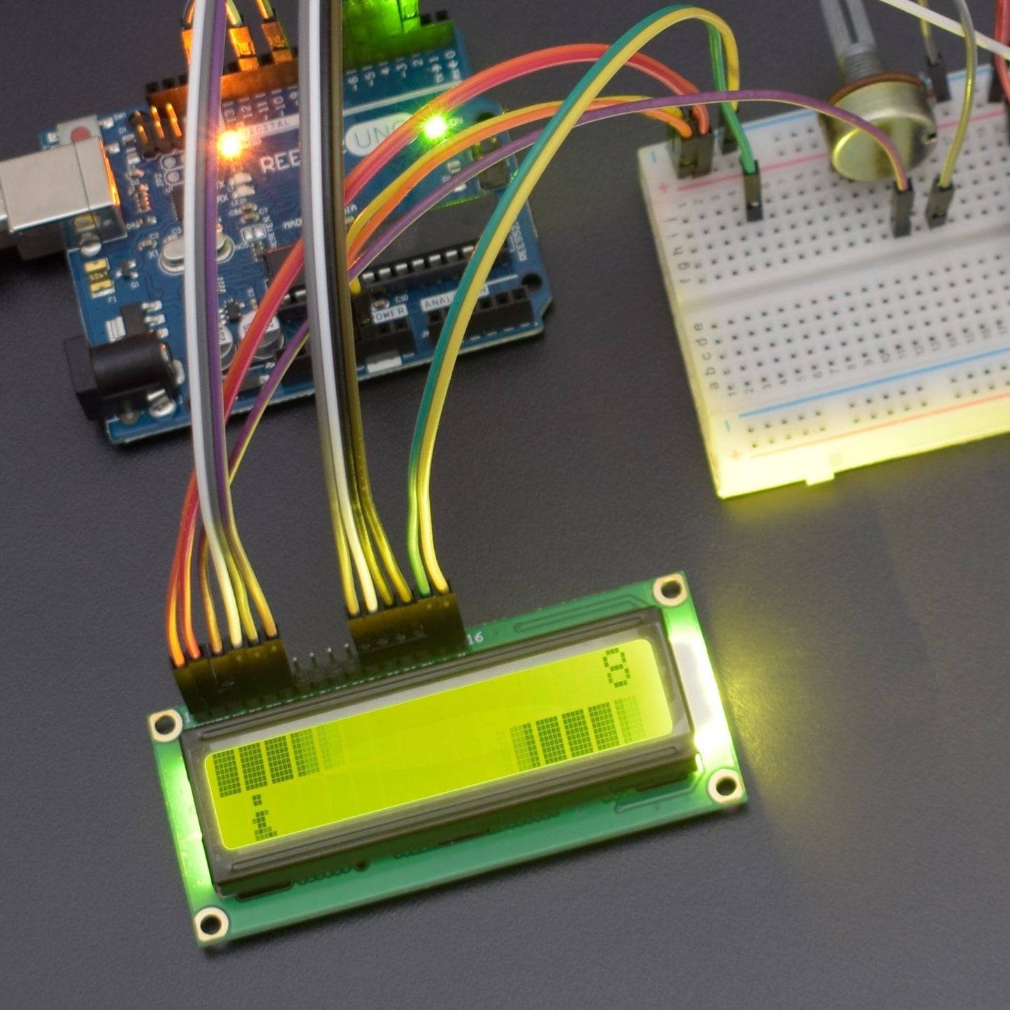
a game in which we jump over the obstacles to create a score. We jump using the push button. It is a side-scrolling jumping game. Connect All the circuit, and start the game. jump the character jack by pressing push-button


