


vendor-unknown
MAKE A HOME AUTOMATION SYSTEM USING TSOP AND 1 CHANNEL 5V RELAY INTERFACING WITH 4017 IC - KT855
MAKE A HOME AUTOMATION SYSTEM USING TSOP AND 1 CHANNEL 5V RELAY INTERFACING WITH 4017 IC - KT855
SKU:KT855
1000 in stock
Couldn't load pickup availability
- For Bulk Order Click Here
- Need Customer Support?
- Free Delivery Above 999/-
Note: In case you receive a damaged or faulty product, please return it in the original box with all foam and packaging. Returns will not be accepted if further damage occurs due to improper packing.
For refund/return/replacement, call us at +91 95991 22209 or mail us at support@rees52.com
Delivery Time
Delivery Time
- Delivery time with the Express Shipping option is 2-3 working days, and with the Standard Shipping option is 5-6 working days. It varies based on location, reliant on courier services.
- Delivery time if the order item is on Preorder Status is 15-20 working days.
COD (Cash on Delivery)
COD (Cash on Delivery)
- For COD you have to pay extra charges of Rs 350/- before the shipment. (We will share the company QR Code, UPI ID or Account details for the same)

KIT INCLUDES
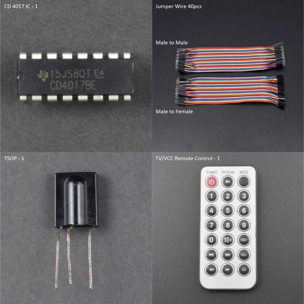
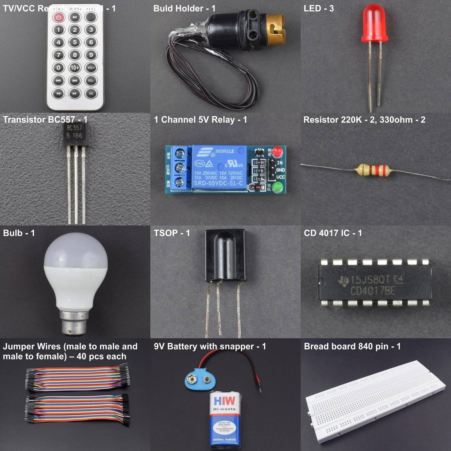
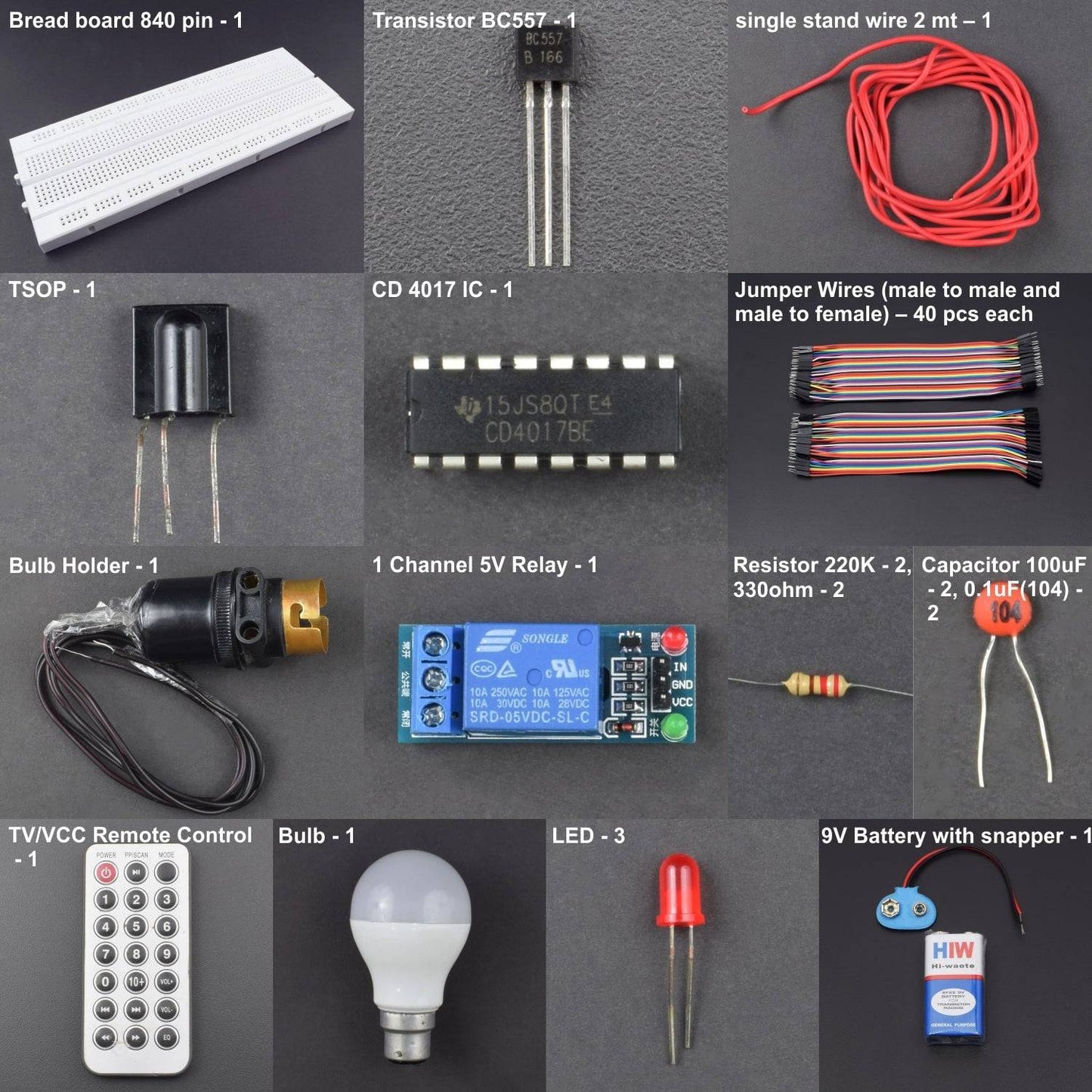
- TSOP - 1
- TV/VCC Remote Control - 1
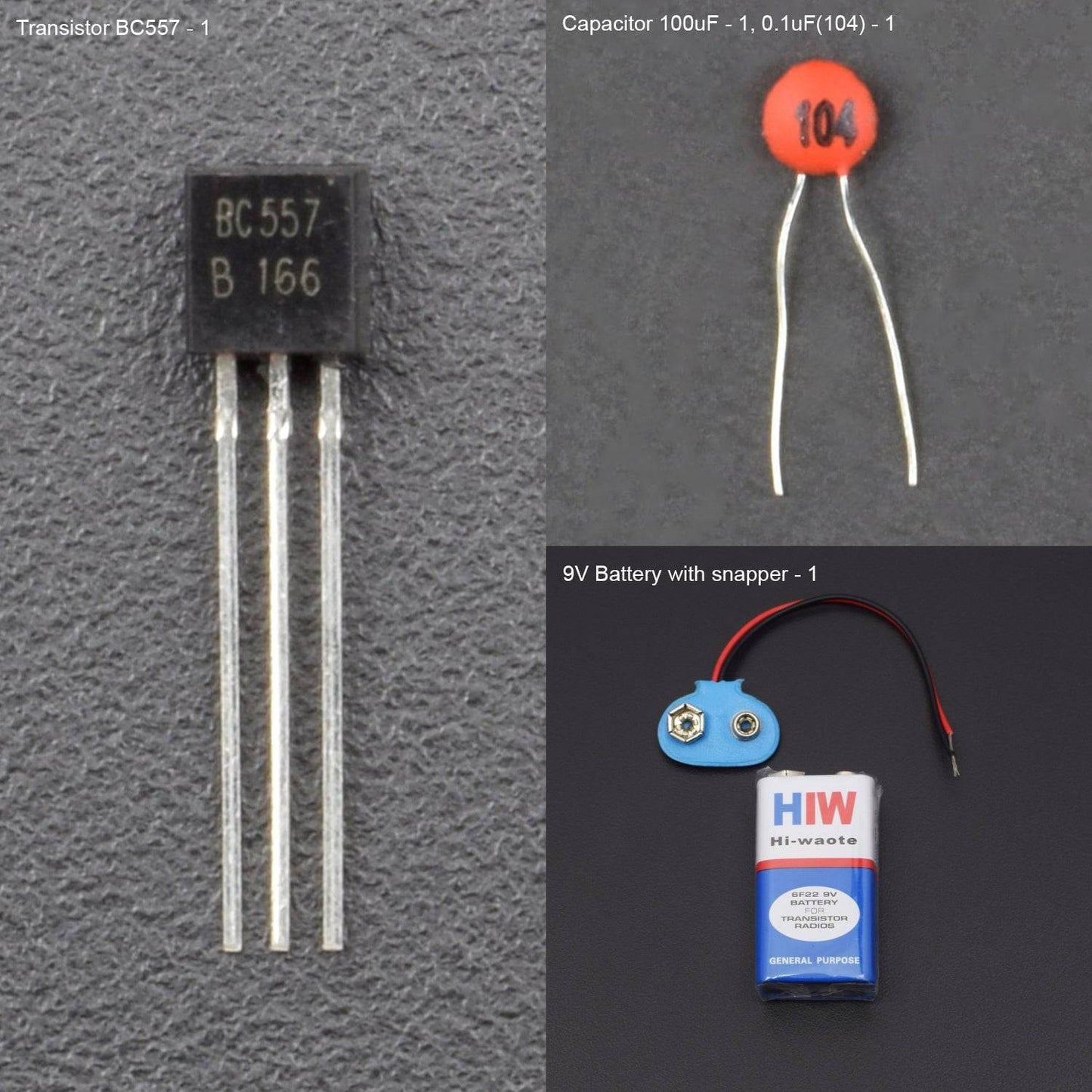
- Transistor BC557 - 1
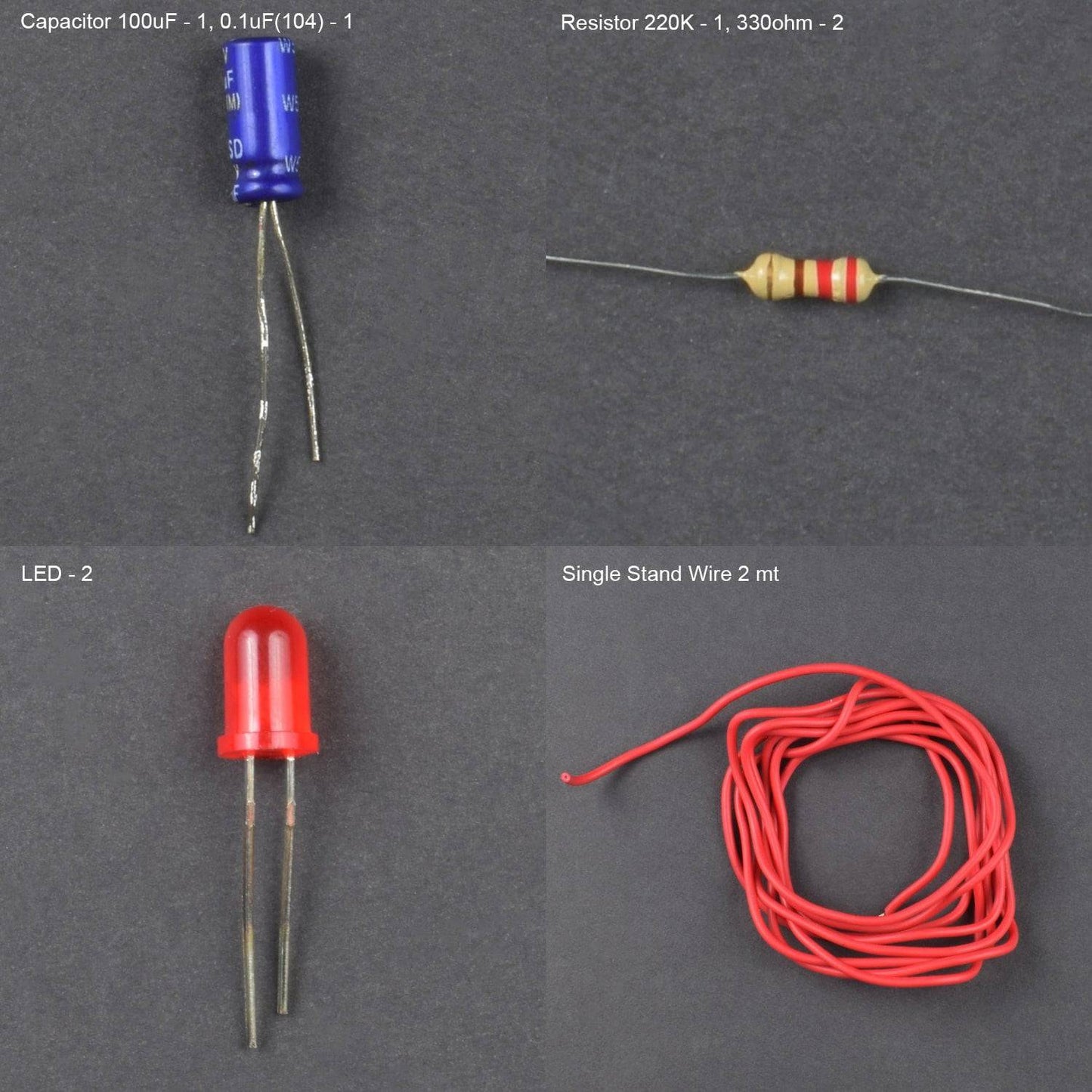
- Capacitor 100uF - 2, 0.1uF(104) - 2
- Resistor 220K - 2, 330ohm - 2
- LED - 3
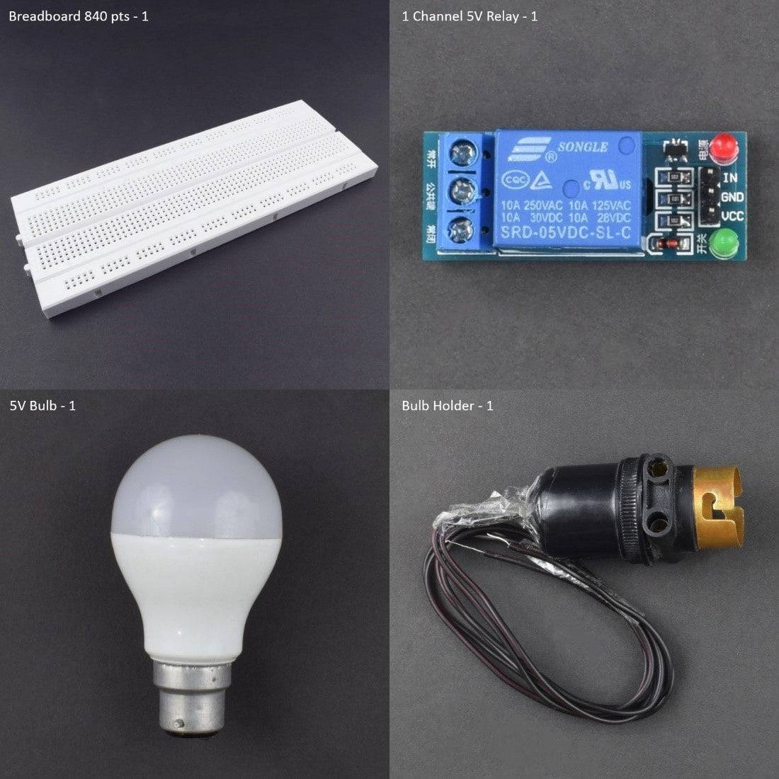
- 1 Channel 5V Relay - 1
- 5 v 1amp adapter –1
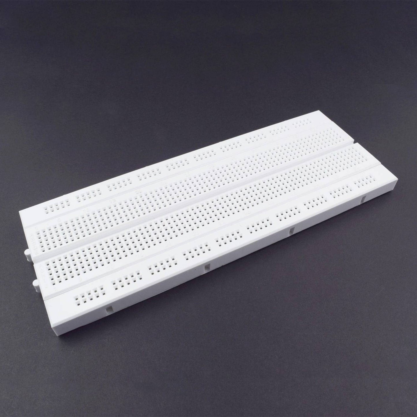
- bread board 840 pin -1
- single stand wire 2 mt – 1
- CD 4017 IC - 1
- Jumper Wires male to male– 40 pcs
- Jumper Wires male to Female– 40 pcs

HARDWARE REQUIRED
- TSOP - 1
- TV/VCC Remote Control - 1
- Transistor BC557 - 1
- Capacitor 100uF - 2, 0.1uF(104) - 2
- Resistor 220K - 2, 330ohm - 2
- LED - 3
- 1 Channel 5V Relay - 1
- 5 v 1amp adapter – 1 or any 5v Power source
- bread board 840 pin - 1
- single stand wire 2 mt – 1
- CD 4017 IC - 1
- Jumper Wires male to male– 40 pcs
- Jumper Wires male to Female– 40 pcs
SPECIFICATION
Power Source: 5v 1amp adapter
PIN DESCRIPTION
7 segments Led display
- Number of I/O Channels: 1
- Type: Digital
- Control signal: TTL level
- Max. Allowable Voltage: 250VAC/110VDC
- Max. Allowable Power Force: From C(800VAC/240W), From A(1200VA/300W)
7 segments Led display

The importance Pins look at table below.

- Pin 16 is positive power supply and pin 8 is a ground.
The power supply range of 3 volts to 16 volts and Maximum power supply voltage at pin 1 must not much than 18 volts.
-
Pin 13 is Clock enabled pins to controls the clock.
When it is “0” logic, the clock is enabled and the counter advances one count for each clock pulse. - When “1” logic, the clock input is stop, and the counter does nothing even when clock pulse arrive.
- Pin 14 is the clock triggers one count.
The clock pulse must be “clean”.
If they are “noisy” the counter may advance two or more times during each clock pulse.
- Pin 15 is the reset pin. Normally, it is “0”.
When made “1”, the counter is reset to “0”.
- Pins 1-7 and 9-11 are the decoded output pins.
The active count pin goes high and all others remain low.
- Pin 12 is Carry output, for the clock input of an additional counter or an external circuit that the count is complete.
7 segments Led display


BC557 Transistor


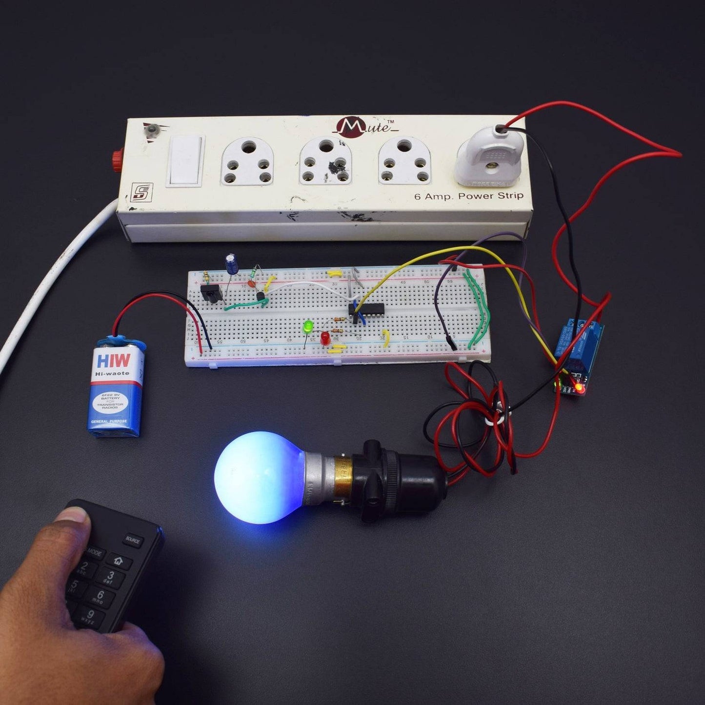
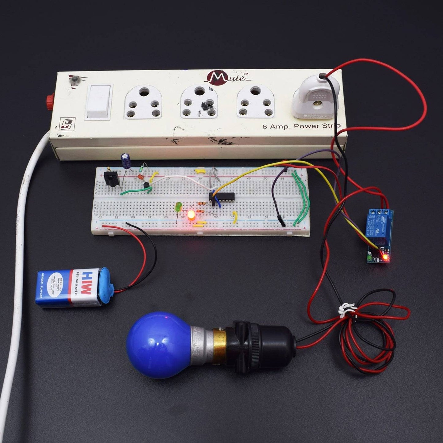
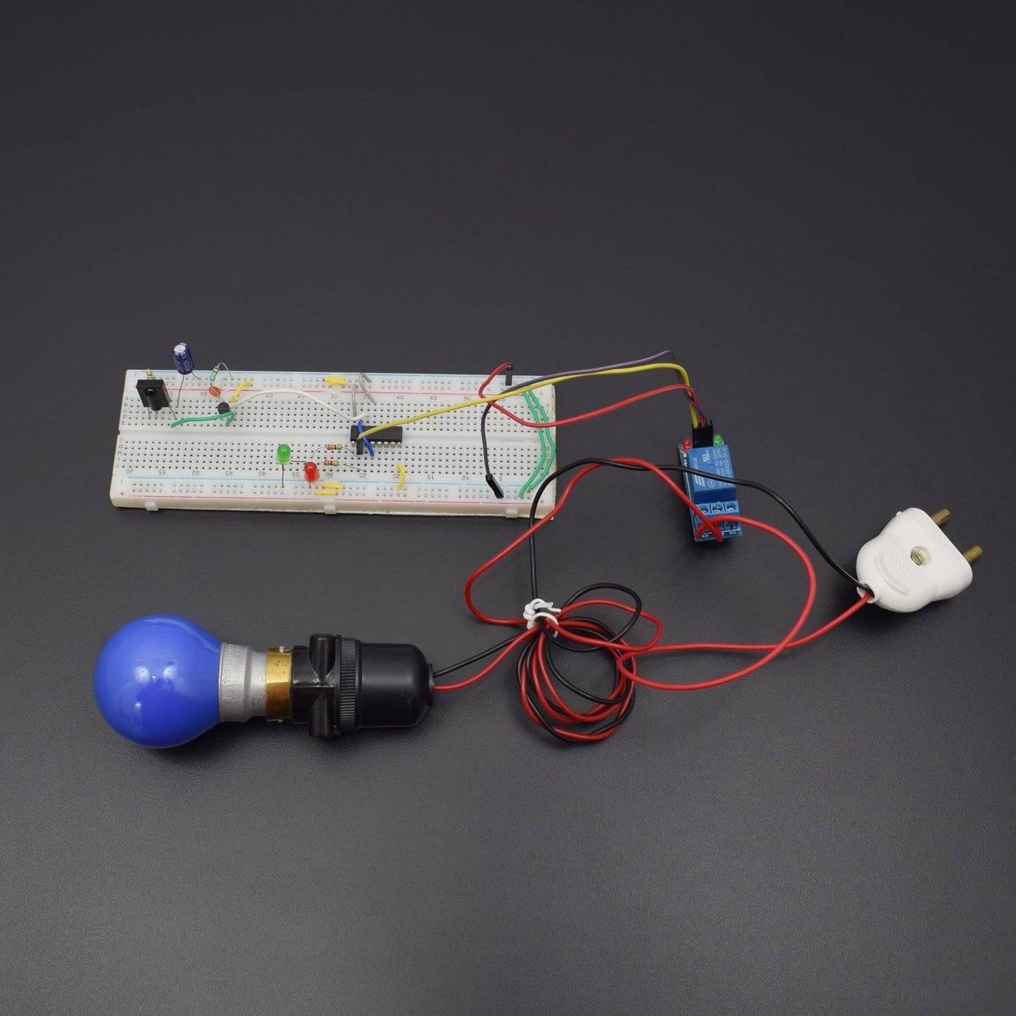
CIRCUIT CONNECTION
- 4017 IC Connected to the Breadboard and Pin no. 8, 13 are GND.
- 4017 IC Pin no. 16 connected to the positive supply and Pin no. 4 & 15 connected to the each other.
- 4017 IC Pin no. 3 to connected 330 ohm Resistor and resistor 2nd leg to connected LED positive leg and LED negative leg is GND.
- 4017 IC Pin no. 2 to connected 330 ohm Resistor and resistor 2nd leg to connected LED positive leg and LED negative leg is GND.
- 4017 IC Pin no. 14 connected to the Transistor 1st leg(E), Transistor 1st leg to connected 220K Resistor and Resistor 2nd leg connected to the positive supply.
- Transistor 1st leg(E) to connected 0.1uF capacitor and capacitor 2nd leg is GND and Transistor 3rd leg(C) is GND.
- Transistor 2nd leg(B) connected to 3rd Pin of TSOP and TSOP 3rd Pin to connected 100uF capacitor positive leg and capacitor negative leg is GND.
- TSOP 1st Pin is GND and 2nd Pin to connected 47ohm Resistor and Resistor 2nd leg connected to the positive supply.
- 5 volt single channel relay module we connect on bread boardvcc to vcc ,gnd to gnd, input of relay module connect to the 4017 IC PIN NO 2 and we connect no & nc point of relay to ac 220volt.
- Breadboard connection positive to positive and negative to negative

WORKING
This remote control for home appliances lets you connect your regular everyday appliances to be controlled by a remote. All you have to do is connect this circuit to any of your home appliances (lamp, fan, radio, etc) and you are good to go. The appliance can now be controlled by a remote control working at the designated frequency. The circuit can be activated from up to 10 meters.