


vendor-unknown
Make a Home Automation fan over Wi-Fi controlled app using WROOM-32 Wi-fi Module with 5v 1-Channel Relay Module - KT583
Make a Home Automation fan over Wi-Fi controlled app using WROOM-32 Wi-fi Module with 5v 1-Channel Relay Module - KT583
SKU:KT583
Low stock: 4 left
Couldn't load pickup availability
- For Bulk Order Click Here
- Need Customer Support?
- Free Delivery Above 999/-
Note: In case you receive a damaged or faulty product, please return it in the original box with all foam and packaging. Returns will not be accepted if further damage occurs due to improper packing.
For refund/return/replacement, call us at +91 95995 94520 or email us at support@rees52.com
Delivery Time
Delivery Time
- Delivery time with the Express Shipping option is 2-3 working days, and with the Standard Shipping option is 5-6 working days. It varies based on location, reliant on courier services.
- Delivery time if the order item is on Preorder Status is 15-20 working days.
COD (Cash on Delivery)
COD (Cash on Delivery)
- For COD you have to pay extra charges of Rs 350/- before the shipment. (We will share the company QR Code, UPI ID or Account details for the same)
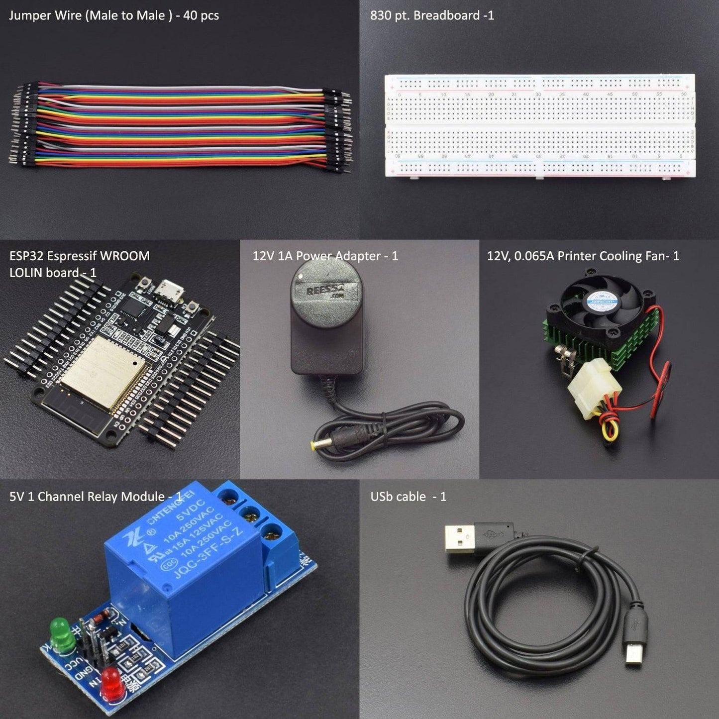
KIT INCLUDED
- ESP32 Wroom32 Wi-Fi Board - 1
- NodeMcu USB cable - 1
- 1channel 5V relay Module - 1
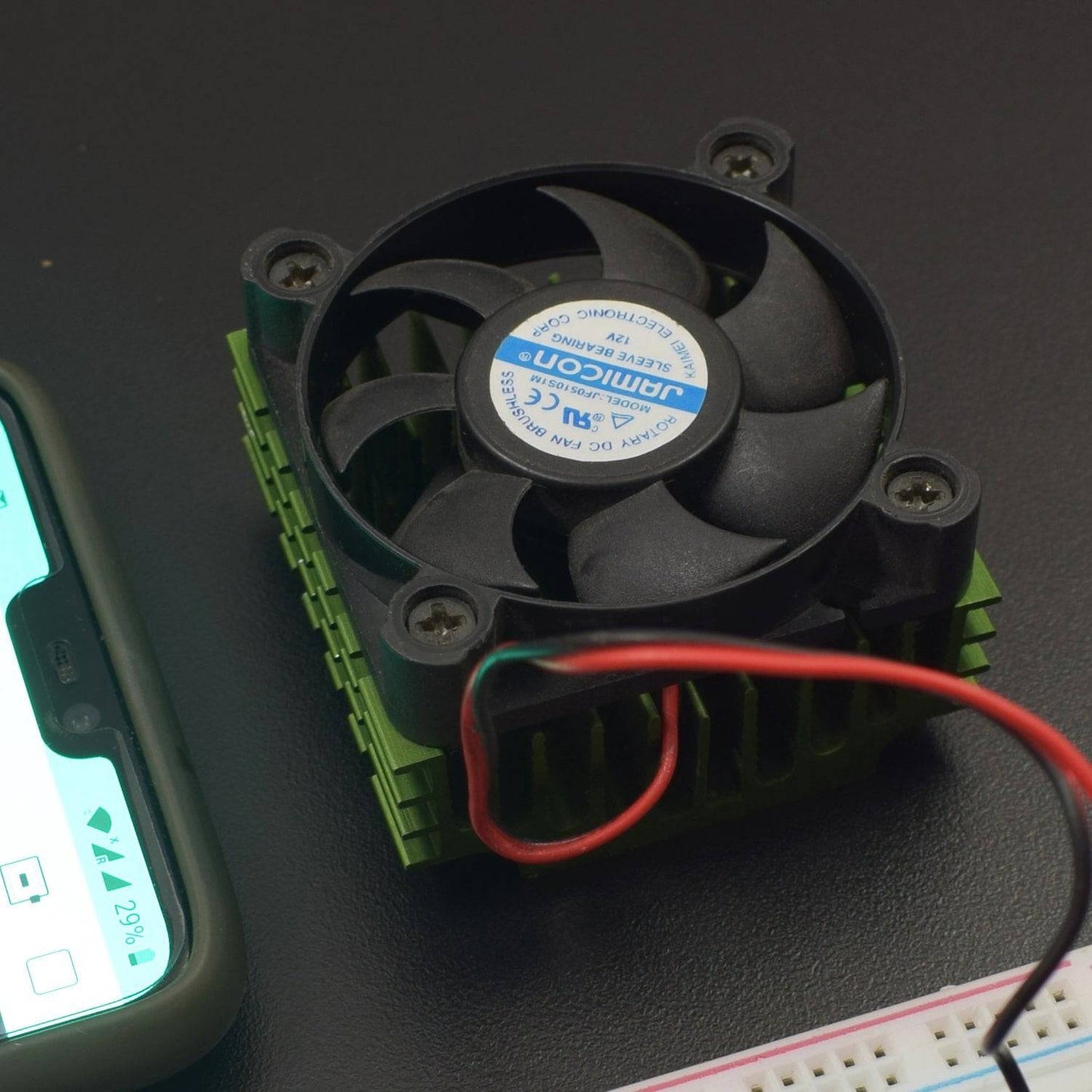
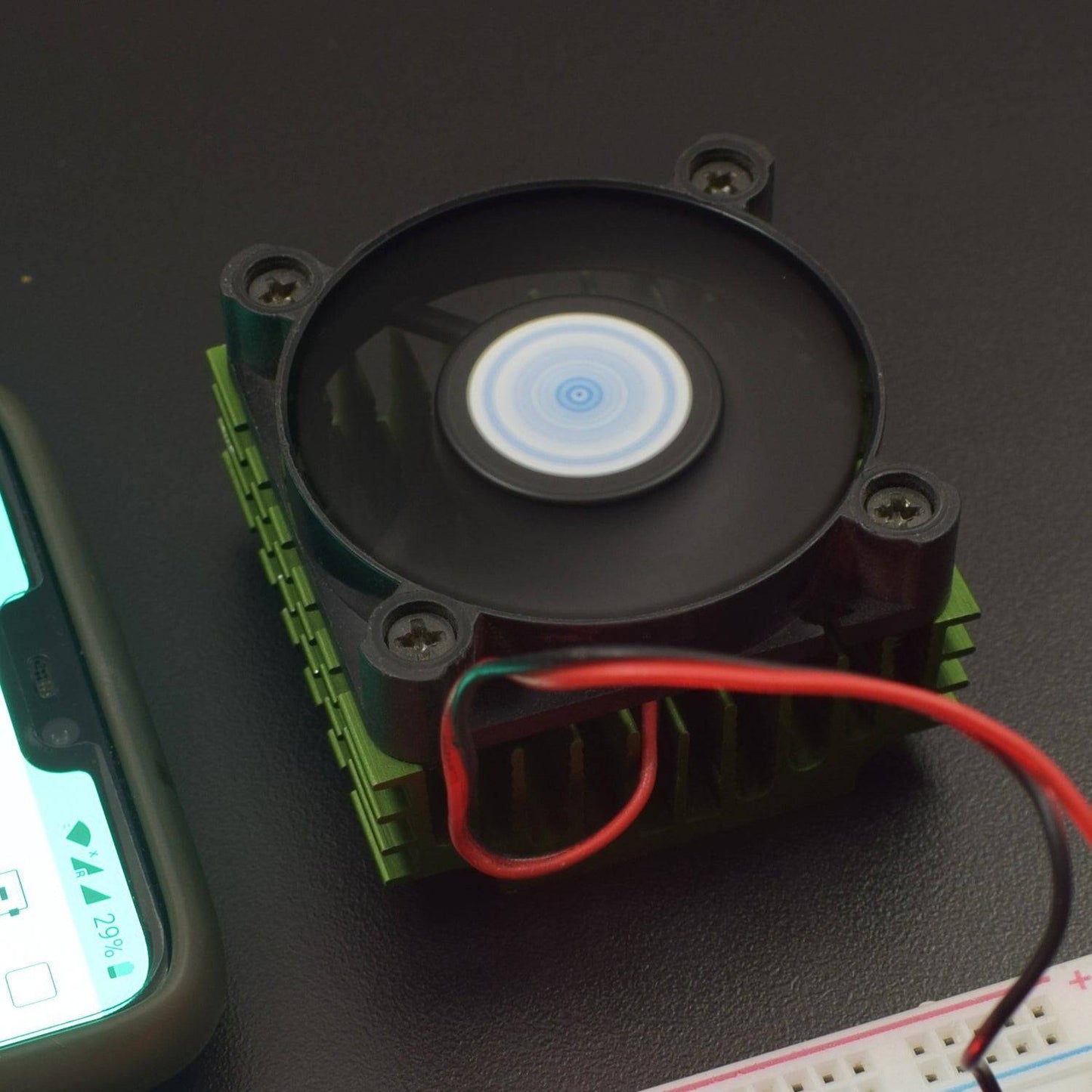
- 12V DC 0.065A fan – 1
- 12V 1A ac to dc adapter - 1
- Jumper Wires (male to male) – 20 pcs each
- Jumper Wires (male to Female) – 20 pcs each
- 830 pt. breadboard - 1
Introduction
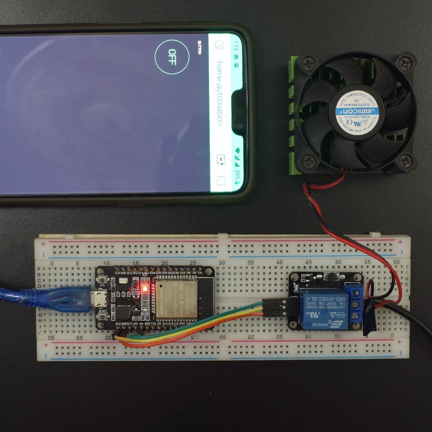
In this project, we have used ESP32 to wirelessly operate a 12V fan over the BLYNK app in an android smartphone.
HARDWARE REQUIRED
- ESP32 Wroom32 Wi-Fi Board - 1
- NodeMcu USB cable - 1
- 1channel 5V relay Module - 1
- 12V DC 0.065A fan – 1
- 12V 1A ac to dc adapter - 1
- Jumper Wires (male to male) – 20 pcs each
- Jumper Wires (male to Female) – 20 pcs each
- 830 pt. breadboard - 1
SOFTWARE REQUIRED
Arduino IDE 1.8.5 (programmable platform for Arduino)
Click To Download: https://www.arduino.cc/en/Main/Software

SPECIFICATIONS
ESP-32 WROOM Wi-fi Board
ESP32-WROOM-32 is a powerful, generic Wi-Fi+BT+BLE MCU module that targets a wide variety of applications, ranging from low-power sensor networks to the most demanding tasks, such as voice encoding, music streaming, and MP3 decoding.
The integration of Bluetooth, Bluetooth LE and Wi-Fi ensures that a wide range of applications can be targeted and that the module is future proof: using Wi-Fi allows a large physical range and direct connection to the internet through a Wi-Fi router while using Bluetooth allows the user to conveniently connect to the phone or broadcast low energy beacons for its detection. The sleep current of the ESP32 chip is less than 5 μA, making it suitable for battery-powered and wearable electronics applications.

Key Features
- 18 Analog-to-Digital Converter (ADC) channels
- 10 Capacitive sensing GPIOs
- 3 UART interfaces
- 3 SPI interfaces
- 2 I2C interfaces
- 16 PWM output channels
- 2 Digital-to-Analog Converters (DAC)
- 2 I2S interfaces
Pin Description
GPIO Pins
ESP32 Wroom32 DevKit has total 25 GPIOs out of that few pins are Input-only Pins,
Input Only Pins
- GPIO 34
- GPIO 35
- GPIO 36
- GPIO 39
Not all pins have input pullup, you need external pullup on these pins when using as input pullup
Pins with internal pull-up INPUT_PULLUP
- GPIO14
- GPIO16
- GPIO17
- GPIO18
- GPIO19
- GPIO21
- GPIO22
- GPIO23
Pins without internal pull up
- GPIO13
- GPIO25
- GPIO26
- GPIO27
- GPIO32
- GPIO33
ESP32 BOARD INSTALLATION
----------------------------------------------------------------------------------------------------------------------------------------------------------------------------------------------------------------------
STEP- 1Installation instructions using Arduino IDE Boards Manager
----------------------------------------------------------------------------------------------------------------------------------------------------------------------------------------------------------------------
Starting with 1.6.4, Arduino allows the installation of third-party platform packages using Boards Manager. It has packages available for Windows, Mac OS, and Linux (32 and 64 bit).
- Install the current upstream Arduino IDE at the 1.8 level or later. The current version is on the Arduino website.
- Start Arduino and open the Preferences window.
- Enter https://dl.espressif.com/dl/package_esp32_index.json into the Additional Board Manager URLs field. You can add multiple URLs, separating them with commas.
- Open Boards Manager from Tools > Board menu and install the esp32 platform (and don't forget to select your ESP32 board from Tools > Board menu after installation).
Stable release link:https://dl.espressif.com/dl/package_esp32_index.json
Development release Link:https://dl.espressif.com/dl/package_esp32_dev_index.json
----------------------------------------------------------------------------------------------------------------------------------------------------------------------------------------------------------------------
Step 2: Insert Link for .json Espressif Package Files into Arduino IDE
----------------------------------------------------------------------------------------------------------------------------------------------------------------------------------------------------------------------

Paste the copied link and insert it in Arduino IDE using following sequence-
File - menu - Preferences
Paste copied link into the area shown in the Highlighted box in the below image. Close and restart the Arduino IDE.
----------------------------------------------------------------------------------------------------------------------------------------------------------------------------------------------------------------------
Step 3: Tools - Boards Manager
----------------------------------------------------------------------------------------------------------------------------------------------------------------------------------------------------------------------

Tools - Boards manager and search for ESP32 and install the libraries/files given under heading ESP32 by ESPressif community.
Restart the Arduino IDE once again

----------------------------------------------------------------------------------------------------------------------------------------------------------------------------------------------------------------------
Step 4: Selecting WEMOS LOLIN32 Board in Arduino IDE
----------------------------------------------------------------------------------------------------------------------------------------------------------------------------------------------------------------------

Go to Tools à Boards (scroll down the list of boards) - Select WEMOS LOLIN32.
Select the Port number at which you have connected ESP32. The rest of the settings can be left to default values.
LIBRARY REQUIRED
Before uploading the code, must install this library:
ESP32WiFi.hhttps://github.com/espressif/arduino-esp32/blob/master/docs/arduino-ide/boards_manager.md
BLYNK library https://github.com/blynkkk/blynk-library/releases/tag/v0.6.1
How to add the widget in Blynk
- Create a new project in the BLYNK app
- Choose the ESP32 DEV board
- Create the project

Touch the add icon to add button as shown in figure
Touch the button to add button in your project

Select the pin GP4 to control the 4th pin of ESP32 and go to back now your app is ready to use


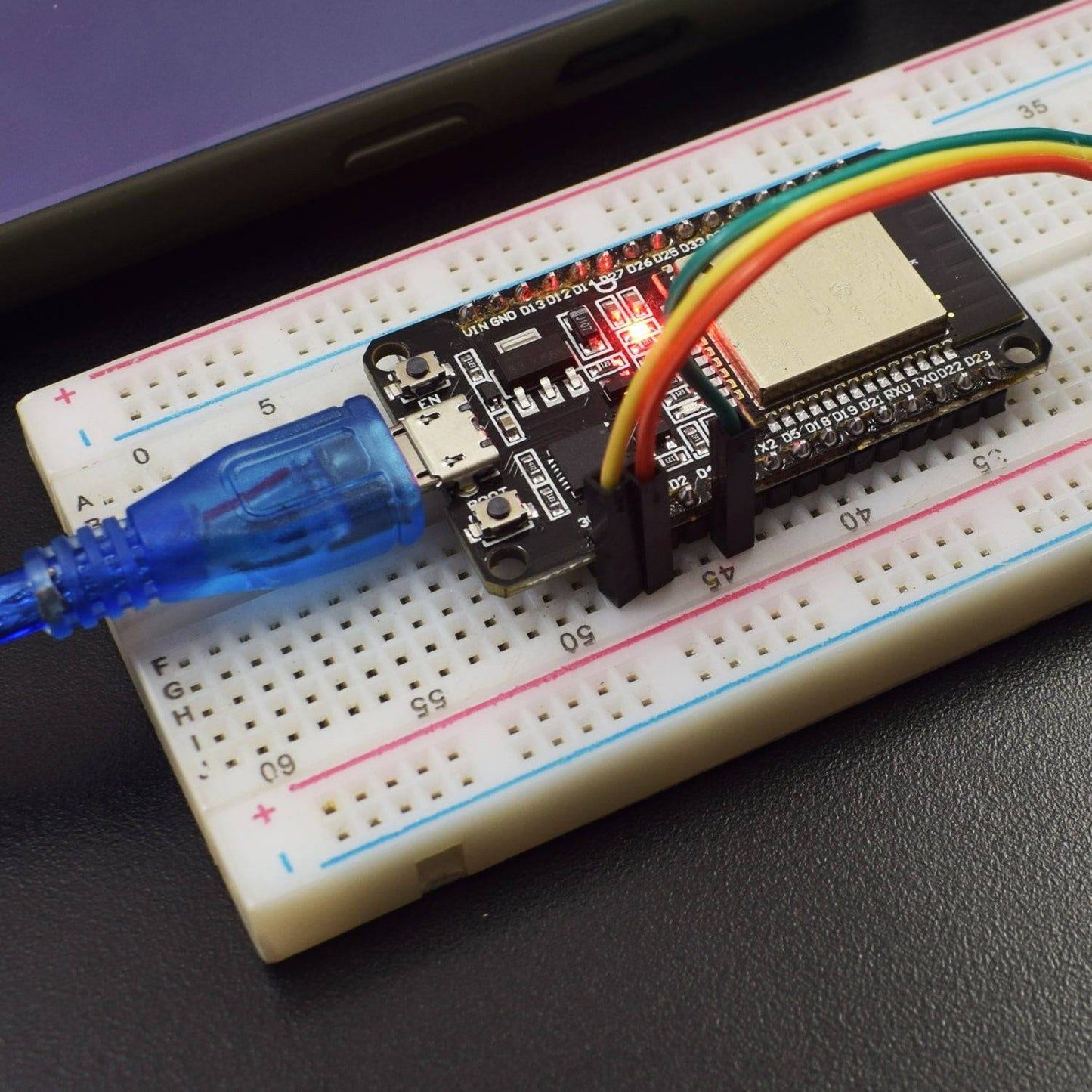
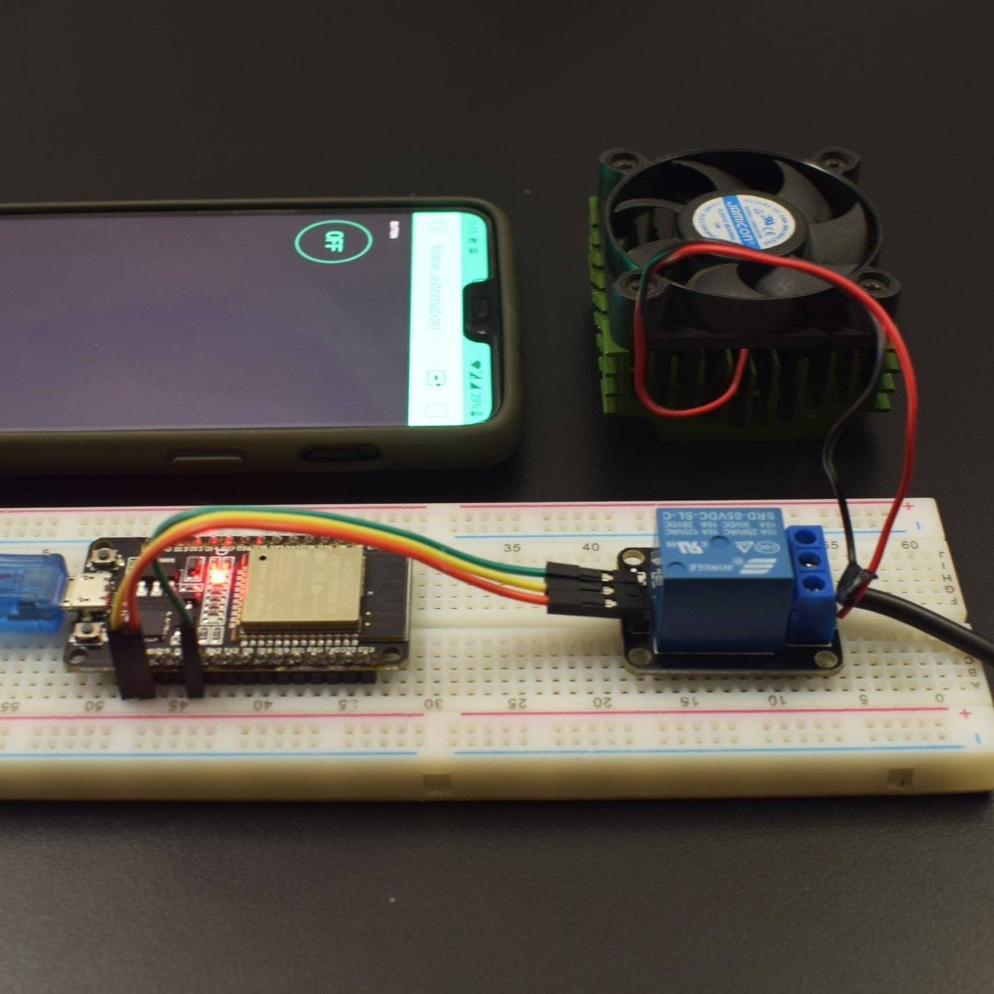
CIRCUIT CONNECTION
- Connect Vin pin of ESP32 with the positive terminal of the battery.
- Connect one GND pin of Node MCU with the negative terminal of the battery.
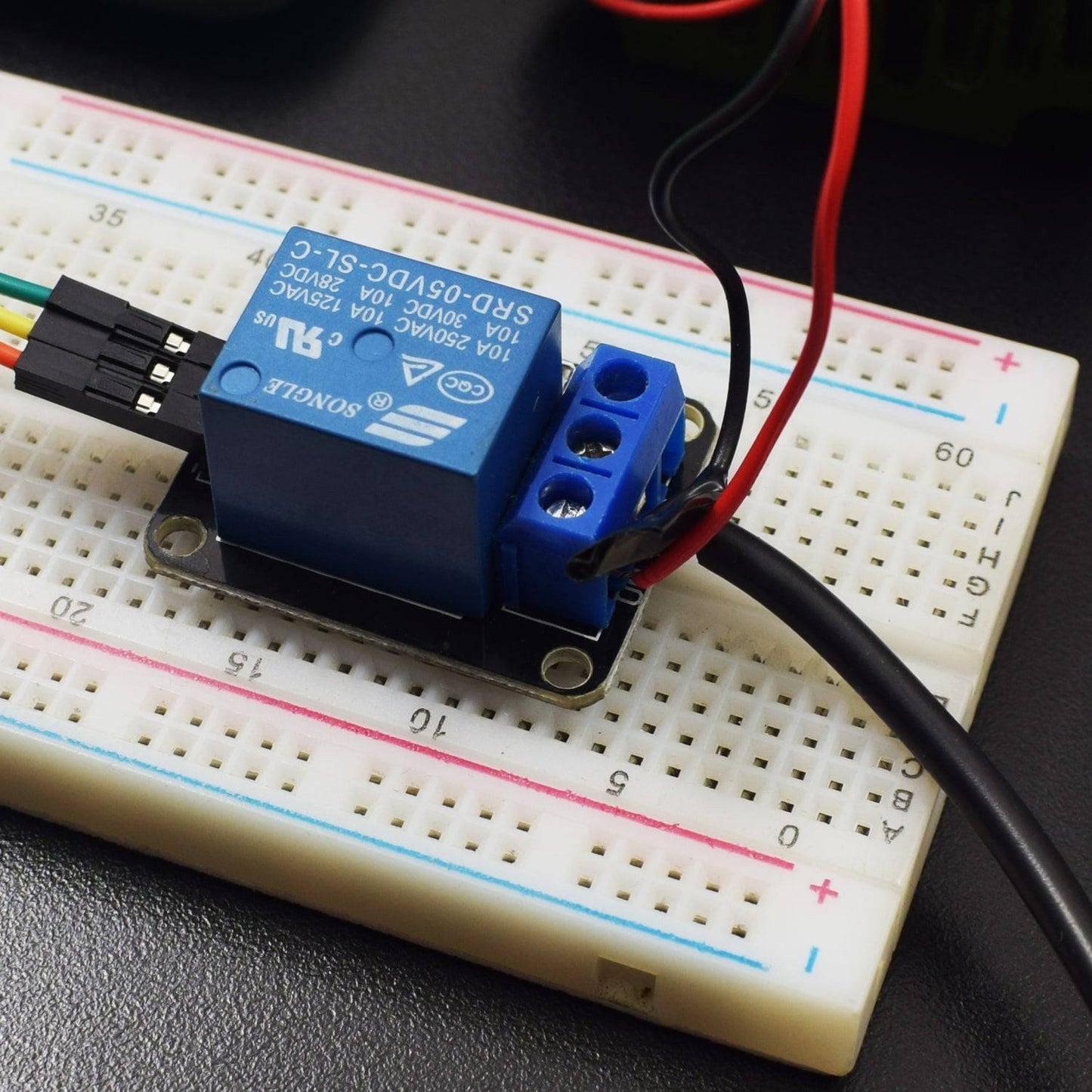
- Connect VCC pin of relay module to 3v3 pin of ESP32.
- Connect the GND pin of the relay module to the GND of ESP32.
- Connect the input pin of the relay module to pin D4 on ESP32.
- Connect the positive wire of 12V adapter to COM port in the relay module.
- Connect the positive wire of fan to NO port in the relay module.
- Connect negative wire of adapter to negative wire of fan.

CODE
NOTE: Press Boot key placed on board to avoid Packet header TimeOut Error.
(One of the ways to solve this is holding-down the “BOOT/FLASH” button in your ESP32 board while uploading a new sketch at the same time)
or
To make your ESP32 board go into flashing/uploading mode automatically, you can connect a 10 uF electrolytic capacitor between the EN pin and GND.
You may want to test this setup first on a breadboard to make sure it works for your ESP32 development board.

Note: electrolytic capacitors have polarity. The white/grey stripe indicates the negative lead.
If it works, then you can solder the 10 uF electrolytic capacitor to the board. Since the EN and GND pins are far apart from each other, you can simply connect the capacitor between the EN and the GND of the ESP32 chip as shown in the schematic diagram below:

Click to see the code
https://drive.google.com/open?id=116lnSMFPPs3aWm0t-WezFU-aSUvTl5AO
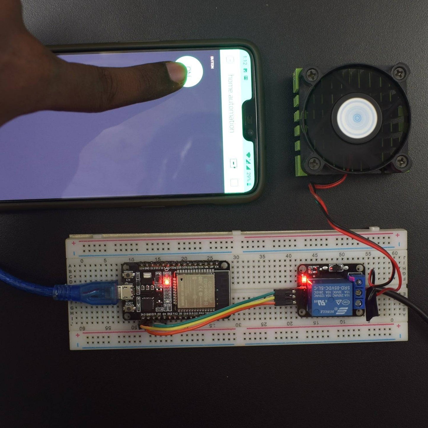
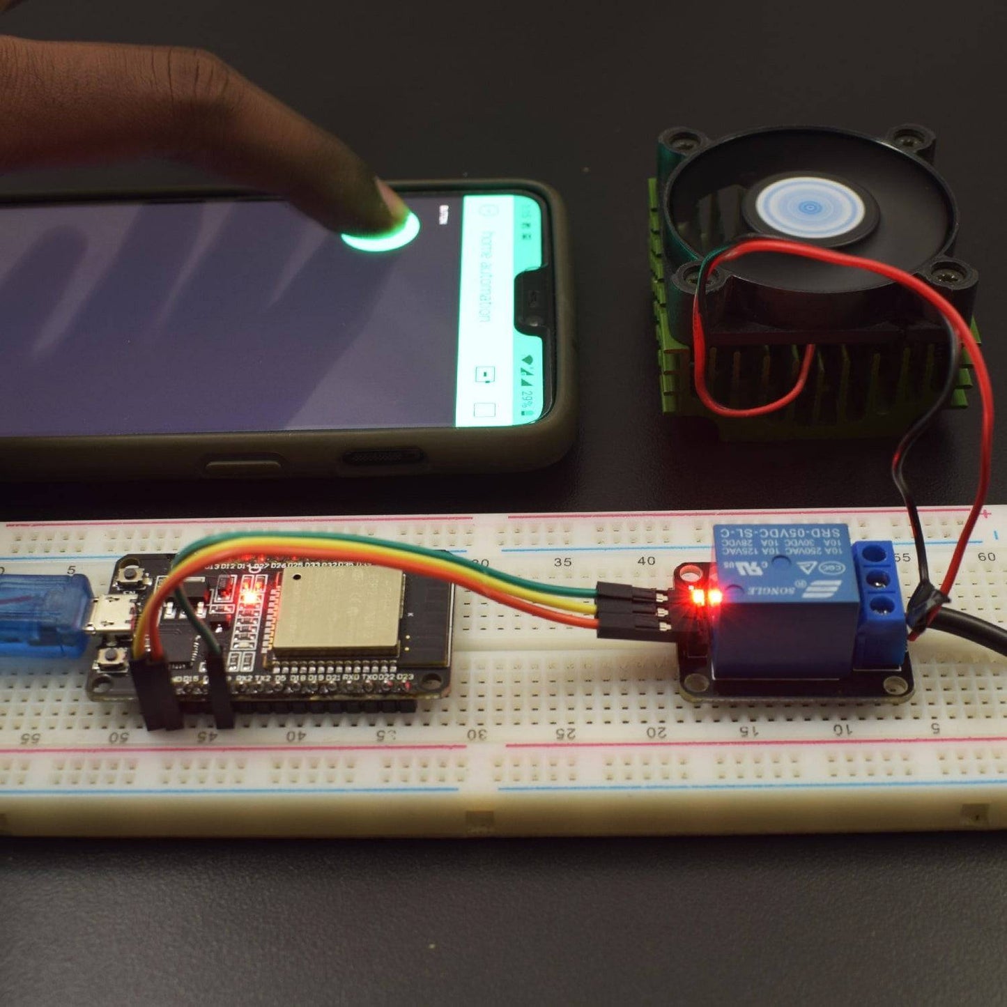
WORKING AND OUTPUT
Welcome to the ESP32 Based project.
In this project, we use the BLYNK app to access the Wifi SSID point created by ESP32.
In the app, the ON/OFF switch controls the motion of the fan directly.

Click to watch the tutorial
For more tutorials subscribe our channel REES52 on YouTube