


vendor-unknown
Make a Flip Flop Led circuit using BC547 transistor and led - KT577
Make a Flip Flop Led circuit using BC547 transistor and led - KT577
SKU:KT577
Low stock: 3 left
Couldn't load pickup availability
- For Bulk Order Click Here
- Need Customer Support?
- Free Delivery Above 999/-
Note: In case you receive a damaged or faulty product, please return it in the original box with all foam and packaging. Returns will not be accepted if further damage occurs due to improper packing.
For refund/return/replacement, call us at +91 95995 94520 or email us at support@rees52.com
Delivery Time
Delivery Time
- Delivery time with the Express Shipping option is 2-3 working days, and with the Standard Shipping option is 5-6 working days. It varies based on location, reliant on courier services.
- Delivery time if the order item is on Preorder Status is 15-20 working days.
COD (Cash on Delivery)
COD (Cash on Delivery)
- For COD you have to pay extra charges of Rs 350/- before the shipment. (We will share the company QR Code, UPI ID or Account details for the same)
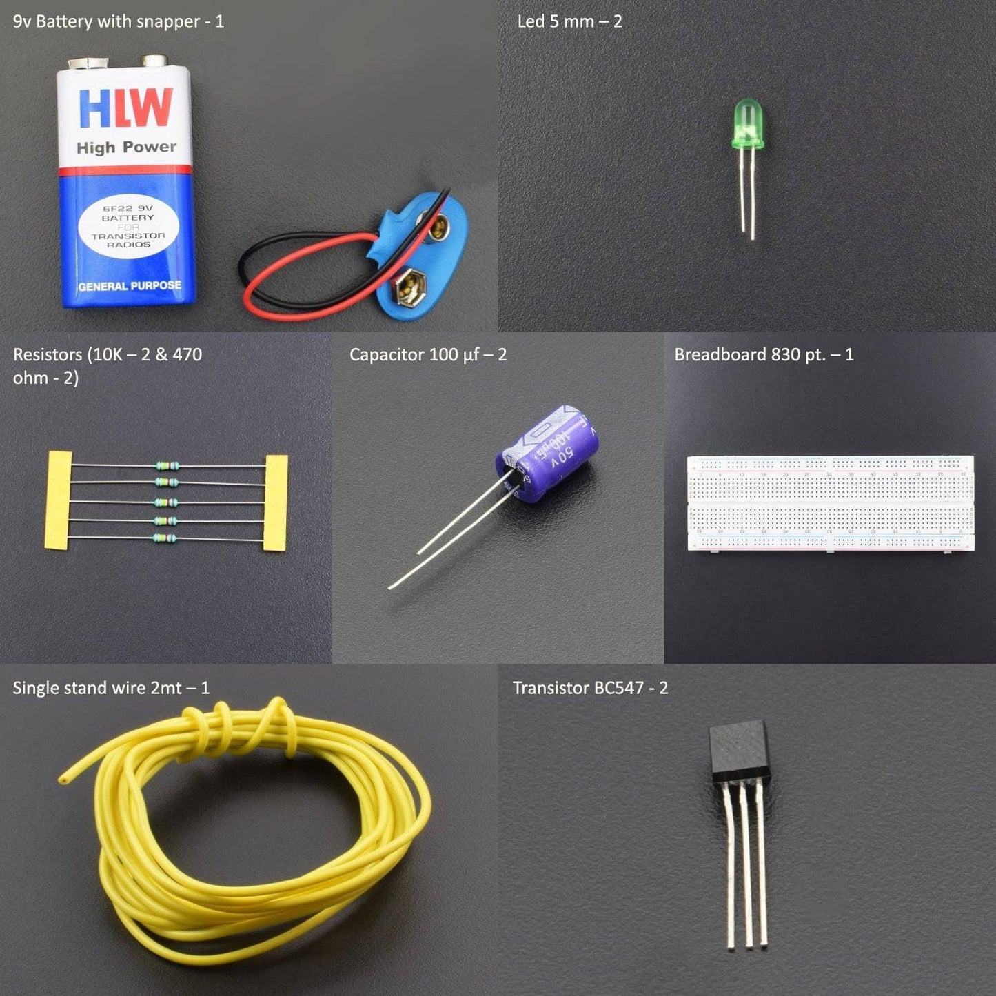


KIT INCLUDES :
- Resistors (10K – 2 & 470 ohm - 2)
- Capacitor 100 µf – 2
- Breadboard 830 pt. – 1
- Transistor BC547 - 2
- Single stand wire 2mt – 1
- Led 5 mm – 4
- 9v Battery - 1
- Battery snapper – 1
Introduction
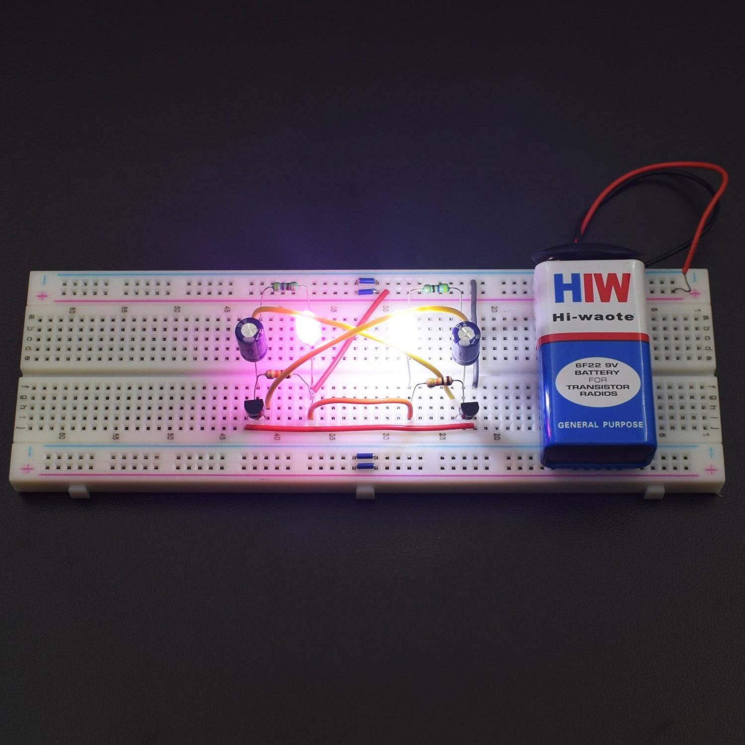
In this video we will make a Flip Flop Led Flashing circuit using Resistors and Capacitors. This circuit is actually an astable multi-vibrator which starts blinking leds one by one when power is applied. This circuit can be operated with any 6-12v voltage source. You can also operate the circuit by changing the values of the current limiting resistors R1 and R4 to 390 ohms
HARDWARE REQUIRED
- Resistors (10K – 2 & 470 ohm - 2)
- Capacitor 100 µf – 2
- Breadboard 830 pt. – 1
- Transistor BC547 - 2
- Single stand wire 2mt – 1
- Led 5 mm – 4
- 9v Battery - 1
- Battery snapper – 1
SPECIFICATIONS
Led

Capacitor

BC547 Transistor
![]()
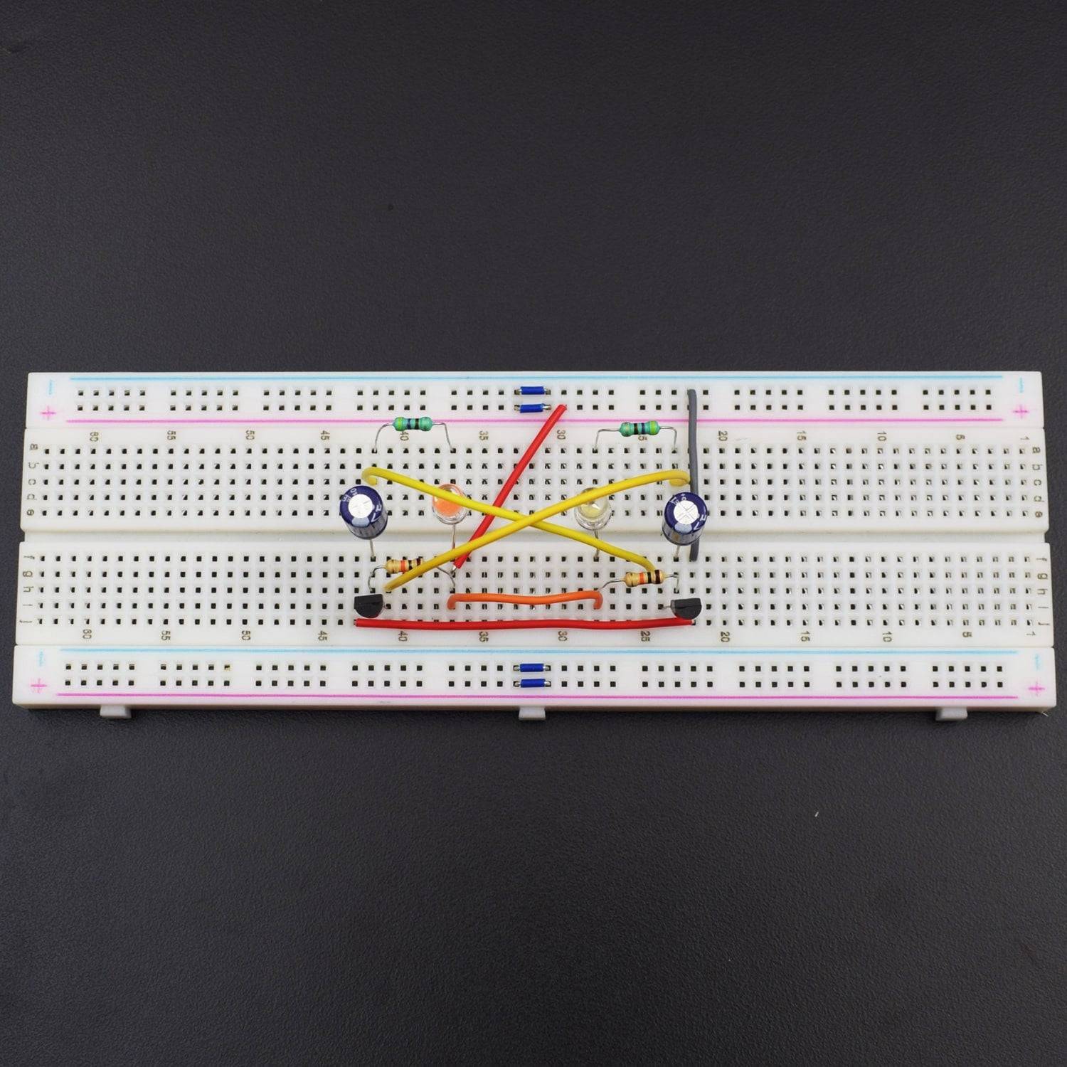
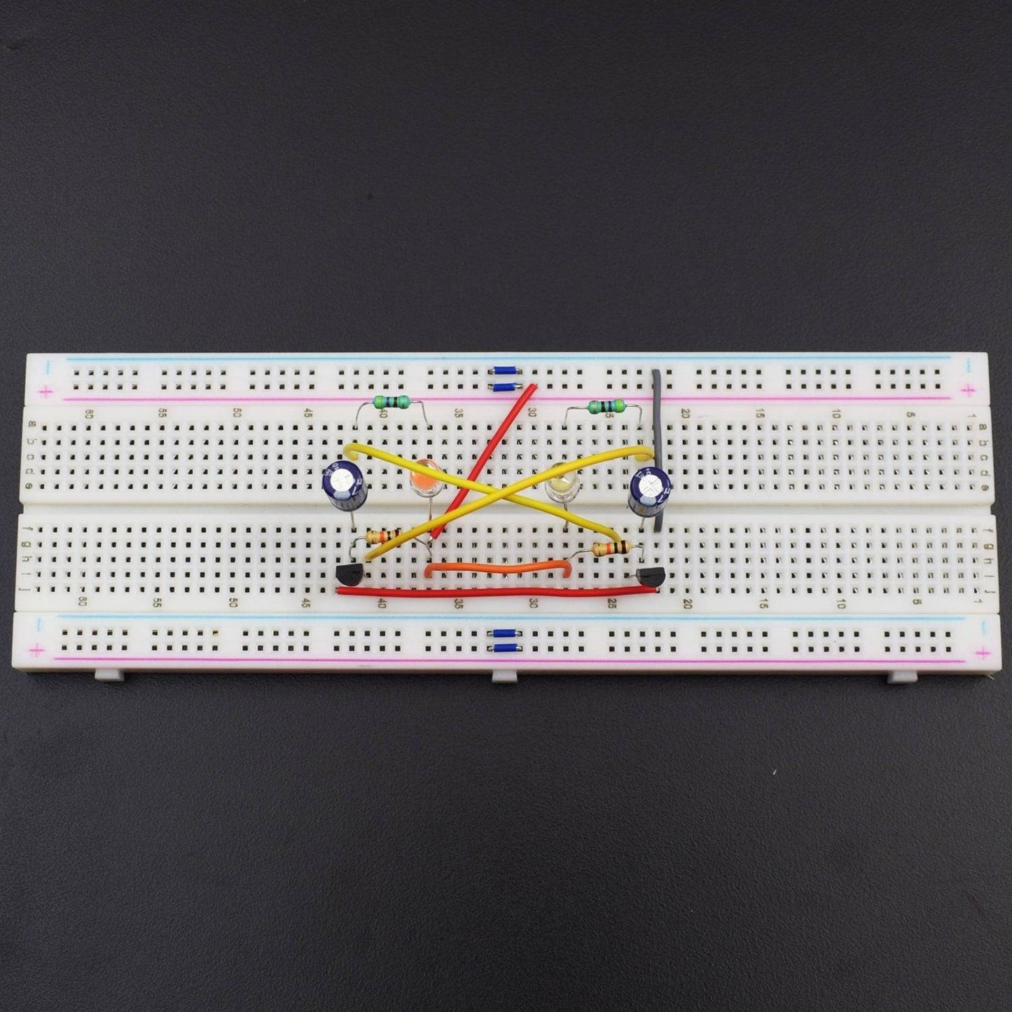
CIRCUIT CONNECTION
- Attach both transistor Q1 and Q2 to the breadboard
- Connect 10K Resistor R3 to the Base terminal of the Transistor Q1 and the other leg of resistor to the different column for further connection.
- Connect Another 10K Resistor R4 to the transistor Q2 similarly.
- Connect both the rest terminals of 10K resistor with hook up wire.
- Connect negative leg of the 100uf capacitor C1 to the base terminal of transistor Q1.
- Similarly connect the another 100uf capacitor to transistor Q2.
- Connect 470-ohm Resistor R1 to the transistor Q1and the other terminal to the different column.
- Connect 470-ohm resistor R2 to the transistor Q2 similarly.
- Connect positive Terminal of Led 1 to the Rest terminal of 10k Resistor R3 which is directly connected to the transistor Q1.
- Connect the Led 2 Similarly.
- Connect Emitter pin of Transistor Q1 to the Collector pin of Transistor Q2.
- Connect collector pin of transistor Q1 to the positive terminal of 100uf capacitor C2.
- Connect Emitter pin of Transistor Q2 to the positive leg of 100 uf Capacitor C1.
- Now connect the positive terminal of battery to the positive terminal of led 2 and the negative terminal to collector pin of transistor Q1.

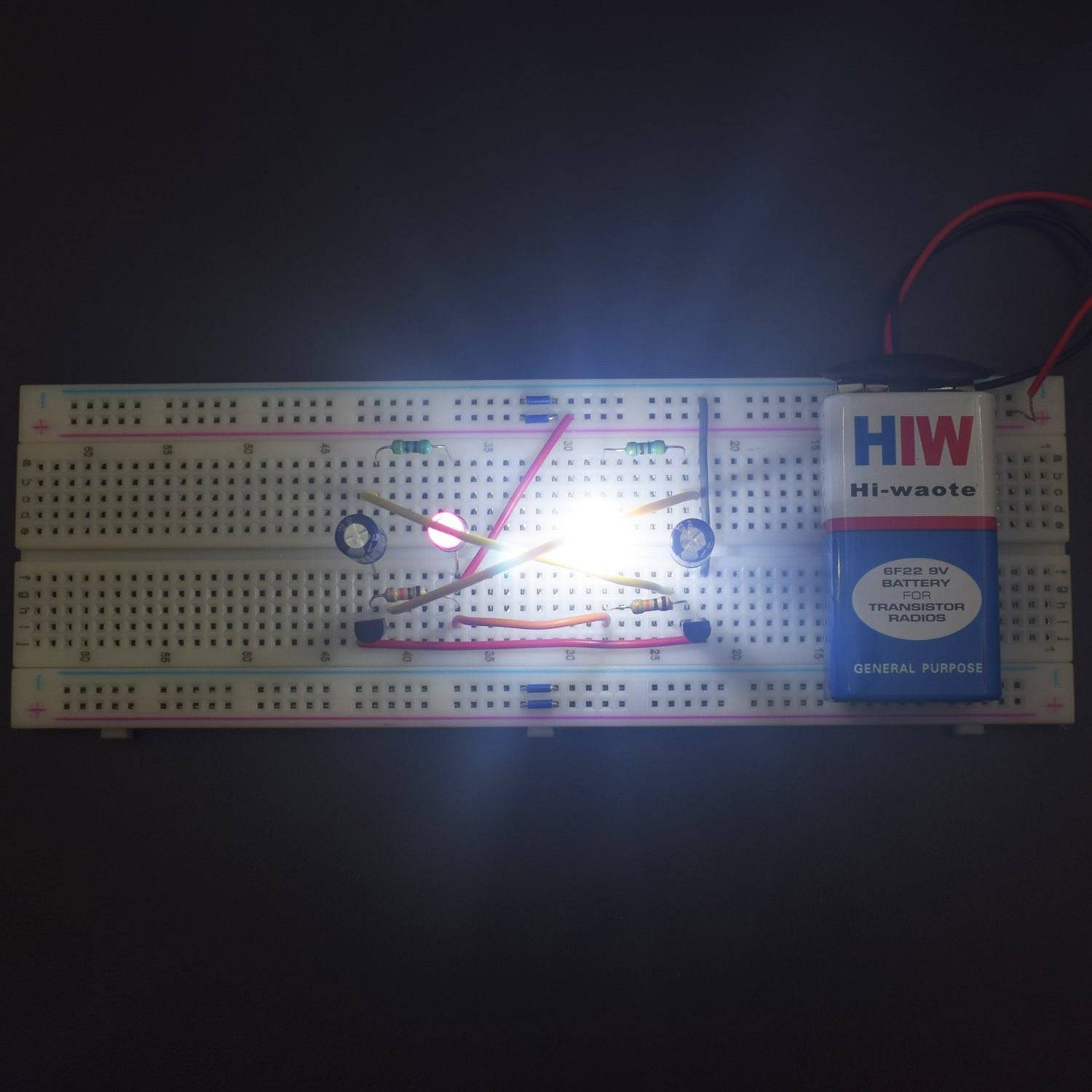
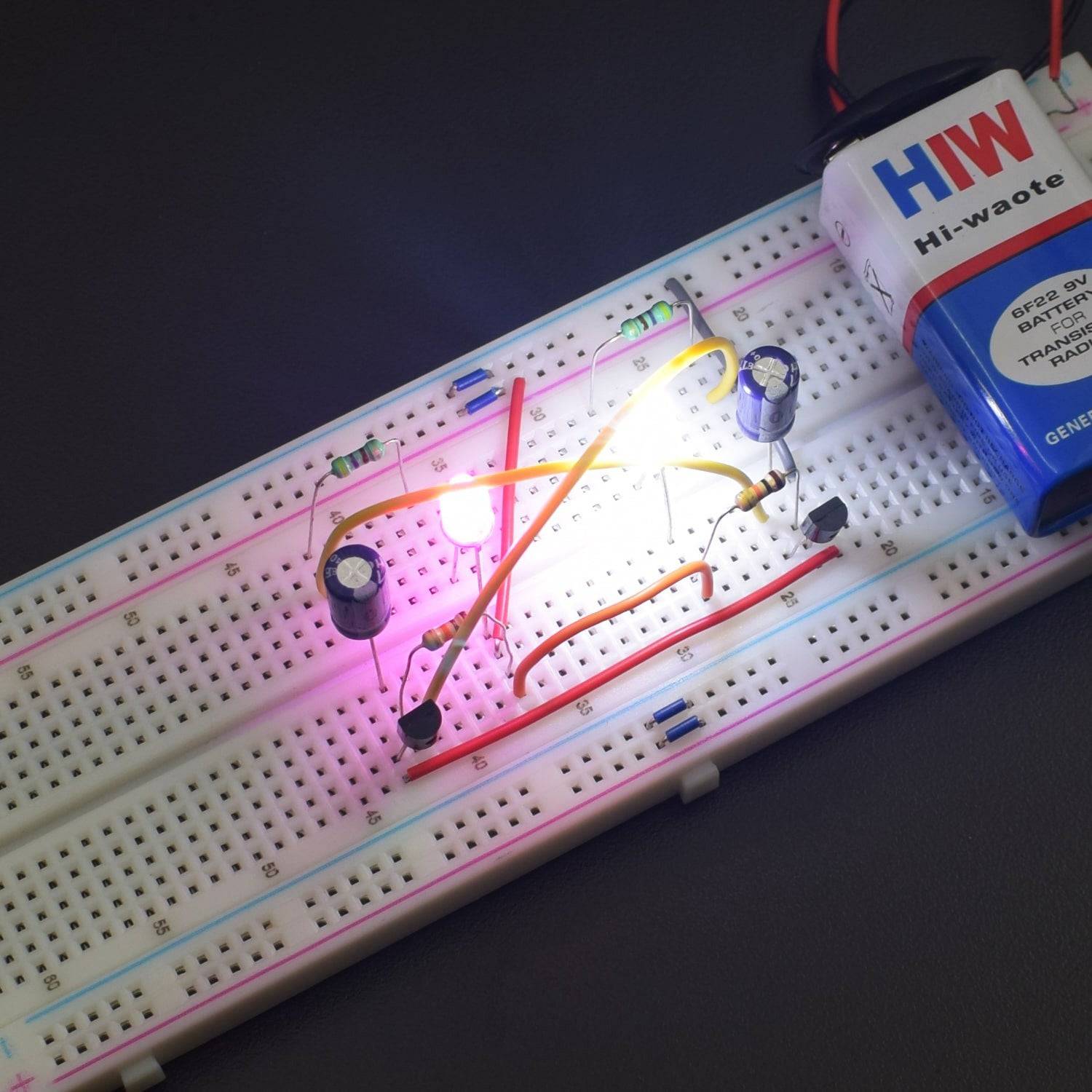
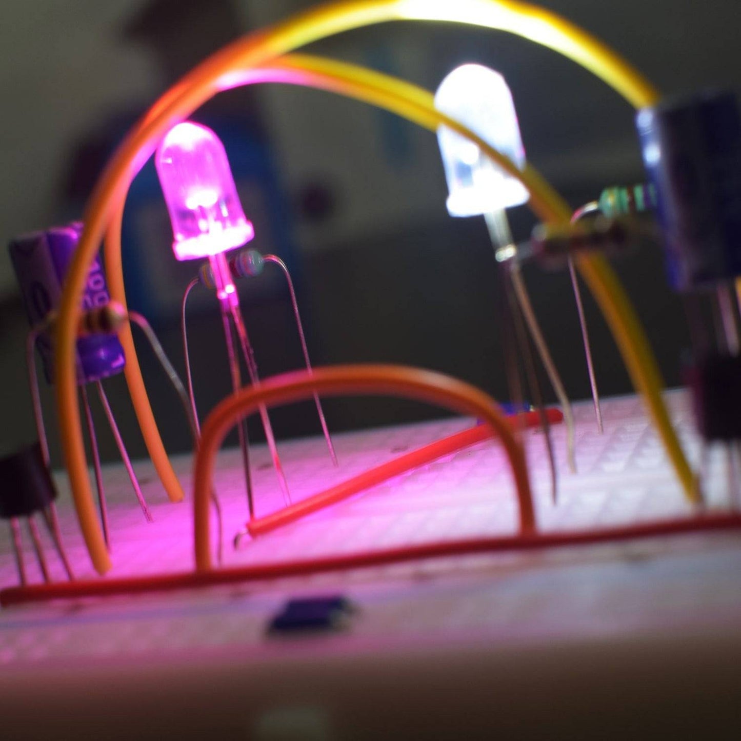
WORKING AND OUTPUT
After connecting the battery. you can see both the leds will light up in flip flop mode due to the delay created for each of the cycle. When the capacitor and resistors are made equal, each led flashes for the same length of time.

Click to watch the tutorial
For more tutorials subscribe our channel REES52 on YouTube