


vendor-unknown
Make a Flame Detection System using Flame Sensor Module - KT617
Make a Flame Detection System using Flame Sensor Module - KT617
SKU:KT617
997 in stock
Couldn't load pickup availability
- For Bulk Order Click Here
- Need Customer Support?
- Free Delivery Above 999/-
Note: In case you receive a damaged or faulty product, please return it in the original box with all foam and packaging. Returns will not be accepted if further damage occurs due to improper packing.
If you order a product that is currently in Preorder, and the price of that item increases in the future, you will be required to pay the difference in price.
For refund/return/replacement, call us at +91 95995 94520 or email us at support@rees52.com
Delivery Time
Delivery Time
- Delivery time with the Express Shipping option is 2-3 working days, and with the Standard Shipping option is 5-6 working days. It varies based on location, reliant on courier services.
- Delivery time if the order item is on Preorder Status is 15-20 working days.
COD (Cash on Delivery)
COD (Cash on Delivery)
- For COD you have to pay extra charges of Rs 350/- before the shipment. (We will share the company QR Code, UPI ID or Account details for the same)

Hardware Required
- Arduino Uno With USB Cable - 1
- Flame Detection Sensor Module - 1
- Peizo Buzzer Module - 1
- 5V 1 Channel Relay Module - 1
- 3-6V DC Mini Horizontal Submersible Pump - 1
- 9V battery - 2
- Snapper With DC Jack - 1
- Snapper - 1
- 400 Point Bread board - 1
- Jumper Wire (male to male) - 40 pcs
- Jumper Wire (male to female) - 40 pcs
Introduction
In this project, we will make the flame detection system which will control flame using water pump for water supply. Such a project can be enhanced using various other components.
HARDWARE REQUIRED
- Arduino Uno With USB Cable - 1
- Flame Detection Sensor Module - 1
- Peizo Buzzer Module - 1
- 5V 1 Channel Relay Module - 1
- 3-6V DC Mini Horizontal Submersible Pump - 1
- 9V battery - 2
- Snapper With DC Jack - 1
- Snapper - 1
- 400 Point Bread board - 1
- Jumper Wire (male to male) - 40 pcs
- Jumper Wire (male to female) - 40 pcs
SOFTWARE REQUIRED
Arduino IDE 1.8.5 (programmable platform for Arduino)
Click To Download :https://www.arduino.cc/en/Main/Software
SPECIFICATIONS
Flame Sensor Module
This sensor detects for flame wavelengths between 760 nm to 1100 nm infrared and is most sensitive. The module has two outputs:
- AO - analog output, real-time output voltage signal on the thermal resistance
- DO, when the temperature reaches a certain threshold, the output high and low signal threshold adjustable via potentiometer; 60 degree detection sensor.
- LM393 comparator chip
- Detection Range: 760 nm to 1100 nm
- Operating Voltage: 3.3 V to 5 V
- Maximum Output Current: 15 mA
- Digital Outputs: 0 and 1
- Detection Angle: about 60 degrees
- Adjustable sensitivity via potentiometer
- LED lights indicators: power (red) and digital switching O/P (green)
- Please keep a distance with flame, high temperature maybe burn out the sensor module.

Piezo Buzzer Module
Arduino Passive Piezoelectric Buzzer Module can produce a range of sound tones depending on the input frequency. It consists of a passive piezoelectric buzzer, it can generate tones between 1.5 to 2.5 kHz by switching it on and off at different frequencies either using delays or PWM.
- Operating Voltage: 1.5~15V DC
- Tone Generation Range: 1.5~2.5kHz
- Dimensions: 18.5mm*15mm

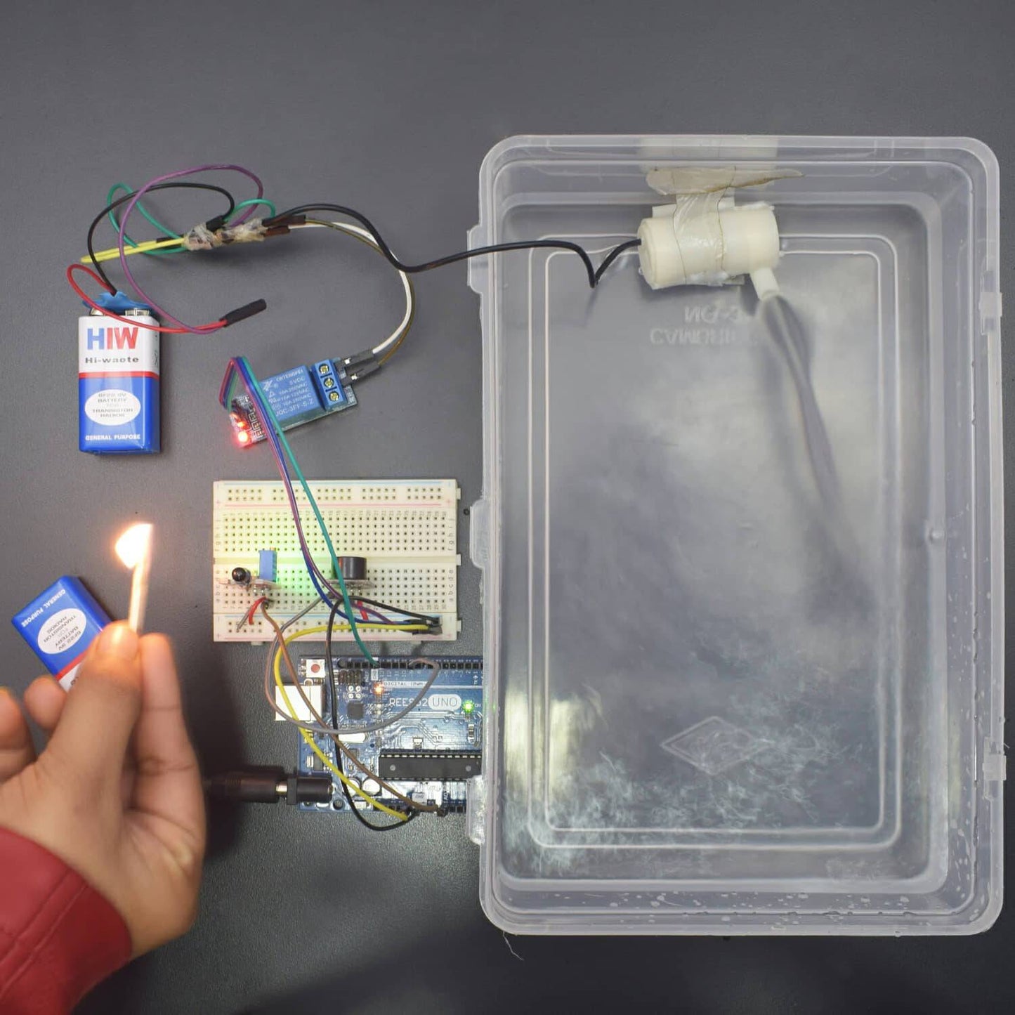
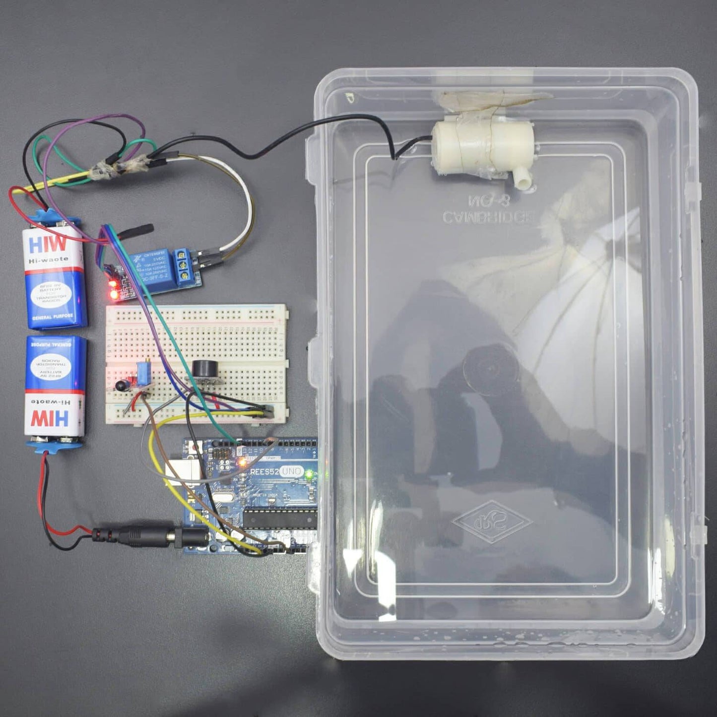
CIRCUIT CONNECTION
- Attach Flame Sensor and Buzzer on the Breadboard.
- Connect GND of Arduino Uno with Breadboard for further GND connections.
- Connect Pin 5V of Arduino Uno with Breadboard for further 5V power supply connections.
- Connect VCC of Flame Sensor with Pin 3.3V of Arduino Uno.
- Connect GND of Flame Sensor with GND rail of Breadboard.
- Connect Pin A0 of Flame Sensor with Analog Pin A0 of Arduino Uno.
- Connect GND of Buzzer with GND rail of Breadboard.
- Connect VCC of Buzzer with 5V rail of Breadboard.
- Connect Pin Signal of Buzzer with Digital Pin 9 of Arduino Uno.
- Connect VCC of Relay with 5V rail of Breadboard.
- Connect GND of Relay with GND rail of Breadboard.
- Connect Pin Signal of Relay with Digital Pin 13 of Arduino Uno.
- Connect Pin NC of Relay with one terminal of Water Pump Motor.
- Connect another terminal of Water Pump Motor with one terminal of Battery (Black wire).
- Connect Pin C (Common) of Relay with another terminal of Battery (red wire).

CODE
https://drive.google.com/open?id=1eqrEo4aML9iG_kg_i1M6NdrVX6bgfpa
WORKING
Welcome to the Arduino Based Project which consists of Flame Sensor and Relay Module. The basic functionality of Flame Sensor is being described here.When fire burns it emits a small amount of Infra-red light, this light will be received by the Photodiode (IR receiver) on the sensor module. Then we use an Op-Amp to check for change in voltage across the IR Receiver, so that if a fire is detected the output pin (DO) will give 0V(LOW) and if the is no fire the output pin will be 5V(HIGH). The flame detector has functions of collecting, processing input signals and output control signals.
Also, when Arduino checks the logic level on the output pin of the sensor and performs further tasks such as activating the buzzer and LED, sending an alert by turning on the Water Pump motor. This system acts as firefighting bot which is activated when Fire is being detected by module.