

vendor-unknown
Make a ECG Testing Device using ECG Sensor Module interfacing with Arduino Uno - KT991
Make a ECG Testing Device using ECG Sensor Module interfacing with Arduino Uno - KT991
SKU:KT991
999 in stock
Couldn't load pickup availability
- For Bulk Order Click Here
- Need Customer Support?
- Free Delivery Above 999/-
Note: In case you receive a damaged or faulty product, please return it in the original box with all foam and packaging. Returns will not be accepted if further damage occurs due to improper packing.
If you order a product that is currently in Preorder, and the price of that item increases in the future, you will be required to pay the difference in price.
For refund/return/replacement, call us at +91 95995 94520 or email us at support@rees52.com
Delivery Time
Delivery Time
- Delivery time with the Express Shipping option is 2-3 working days, and with the Standard Shipping option is 5-6 working days. It varies based on location, reliant on courier services.
- Delivery time if the order item is on Preorder Status is 15-20 working days.
COD (Cash on Delivery)
COD (Cash on Delivery)
- For COD you have to pay extra charges of Rs 350/- before the shipment. (We will share the company QR Code, UPI ID or Account details for the same)

In this project, we have built an Arduino based heartbeat monitor which counts the number of heartbeats in a minute.
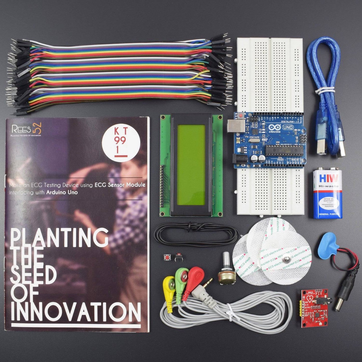
KIT INCLUDED
- Arduino with USB Cable - 1
- ECG heart ECG Monitoring Sensor Module Kit -1
- 20*4 LCD Display - 1
- Push button - 2
- 9v Battery - 1
- battery snapper - 1
- Single stand wire 2 mt – 1
- Potentiometer 10k – 1
- Jumper wires male to male– 40 pieces
- Jumper wires male to female – 40 pieces
- 830 Pt. Breadboard -1
Heart rate, body temperature, and blood pressure monitoring are very important parameters of the human body. Doctors use various kind of medical apparatus like a thermometer for checking fever or body temperature, BP monitor for blood pressure measurement and heart rate monitor for heart rate measurement. In this project, we have built an Arduino based heartbeat monitor which counts the number of heartbeats in a minute. Here we have used a heartbeat sensor module which senses the heartbeat upon putting a finger on the sensor.
HARDWARE REQUIRED
- Arduino with USB Cable - 1
- ECG heart ECG Monitoring Sensor Module Kit -1
- 20*4 LCD Display - 1
- Push button - 2
- 9v Battery - 1
- battery snapper - 1
- Single stand wire 2 mt – 1
- Potentiometer 10k – 1
- Jumper wires male to male– 40 pieces
- Jumper wires male to female – 40 pieces
- 830 Pt. Breadboard -1
SOFTWARE REQUIRED
Arduino IDE 1.8.5 (programmable platform for Arduino)
Click To Download :https://www.arduino.cc/en/Main/Software


SPECIFICATIONS
Heartbeat sensor (ECG Module)
- Supply current: 170 µA (typical)
- Supply Voltage : 2.0 V to 3.6V
- Operating Temperature Range −40°C to +85°C
- ESD Rating :Human Body Model (HBM) 8 kV ,Charged Device Model (FICDM) 1.25 kV ,Machine Model (MM) 200 V
- 2-pole adjustable high-pass filter
- Fully integrated single-lead ECG front end
- Accepts up to ±300 mV of half-cell potential
- High signal gain (G = 100) with dc blocking capabilities
- Two or three electrode configurations
20*4 LCD Display
- Standard 20*4 Character LCD
- Built in Controller (HD44780 or equivalent)
- +3.3V Power Supply
- Backlight Included
CAUTION
- The LCD panel is made by glass. Any mechanical shock (e.g. dropping from high place) will damage the LCD module.
- Do not add excessive force on the surface of the display, which may cause the Display colour change abnormally.
- The polarizer on the LCD is easily get scratched. If possible, do not remove the LCD protective film until the last step of installation.
- Never attempt to disassemble or rework the LCD module.
- Only Clean the LCD with Isopropyl Alcohol or Ethyl Alcohol. Other solvents (eg.water) may damage the LCD.
- When mounting the LCD module, make sure that it is free form twisting, warping and distortion.
- Ensure to provide enough space (with cushion) between case and LCD panel to prevent external force adding on it, or it may cause damage to the LCD or degrade the display result.
- Only hold the LCD module by its side. Never hold LCD module by add force on the heat seal on TAB.
- Never add force to component of the LCD module. It may cause invisible damage or degrade of the reliability.
- LCD module could be easily damaged by static electricity. Be careful to maintain an optimum anti-static work environment to protect the LCD module.
- When peeling off the protective film from LCD, static charge may cause abnormal display pattern. It is normal and will resume to normal in a short while.
- Never operate the LCD module exceed the absolute maximum ratings.
- Keep the signal line as short as possible to prevent noisy signal applying to LCD module.
- Never apply signal to the LCD module without power supply.
PIN DESCRIPTION
20*4 LCD Display


Symbol |
External Connection |
Function |
VSS |
Power Supply |
Signal GROUND for lcm |
VDD |
POWER SUPPLY for logic lcm |
|
V0 |
Contrast Adjust |
|
RS |
MPU |
Register Select Signal |
RW |
MPU |
Read/Write Select Signal |
E |
MPU |
Operation Enable Signal |
DB0~DB3 |
MPU |
Four Low order bidirectional three state bus lines. Used for data transfer between the MPU and LCM. These four are not used between 4 Bit operations. |
DB4~DB7 |
MPU |
Four high order bidirectional Three state bus lines used for data transfer between the MPU |
A |
LED BKL power Supply |
Power Supply for BKL |
K |


CIRCUIT CONNECTION


Circuit of heartbeat monitor is shown below, which contains arduino Uno, heart beat sensor module, reset button and LCD. Arduino controls whole the process of system like reading pulses form Heart beat sensor module, calculating heart rate and sending this data to LCD. We can set the sensitivity of this sensor module by inbuilt potentiometer placed on this module.
- Heartbeat sensor module’s output pin is directly connected to pin 8 of Arduino.
- Vcc and GND of the heart beat module are connected to Vcc and GND.
- A 16x2 LCD is connected with Arduino in 4-bit mode. Control pin RS, RW and En are directly connected to arduino pin 12, GND and 11 respectively. And data pin D4-D7 is connected to pins 5, 4, 3 and 2 of arduino respectively.
- one push button is added for resetting reading and another is used to start the system for reading pulses. When we need to count heart rate, we press start button then arduino start counting pulses and also start counter for five seconds. This start push button is connected to pin 7 and reset push button is connected to pin 6 of arduino with respect to ground.
CODE
Click to download the code or copy the link
https://drive.google.com/open?id=1nnmqVKYw2WLuQvzPWvrp4NcHvTaEy63
WORKING
Working of this project is quite easy but a little calculation for calculating heart rate is required. There are several methods for calculating heart rate, but here we have read only five pulses. Then we have calculated total heart beat in a minute by applying the below formula:
Five_pusle_time=time2-time1;
Single_pulse_time= Five_pusle_time /5;
rate=60000/ Single_pulse_time;
where time1 is first pulse counter value
time2 is list pulse counter value
rate is final heart rate.


When first pulse comes, we start counter by using timer counter function in arduino that is millis();. And take first pulse counter value form millis();. Then we wait for five pulses. After getting five pulses we again take counter value in time2 and then we subtract time1 from time2 to take original time taken by five pulses. And then divide this time by 5 times for getting single pulse time. Now we have time for single pulse and we can easily find the pulse in one minute, dividing 600000 MS by single pulse time.
Rate= 600000/single pulse time
In this project we have used the Heart beat sensor module to detect Heart Beat. This sensor module contains an IR pair which actually detectheart beat from blood. Heart pumps the blood in body which is called heartbeat, when it happens the blood concentration in body changes. And we use this change to make a voltage or pulse electrically.
The ECG module comes with 3 electrode pads which should be placed as follows:
- Red to Right Arm
- Yellow to Left Arm
- Green to Right Leg