


vendor-unknown
Make a Dubstep (EDM) Player using Small Sound Sensor Module interfacing with Arduino Uno - KT653
Make a Dubstep (EDM) Player using Small Sound Sensor Module interfacing with Arduino Uno - KT653
SKU:KT653
1000 in stock
Couldn't load pickup availability
- For Bulk Order Click Here
- Need Customer Support?
- Free Delivery Above 999/-
Note: In case you receive a damaged or faulty product, please return it in the original box with all foam and packaging. Returns will not be accepted if further damage occurs due to improper packing.
If you order a product that is currently in Preorder, and the price of that item increases in the future, you will be required to pay the difference in price.
For refund/return/replacement, call us at +91 95995 94520 or email us at support@rees52.com
Delivery Time
Delivery Time
- Delivery time with the Express Shipping option is 2-3 working days, and with the Standard Shipping option is 5-6 working days. It varies based on location, reliant on courier services.
- Delivery time if the order item is on Preorder Status is 15-20 working days.
COD (Cash on Delivery)
COD (Cash on Delivery)
- For COD you have to pay extra charges of Rs 350/- before the shipment. (We will share the company QR Code, UPI ID or Account details for the same)
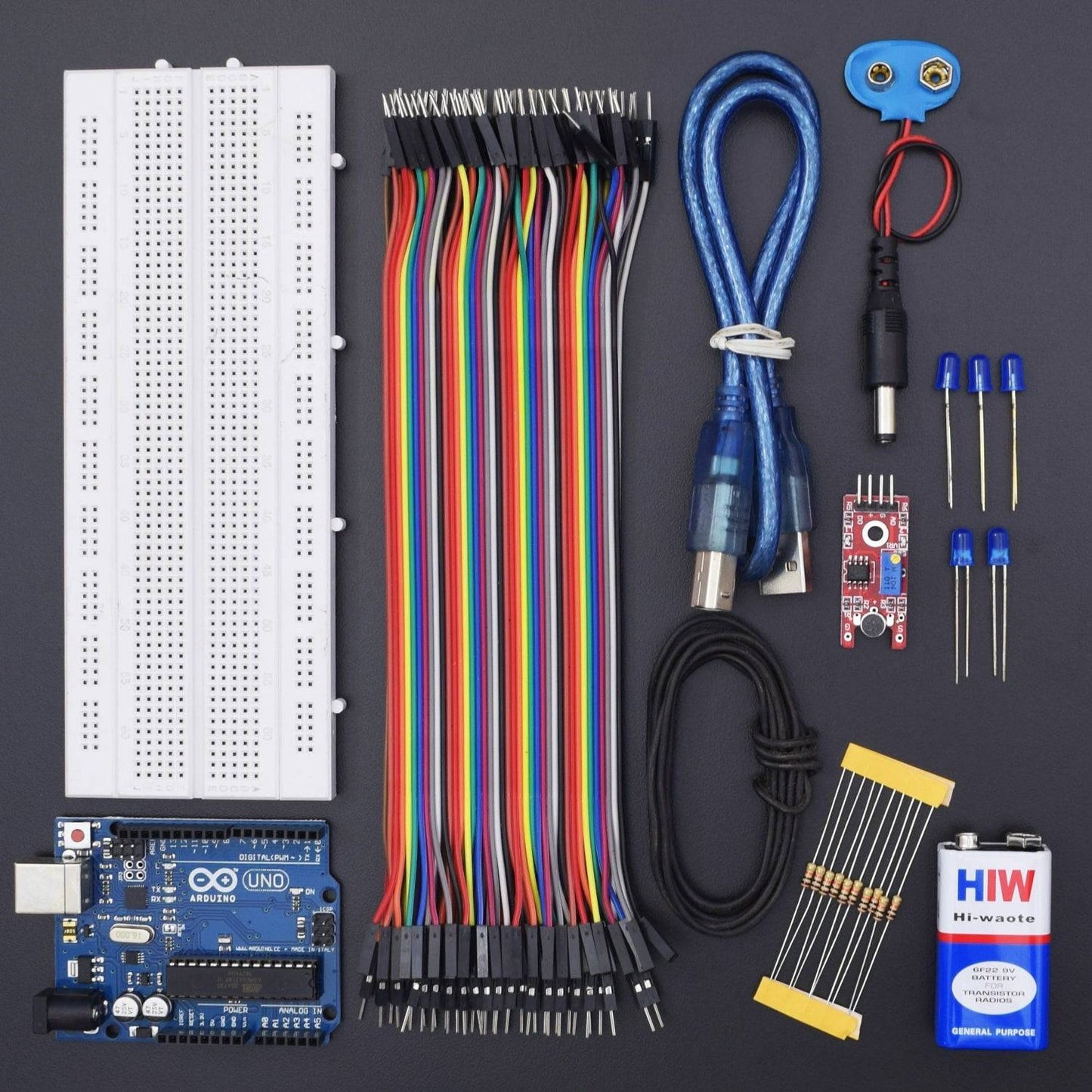
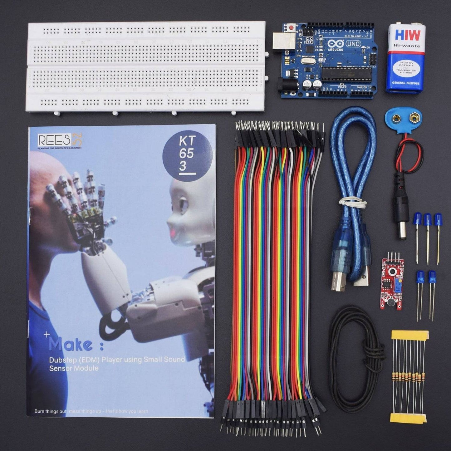

Hardware Required
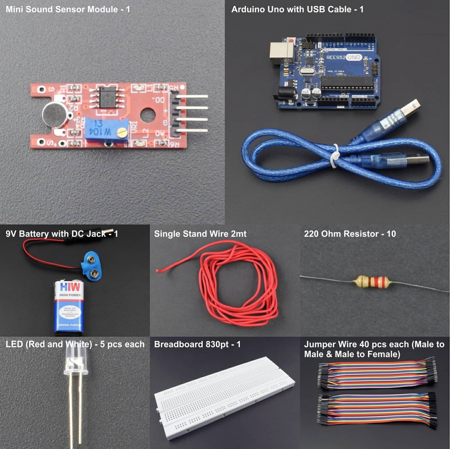
- Arduino Uno With USB Cable - 1
- Mini Sound Sensor Module - 1
- 9V Battery - 1
- Snapper With DC Jack - 1
- Red Led - 5
- White Led - 5
- 220 Ohm Resistance - 10
- Single Stand Wire 2 mt - 1
- Bread Board 840 Point - 1
- Jumper Wire (male to male) - 40 pcs
- Jumper Wire (male to female) - 40 pcs
Introduction
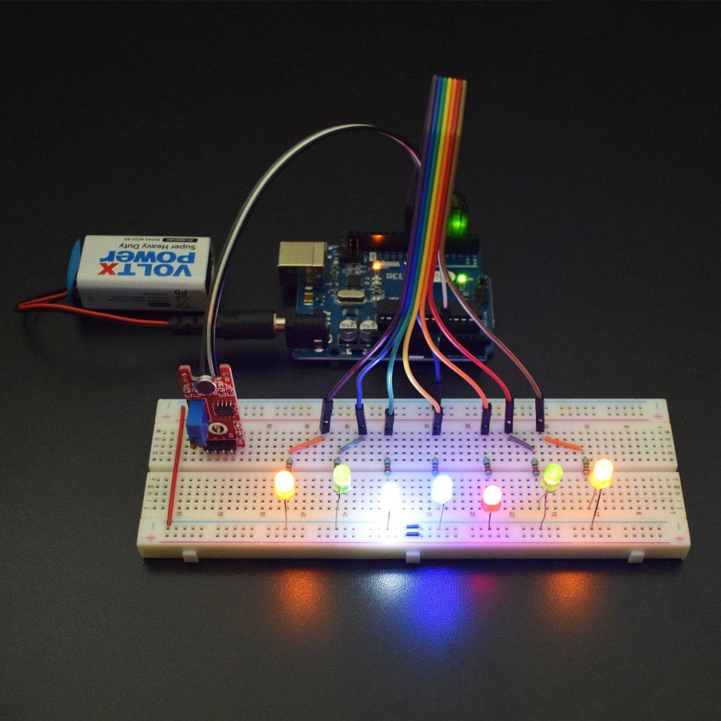
In this particular project, we will hook up the sound sensor to an array of LED lights which will beat with music, clapping or knocking. It can be used for controlling various other components.
HARDWARE REQUIRED
- Arduino Uno With USB Cable - 1
- Mini Sound Sensor Module - 1
- 9V Battery - 1
- Snapper With DC Jack - 1
- Red Led - 5
- White Led - 5
- 220 Ohm Resistance - 10
- Single Stand Wire 2mt - 1
- Bread Board 840 Point - 1
- Jumper Wire (male to male) - 40 pcs
- Jumper Wire (male to a female) - 40 pcs
SOFTWARE REQUIRED
Arduino IDE 1.8.5 (programmable platform for Arduino)
Click To Download: https://www.arduino.cc/en/Main/Software


SPECIFICATIONS
Mini Sound Sensor Module
The Small Sound Sensor Module features single channel signal output and uses low level output signals to control sound and light making this module perfect for audible alarm systems.
- Dimensions: 40x15x13mm
- Weight: 3.06g
- LM393 main chip
- Electric condenser microphone
- Features Single channel signal output
- Low level output signal used for sound control light
- Great module for sound alarm system
- Working voltage: DC 4-6V
- Interface definition:
- AO: analog output sensor
- GND: ground
- VCC: Power supply input range: 3V-24V.
- DO: Digital Output (comparator output)
- Two red LED indication: POWER and SENSOR. POWER: Power is off. SENSOR: When the microphone senses sound reaches a certain value, this LED light.

Arduino Uno

CIRCUIT CONNECTION
- Attach the 8 LEDs on the Breadboard.
- Connect GND of Arduino Uno with Breadboard for further GND connections.
- Connect the negative terminal of LEDs with GND rail of Breadboard via a 220Ω resistor.
- Connect the positive terminal of LED 1 with Digital Pin 3 of Arduino via 220Ω resistor.
- Connect the positive terminal of LED 2 with Digital Pin 4 of Arduino via 220Ω resistor.
- Connect the positive terminal of LED 3 with Digital Pin 5 of Arduino via 220Ω resistor.
- Connect the positive terminal of LED 4 with Digital Pin 6 of Arduino via 220Ω resistor.
- Connect the positive terminal of LED 5 with Digital Pin 7 of Arduino via 220Ω resistor.
- Connect the positive terminal of LED 6 with Digital Pin 8 of Arduino via 220Ω resistor.
- Connect the positive terminal of LED 7 with Digital Pin 9 of Arduino via 220Ω resistor.
- Connect GND of Small Sound Sensor with GND of Arduino.
- Connect VCC of Small Sound Sensor with Pin 5V of Arduino.
- Connect Pin D0 of Small Sound Sensor with Digital Pin 2 of Arduino.
- Connect Pin A0 of Small Sound Sensor with Analog Pin A0 of Arduino.

CODE
https://drive.google.com/open?id=1vsx7XmGi588NWBdz8xCb3cFzZahNM2iS
WORKING
Welcome to the Arduino Based Project which consists of Small sound sensor module and its basic functionality is being described here. The microphone sound sensor, as the name says, detects sound. It gives the approximate measurement of how loud a sound is.
After uploading the code, you can clap next to the sensor. If the LED is not lighting up, then you need to change the sensor sensitivity by rotating the potentiometer. Also, you can also adjust the sensitivity so that the LED follows the beat of certain music. Thus, add more LEDs for a more spectacular effect.