


vendor-unknown
Make a Door Bell using NE555 Timer IC - KT955
Make a Door Bell using NE555 Timer IC - KT955
SKU:KT955
998 in stock
Couldn't load pickup availability
- For Bulk Order Click Here
- Need Customer Support?
- Free Delivery Above 999/-
Note: In case you receive a damaged or faulty product, please return it in the original box with all foam and packaging. Returns will not be accepted if further damage occurs due to improper packing.
For refund/return/replacement, call us at +91 95991 22209 or mail us at support@rees52.com
Delivery Time
Delivery Time
- Delivery time with the Express Shipping option is 2-3 working days, and with the Standard Shipping option is 5-6 working days. It varies based on location, reliant on courier services.
- Delivery time if the order item is on Preorder Status is 15-20 working days.
COD (Cash on Delivery)
COD (Cash on Delivery)
- For COD you have to pay extra charges of Rs 350/- before the shipment. (We will share the company QR Code, UPI ID or Account details for the same)
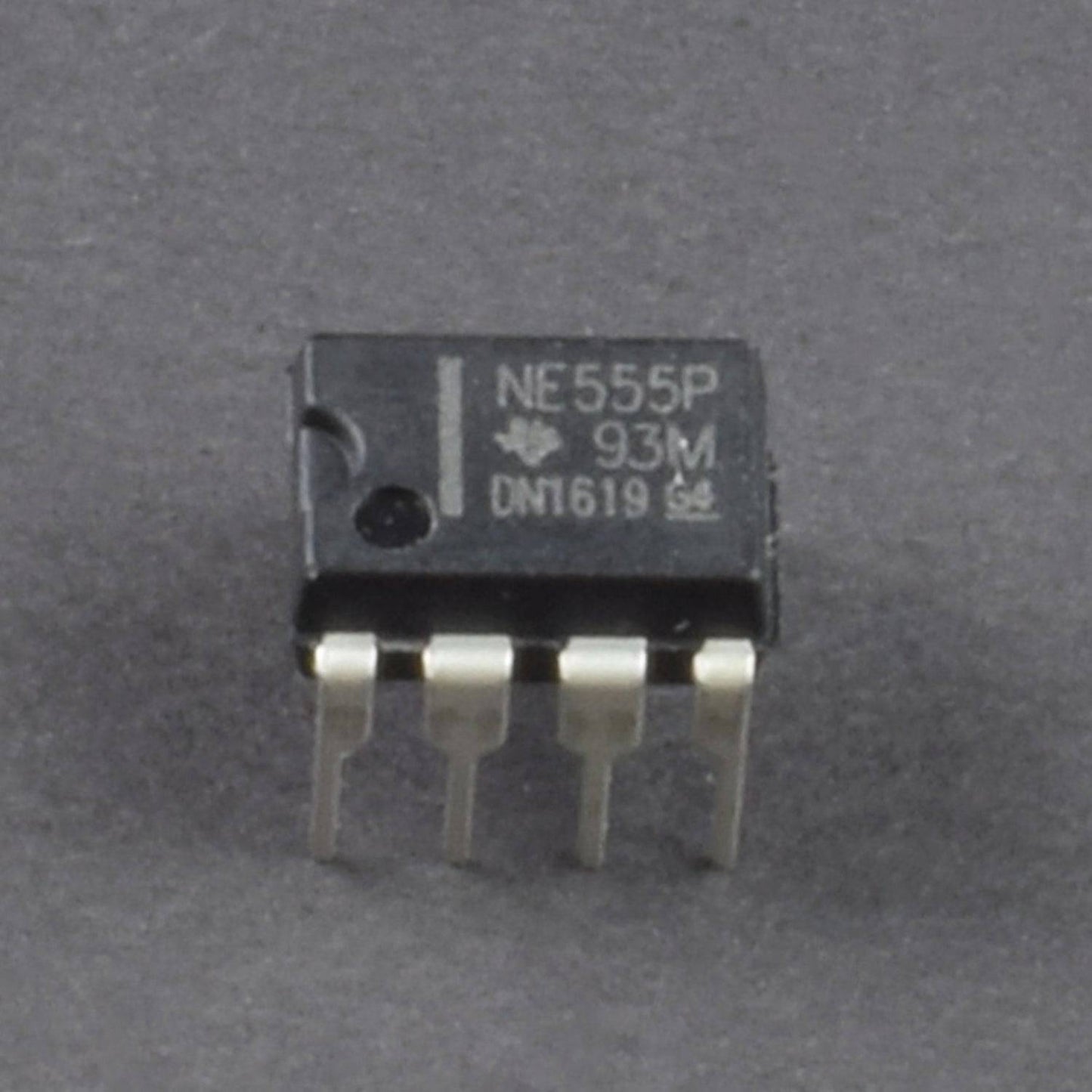
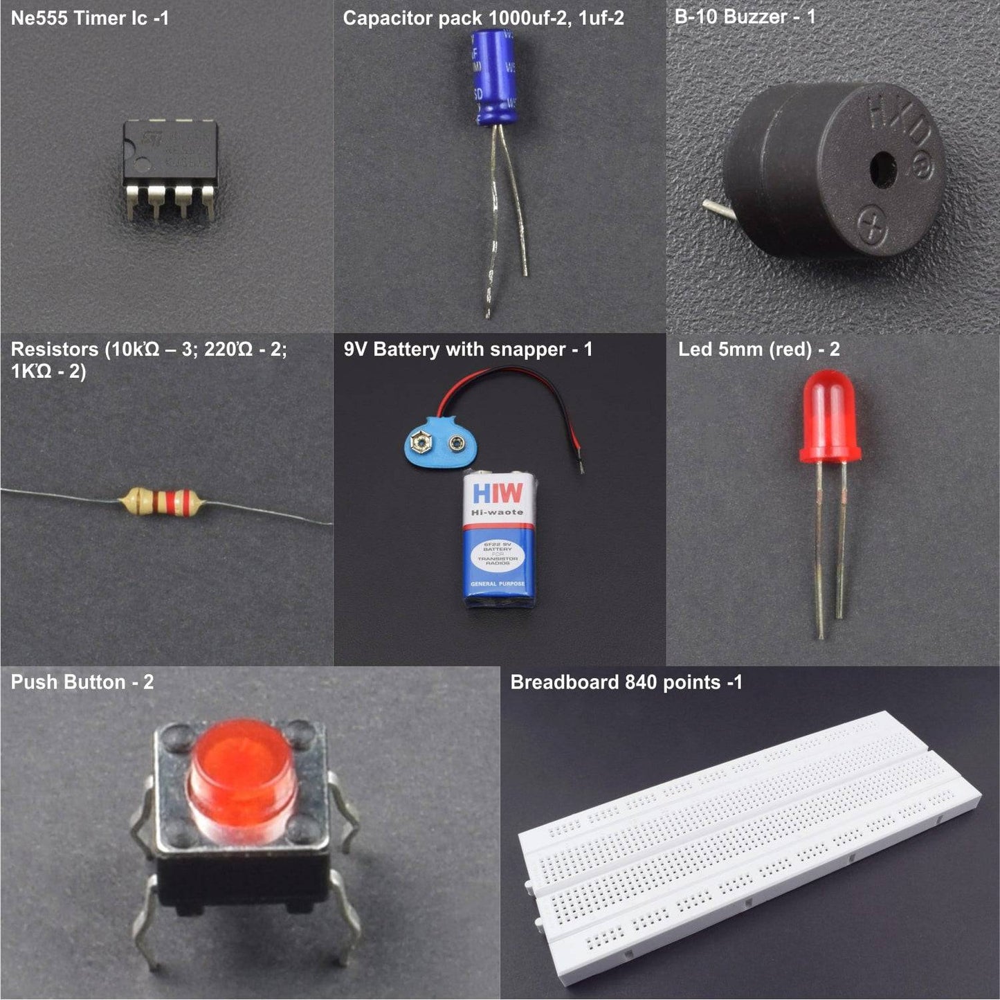
- 555 Timer IC - 2
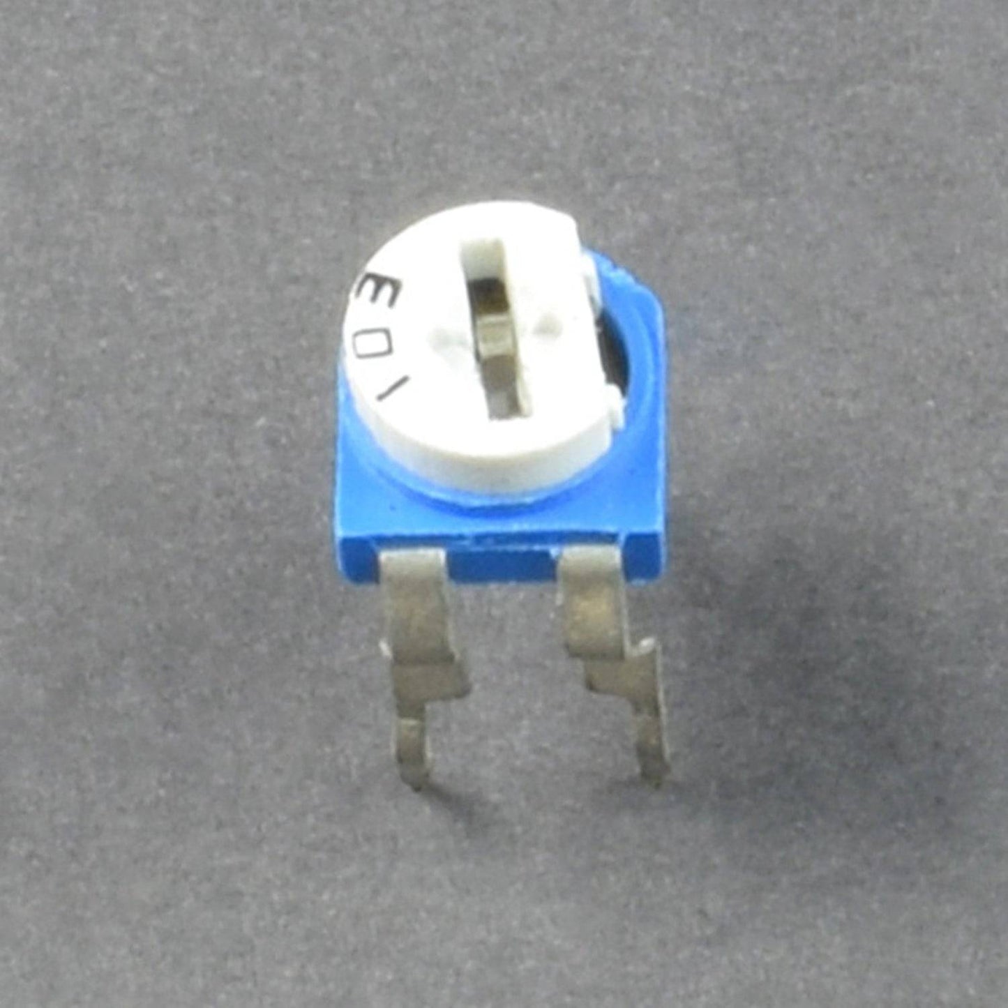
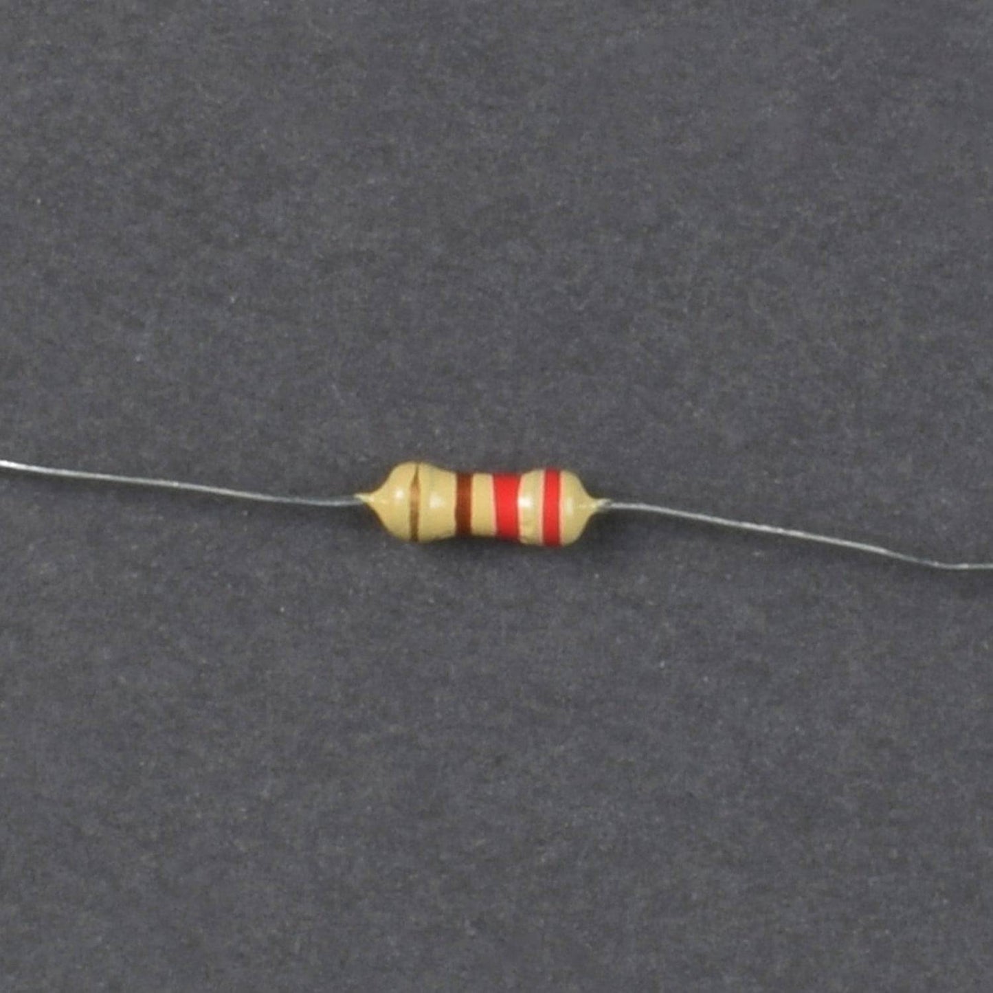
- Resistor pack (1K ohm-2, 10K ohm-2, 100K ohm-2)
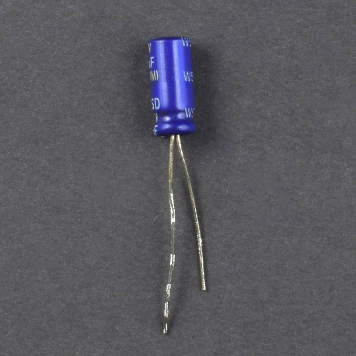
- Capacitor pack 1000uf-2, 1uf-2
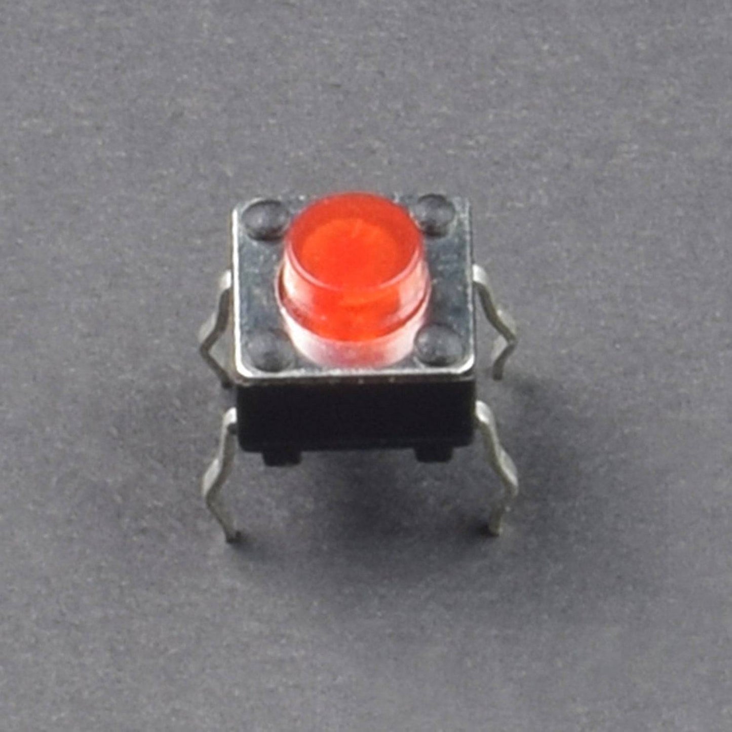
- Push button-2
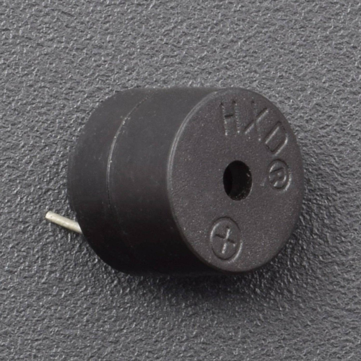
- Buzzer-1
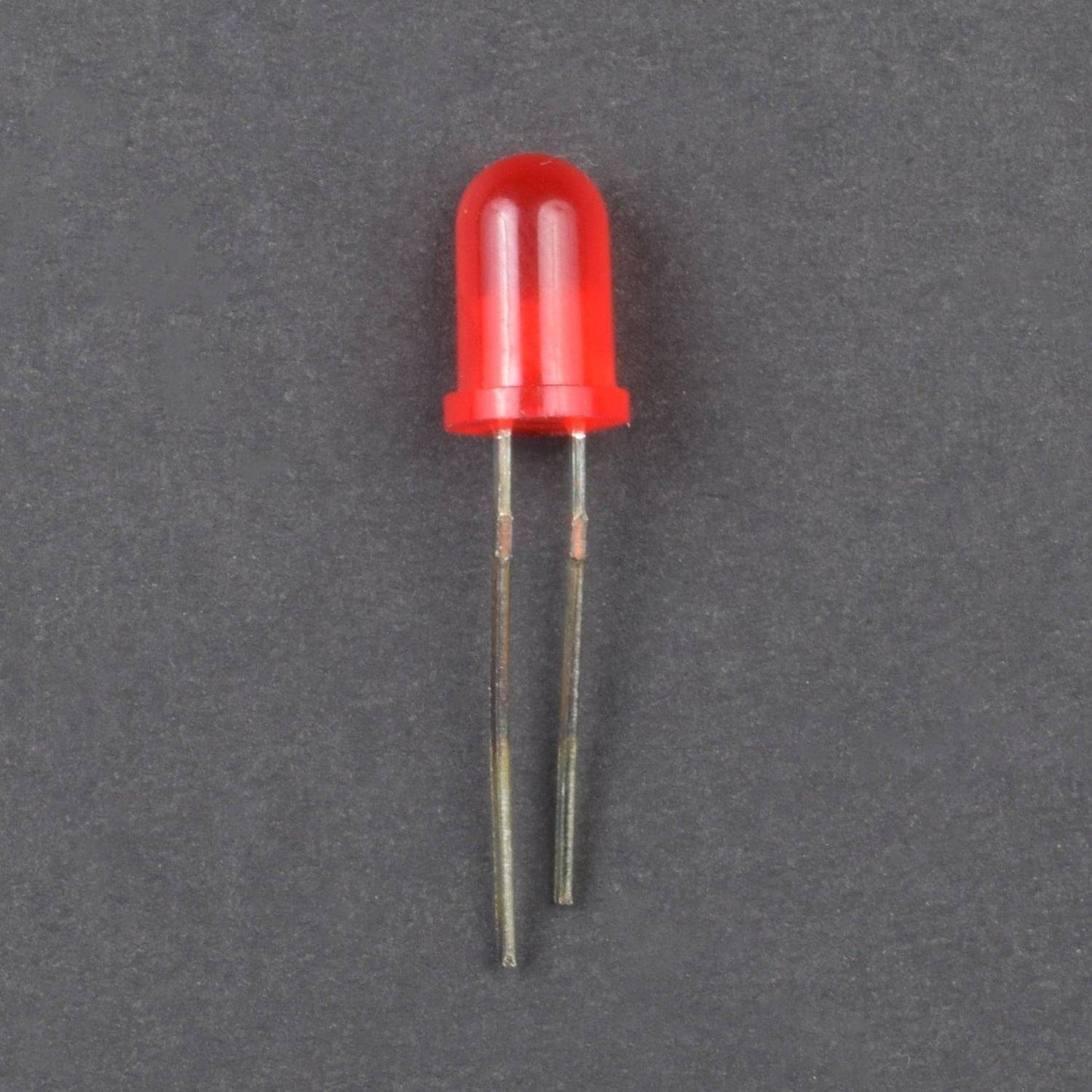
- Led 5mm (red) - 2
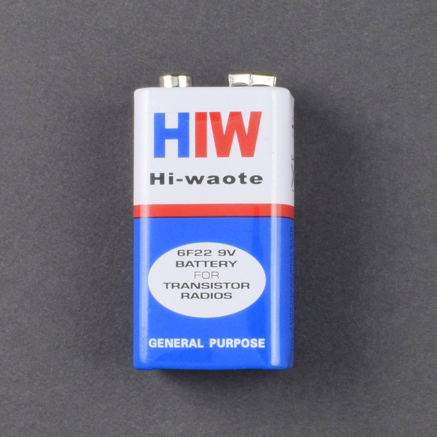
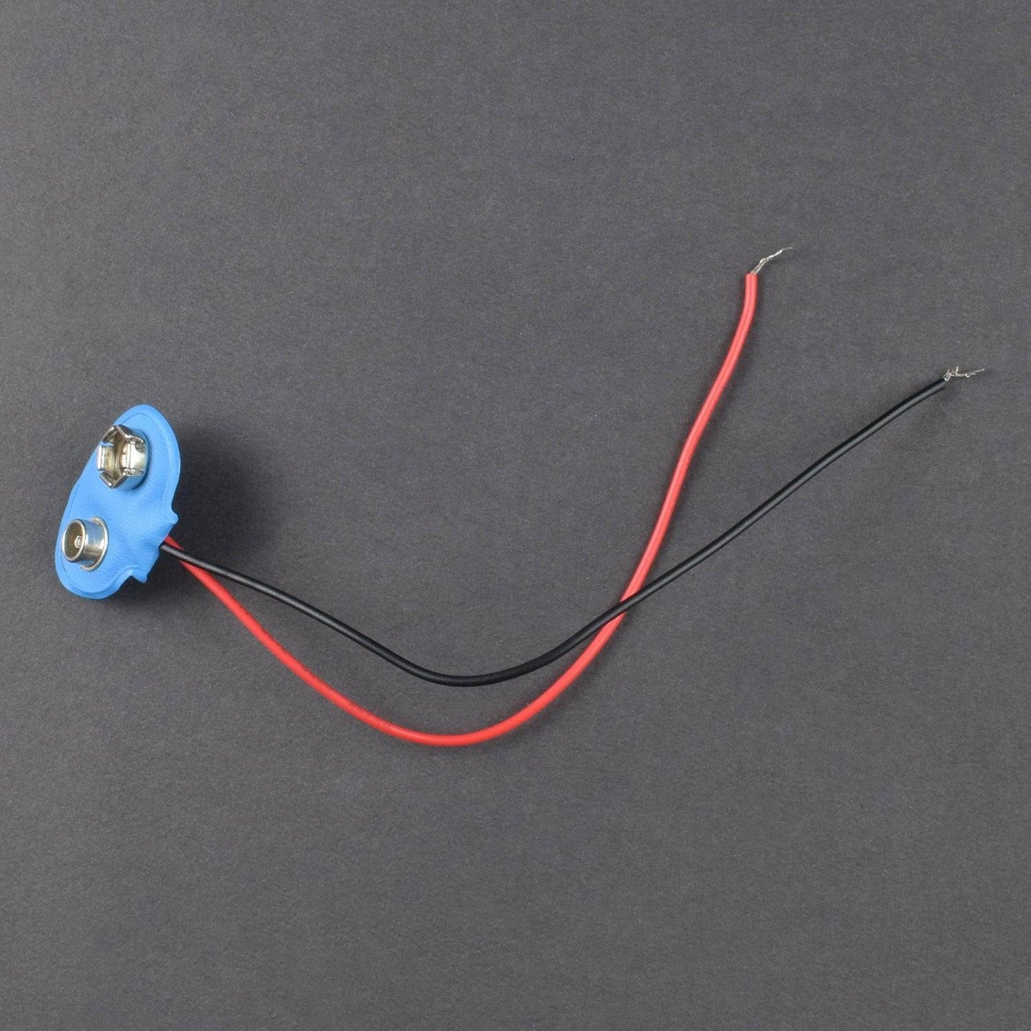
- Battery 9V -1
- Battery snapper - 1
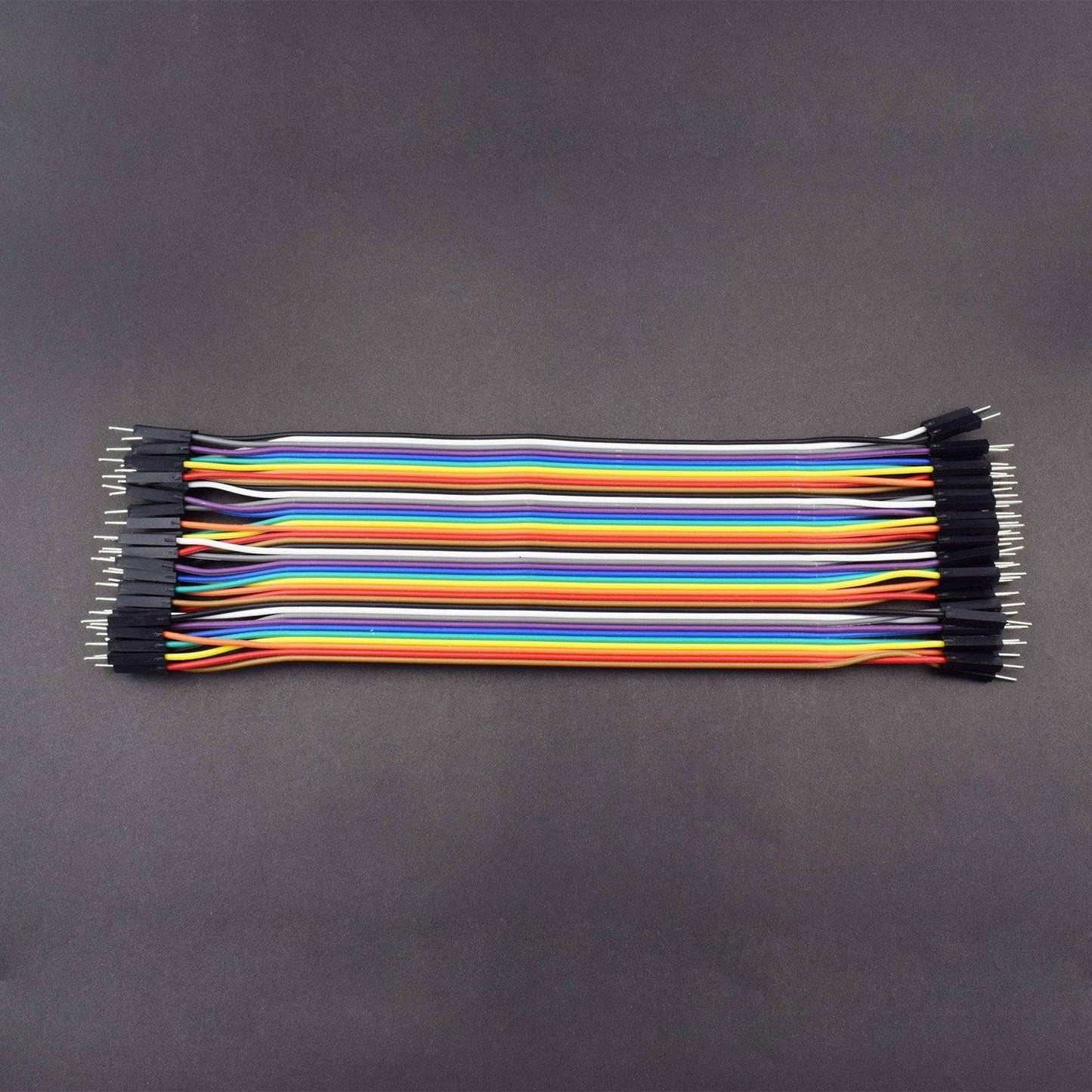
- Jumper wire (male to male) – 40 pieces
HARDWARE REQUIRED
- 555 Timer IC - 2
- Resistor pack (1K ohm-2, 10K ohm-2, 100K ohm-2)
- Capacitor pack 1000uf-2, 1uf-2
- Push button-2
- Buzzer-1
- Led 5mm (red) - 2
- Battery 9V -1
- Battery snapper - 1
- Jumper wire (male to male) – 40 pieces
SPECIFICATIONS
555 TIMER IC


Pin |
Name |
Purpose |
1 |
GND |
Ground reference voltage, low level (0 V) |
2 |
TRIG |
The OUT pin goes high and a timing interval starts when this input falls below 1/2 of CTRL voltage (which is typically 1/3 Vcc, CTRL being 2/3 Vcc by default if CTRL is left open). In other words, OUT is high as long as the trigger low. Output of the timer totally depends upon the amplitude of the external trigger voltage applied to this pin. |
3 |
OUT |
This output is driven to approximately 1.7 V below +Vcc, or to GND. |
4 |
RESET |
A timing interval may be reset by driving this input to GND, but the timing does not begin again until RESET rises above approximately 0.7 volts. Overrides TRIG which overrides threshold. |
5 |
CTRL |
Provides “control” access to the internal voltage divider (by default, 2/3 Vcc). |
6 |
THR |
The timing (OUT high) interval ends when the voltage at threshold is greater than that at CTRL (2/3 Vcc if CTRL is open). |
7 |
DIS |
Open collector output which may discharge a capacitor between intervals. In phase with output. |
8 |
Vcc |
Positive supply voltage, which is usually between 3 and 15 V depending on the variation. |

CAPACITOR

The Shorter Terminal is negative and the longer Terminal is Positive

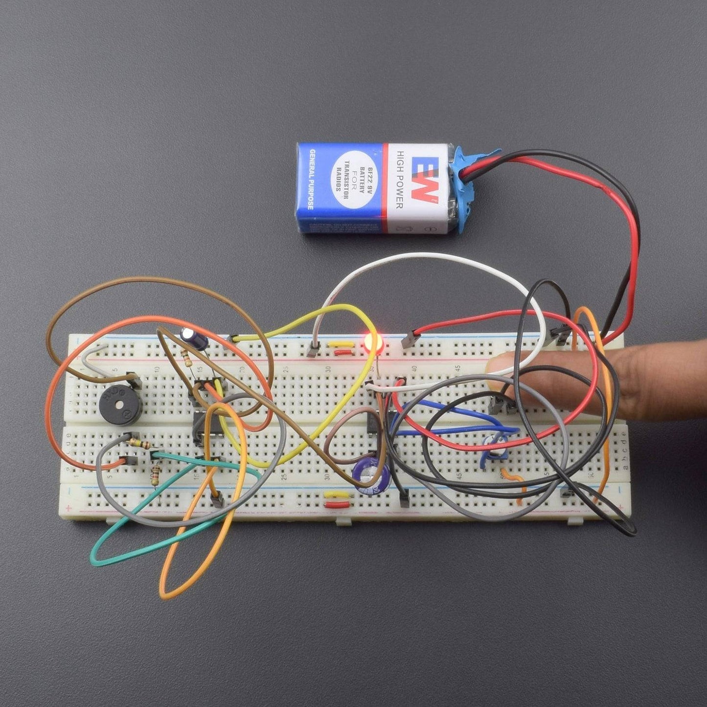
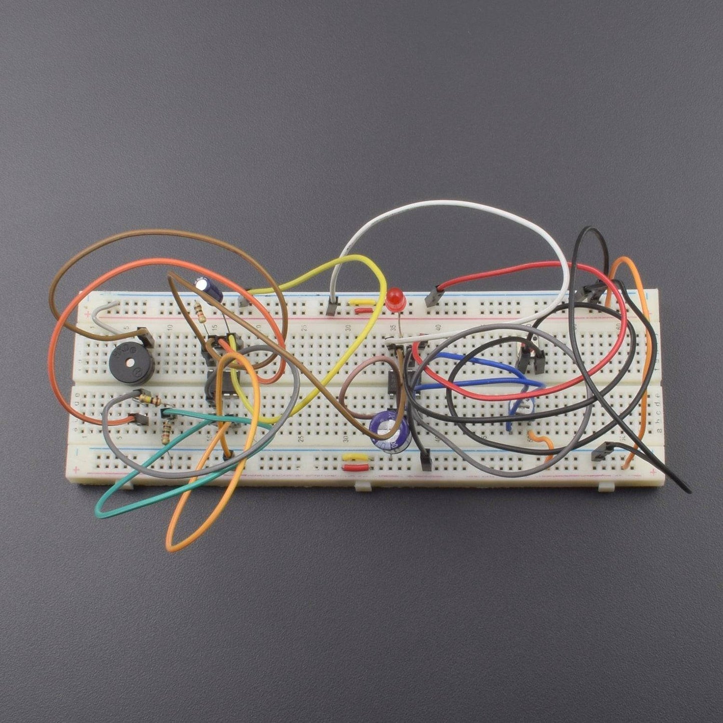
CIRCUIT DESCRIPTION
____

- Connect the 1st 555 timer IC and push button on the breadboard.
- 1st 555 timer IC pin no 1 connect to ground and pin no 8 is connected to the positive supply.
- Push button 1st leg is connected to the ground and 2nd leg is connected to the 1st 555 IC pin no 2.
- 1st 555 IC pin no 4 is connected to the positive supply.
- 1st 555 ic pin no 6 connected to the pin no 7 and pin no 6 to connected 1000uf capacitor’s positive leg and capacitor negative leg connects to ground
- Connect the 10k variable resistor on the breadboard and 10k variable resistor 1st leg(left) is connected to the positive supply and 2nd leg(right) is connected to the 1st 555 ic pin no 6 and 10k or 3rd leg(middle) is connected to the 1st 555 ic pin no 7
- 2nd 555 timer IC is connected to breadboard and pin no 1 connects to ground and pin no 8 is connected to the positive supply.
- 2nd 555 IC’s pin no 2 is connected to 1uf capacitor positive leg and capacitor negative leg connects to ground.
- 2nd 555 IC pin no 4 is connected to the 1st 555 IC pin no 3 and 2nd 555 IC pin no 4 is connected to resistor 10k ohm and resistor’s other leg is ground.
- 2nd 555 IC pin no 3 connected to buzzer positive leg and buzzer another leg to ground.
- 2nd 555 IC pin no 7 connected to 1k ohm resistor and resistor 2nd leg is connected to the positive supply.
- 2nd 555 ic pin no 7 connected to 100k ohm resistor and resistor 2nd leg is connected to the 2nd 555 ic pin no 6.
- 100k ohm resistor’s 2nd leg is connected to the 2nd 555 IC pin no 2.
- Breadboard connection: positive to positive and negative to negative.
- 1st 555 IC pin no 3 is connected to the led positive leg and led’s other leg connects to ground.
WORKING
we can control the time duration for which it keeps ringing upon pressing the push button. when press the push button then doorbell sound and led glow.