


REES52
Make a Digital Voltmeter Using 16*2 LCD Display Interfacing with Arduino Uno - KT931
Make a Digital Voltmeter Using 16*2 LCD Display Interfacing with Arduino Uno - KT931
SKU:KT931
100 in stock
Couldn't load pickup availability
- For Bulk Order Click Here
- Need Customer Support?
- Free Delivery Above 999/-
Note: In case you receive a damaged or faulty product, please return it in the original box with all foam and packaging. Returns will not be accepted if further damage occurs due to improper packing.
If you order a product that is currently in Preorder, and the price of that item increases in the future, you will be required to pay the difference in price.
For refund/return/replacement, call us at +91 95995 94520 or email us at support@rees52.com
Delivery Time
Delivery Time
- Delivery time with the Express Shipping option is 2-3 working days, and with the Standard Shipping option is 5-6 working days. It varies based on location, reliant on courier services.
- Delivery time if the order item is on Preorder Status is 15-20 working days.
COD (Cash on Delivery)
COD (Cash on Delivery)
- For COD you have to pay extra charges of Rs 350/- before the shipment. (We will share the company QR Code, UPI ID or Account details for the same)
INRODUCTION
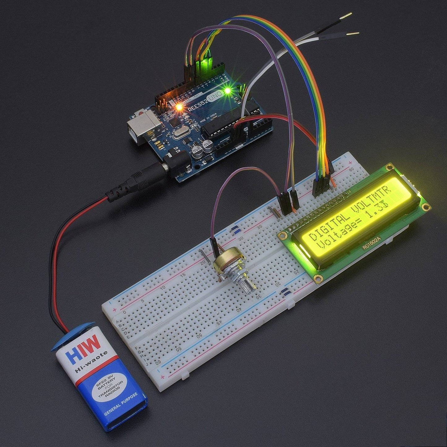
In this tutorial, we are making a Digital Voltmeter using a 16*2 LCD Display with Arduino Uno. It's relatively simple to use an Arduino to measure voltages. The Arduino has several analog input pins that connect to an analog-to-digital converter (ADC) inside the Arduino. The Arduino ADC is a ten-bit converter, meaning the output value will range from 0 to 1023. We will obtain this value by using the analogRead() function. This project will show you the values up to 5v.
If you know the reference voltage--in this case, we will use 5 V--you can easily calculate the voltage present at the analog input. To display the measured voltage, we will use a liquid crystal display (LCD) that has two lines of 16 characters.
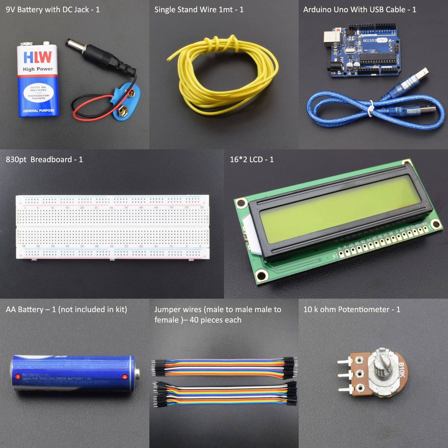
HARDWARE REQUIRED
- Arduino Uno - 1pc
- USB Cable - 1pc
- 16*2 LCD - 1pc
- 10 k Ohm Potentiometer - 1pc
- Breadboard 830 Points - 1pc
- Jumper Wires Male to Male – 40 pieces
- Jumper Wires Male to Female – 40 pieces
- 9v Battery -1pc
- Snapper with DC Jack – 1pc
- AA Battery - 1pc not included in the package
- Single Stand Wire - 2 mtr
SOFTWARE REQUIRED
Arduino IDE 1.8.10 (programmable platform for Arduino)
Click here to download the software

SPECIFICATIONS
16*2 LCD Display:
- LCD Display Mode: STN, Positive, Transflective
- Display Colour: Deep Blue/ Yellow Green
- Viewing Angle: 6h
- Driving Method: 1/16 duty, 1/5 bias
- Back Light: Yellow-Green LED backlight
- Outline Dimension: 803615.8 MAX

CAUTIONS
- The LCD panel is made of glass. Any mechanical shock (e.g. dropping from a high place) will damage the LCD module.
- Do not add excessive force to the surface of the display, which may cause the Display colour to change abnormally.
- The polariser on the LCD is easily scratched. If possible, do not remove the LCD protective film until the last step of installation.
- Never attempt to disassemble or rework the LCD module.
- Only Clean the LCD with Isopropyl Alcohol or Ethyl Alcohol. Other solvents (eg, water) may damage the LCD.
- When mounting the LCD module, make sure that it is free from twisting, warping and distortion.
- Ensure to provide enough space (with cushion) between the case and LCD panel to prevent external force from adding to it, or it may cause damage to the LCD or degrade the display result.
- Only hold the LCD module by its side. Never hold the LCD module by adding force to the heat seal of the TAB.
- Never add force to the component of the LCD module. It may cause invisible damage or a degradation of the reliability.
- The LCD module could be easily damaged by static electricity. Be careful to maintain an optimum anti-static work environment to protect the LCD module.
- When peeling off the protective film from the LCD, static charge may cause an abnormal display pattern. It is normal and will resume to normal in a short while.
- Take care and prevent getting hurt by the LCD panel's sharp edge.
- Never operate the LCD module exceed the absolute maximum ratings.
- Keep the signal line as short as possible to prevent a noisy signal from being applied to the LCD module.
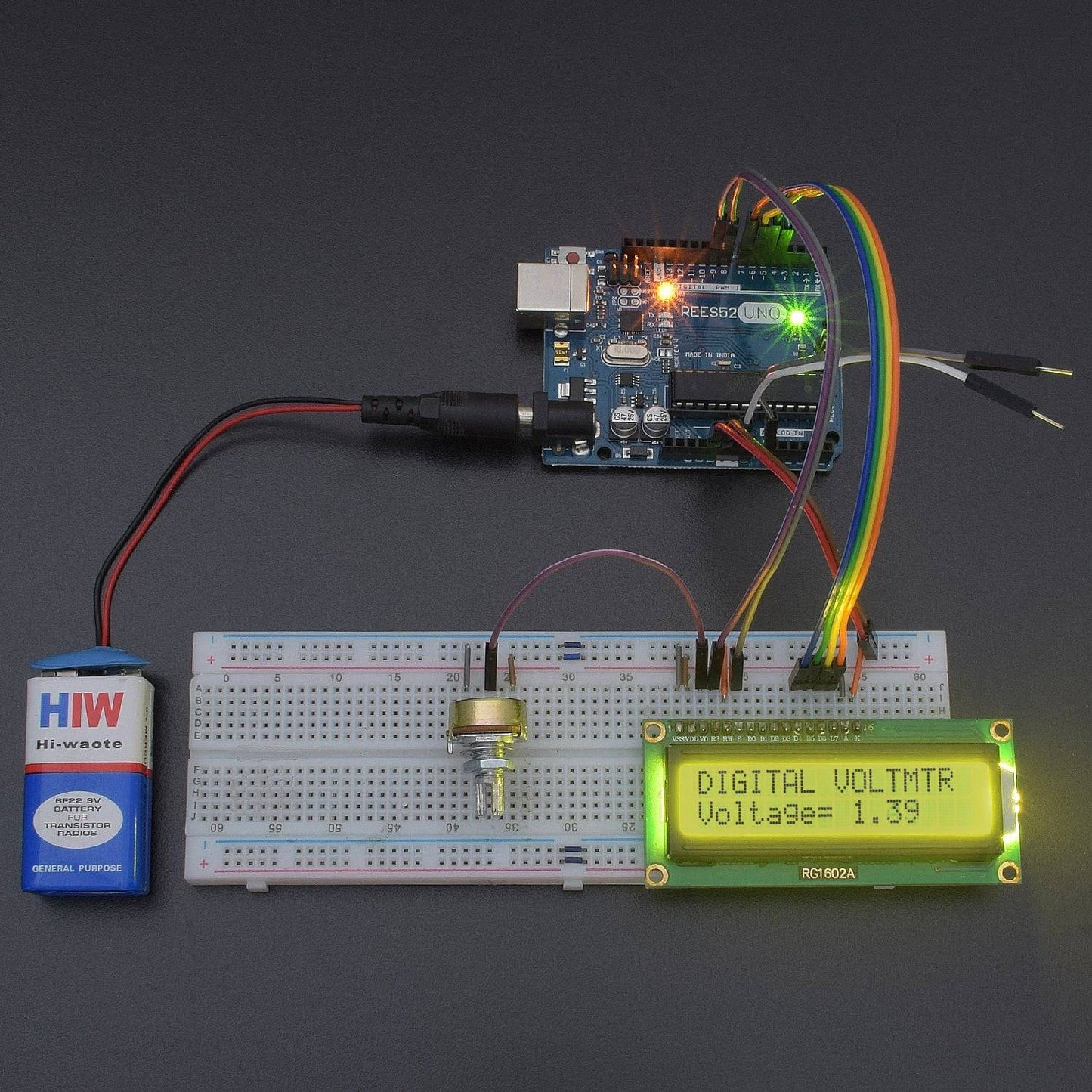
CIRCUIT CONNECTION
The 16x2 LCD used in this experiment has a total of 16 pins. As shown in the table below, eight of the pins are data lines (pins 7-14), two are for power and ground (pins 1 and 16), three are used to control the operation of LCD (pins 4-6), and one is used to adjust the LCD screen brightness (pin 3). The remaining two pins (15 and 16) power the backlight.

Note that the potentiometer is connected to the 5v source and GND, and the middle terminal is connected to pin 3 of the LCD. Rotating this pot changes the brightness of the LCD. The four data pins DB4-DB7 are connected to the Arduino pins 4-7. Enable is connected to pin 9 of the Arduino, and RS is connected to pin 8 of the Arduino. RW is connected to ground. The backlight LED is connected to 5v and ground. The following table shows the pin connections:
DB4 ----->pin4
DB5 ----->pin5
DB6 ----->pin6
DB7 ----->pin7
RS ----->pin8
EN ----->pin9
CODE
The program below uses the Liquid Crystal library. This library contains all of the functions needed to write to the LCD.
The loop reads the analogue value from the analogue input, and because the reference voltage is 5 V, it multiples that value by 5, then divides by 1024 to calculate the actual voltage value. Once the voltage has been calculated, the value is written to the LCD.
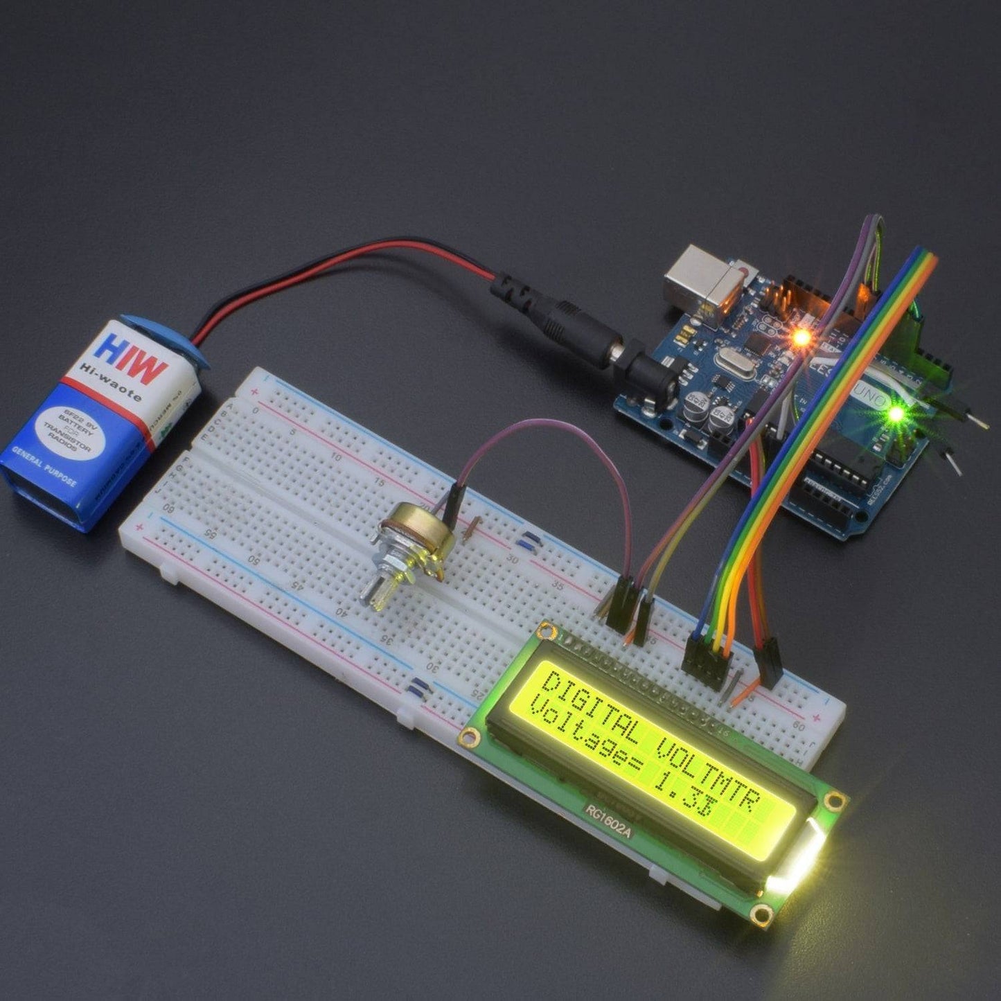
WORKING
In this project, we will show the voltage of the battery on a 16*2 LCD Display and Serial Monitor, also using the Digital Voltmeter project. You can verify the values using a multimeter available in markets.
Connect the A0 wire to the positive pin of the battery and the Gnd Wire to the negative pin of the battery. The Output will show on the LCD.
This project will show you the values up to 5v.
To measure voltages greater than the 5 V reference voltage, you need to divide the input voltage so that the voltage actually input to the Arduino is 5 V or less. in this experiment, we will use a 90.9k ohm resistor and a 10k ohm resistor to create a 10:1 divider. This will allow us to measure voltages up to 50 V.