

vendor-unknown
MAKE A DATA LOGGER USING DS3231 RTC MODULE INTERFACING WITH ARDUINO NANO - KT876
MAKE A DATA LOGGER USING DS3231 RTC MODULE INTERFACING WITH ARDUINO NANO - KT876
SKU:KT876
999 in stock
Couldn't load pickup availability
- For Bulk Order Click Here
- Need Customer Support?
- Free Delivery Above 999/-
Note: In case you receive a damaged or faulty product, please return it in the original box with all foam and packaging. Returns will not be accepted if further damage occurs due to improper packing.
If you order a product that is currently in Preorder, and the price of that item increases in the future, you will be required to pay the difference in price.
For refund/return/replacement, call us at +91 95995 94520 or email us at support@rees52.com
Delivery Time
Delivery Time
- Delivery time with the Express Shipping option is 2-3 working days, and with the Standard Shipping option is 5-6 working days. It varies based on location, reliant on courier services.
- Delivery time if the order item is on Preorder Status is 15-20 working days.
COD (Cash on Delivery)
COD (Cash on Delivery)
- For COD you have to pay extra charges of Rs 350/- before the shipment. (We will share the company QR Code, UPI ID or Account details for the same)
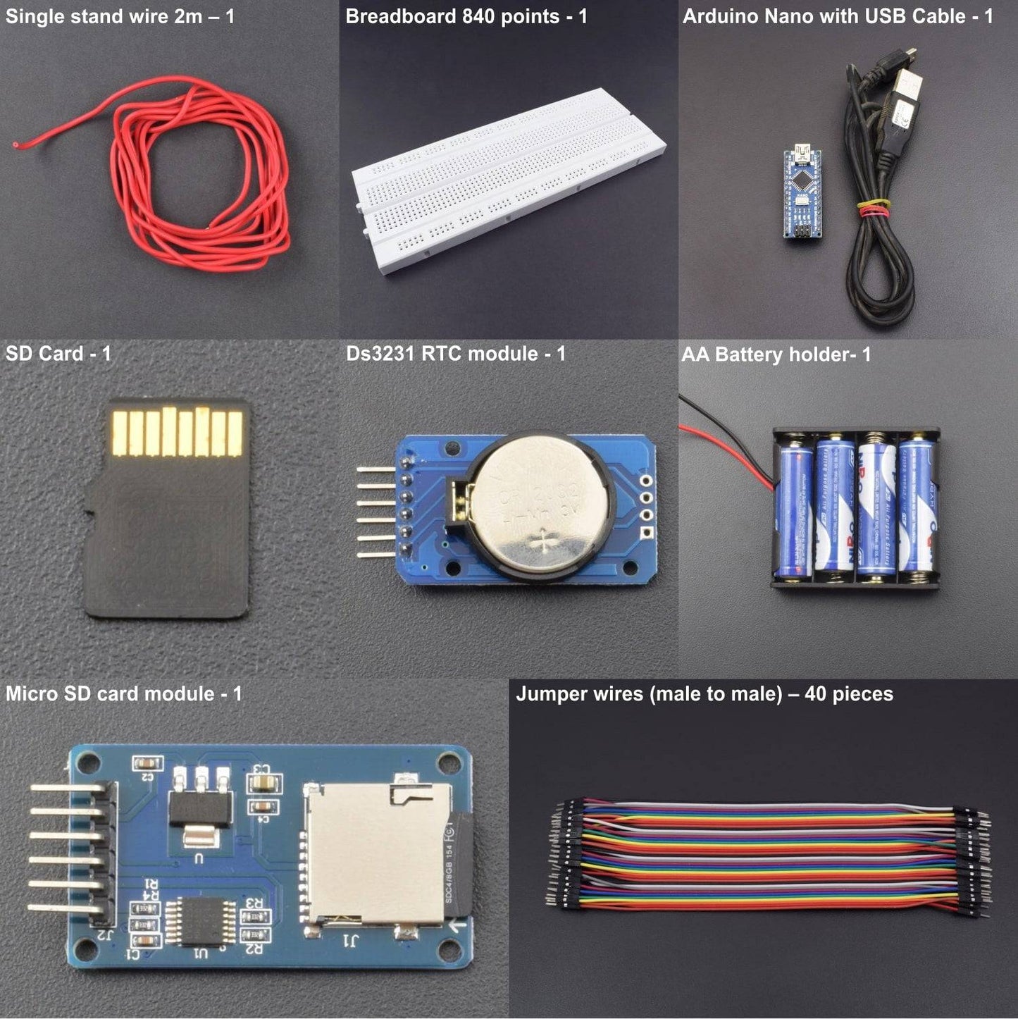


KIT INCLUDES:
- DS3231 RTC module - 1
- Micro SD card module - 1
- Arduino Nano with USB Cable - 1
- AA Battery holder- 1
- Breadboard 840 points - 1
- Jumper wires (male to male) – 40 pieces
- AA Batteries-4 (not included in the package)
- Single stand wire 2m – 1
- 4gb SD card – 1(not included in the package)
HARDWARE REQUIRED
- DS3231 RTC module - 1
- Micro SD card module - 1
- Arduino Nano with USB Cable - 1
- AA Battery holder- 1
- Breadboard 840 points - 1
- Jumper wires (male to male) – 40 pieces
- AA Batteries-4 (not included in the package)
- Single stand wire 2m – 1
- 4gb SD card – 1(not included in the package)
SOFTWARE REQUIRED
Arduino IDE 1.8.5 (programmable platform for Arduino)
Click To Download :https://www.arduino.cc/en/Main/Software

SPECIFICATIONS
DS3231 RTC MODULE
|
Operating Voltage |
3.3 V-5.5 V DC |
|
Chip |
DS3231 |
|
Pin no. |
6 |
|
Operating Temperature Ranges |
Commercial: 0°C to +70°C |
|
Industrial: -40°C to +85°C |
|
|
Power Consumption |
Low |
|
Accuracy ±2ppm |
0°C to +40°C |
|
Accuracy ±3.5ppm |
-40°C to +85°C |
|
I2C Interface |
Fast (400KHZ) |
|
Digital Temp Sensor Output |
±3°C Accuracy |
SD CARD MODULE
- Operating voltage 5V
- SPI Communication method
- SD card Socket
- Supports FAT16 and FAT32
- Support 2gb to 4gb
ARDUINO NANO
- Microcontroller: Atmel ATmega168 or ATmega328
- Operating Voltage(logic level): 5 V
- Input Voltage(recommended): 7-12 V
- Input Voltage(limits): 6-20 V
- Digital I/O Pins: 14 (of which 6 provide PWM output)
- Analog Input Pins: 8
- DC Current per I/O Pin: 40 mA
- Flash Memory: 16 KB (ATmega168) or 32 KB (ATmega328) of which 2 KB used by bootloader
- SRAM: 1 KB (ATmega168) or 2 KB (ATmega328)
- EEPROM: 512 bytes (ATmega168) or 1 KB (ATmega328)
- Clock Speed: 16 MHz
PIN DESCRIPTION
DS3231 RTC MODULE
.jpg)
|
PIN |
NAME |
FUNCTION |
|
1 |
32KHZ |
32kHz Output. This open-drain pin requires an external pullup resistor. It may be left open if not used. |
|
2 |
VCC |
DC Power Pin for Primary Power Supply. This pin should be decoupled using a 0.1µF to 1.0µF capacitor. If not used, connect to ground. |
|
3 |
INT/SQW |
Active-Low Interrupt or Square-Wave Output. This open-drain pin requires an external pullup resistor. It may be left open if not used. This multifunction pin is determined by the state of the INTCN bit in the Control Register (0Eh). When INTCN is set to logic 0, this pin outputs a square wave and its frequency is determined by RS2 and RS1 bits. When INTCN is set to logic 1, then a match between the timekeeping registers and either of the alarm registers activates the INT/SQW pin (if the alarm is enabled). Because the INTCN bit is set to logic 1 when power is first applied, the pin defaults to an interrupt output with alarms disabled. |
|
4 |
GND |
ground |
|
5 |
SDA |
Serial Data Input/Output. This pin is the data input/output for the I2C serial interface. This open-drain pin requires an external pullup resistor. |
|
6 |
SCL |
Serial Clock Input. This pin is the clock input for the I2C serial interface and is used to synchronize data movement on the serial interface.
|
ARDUINO NANO

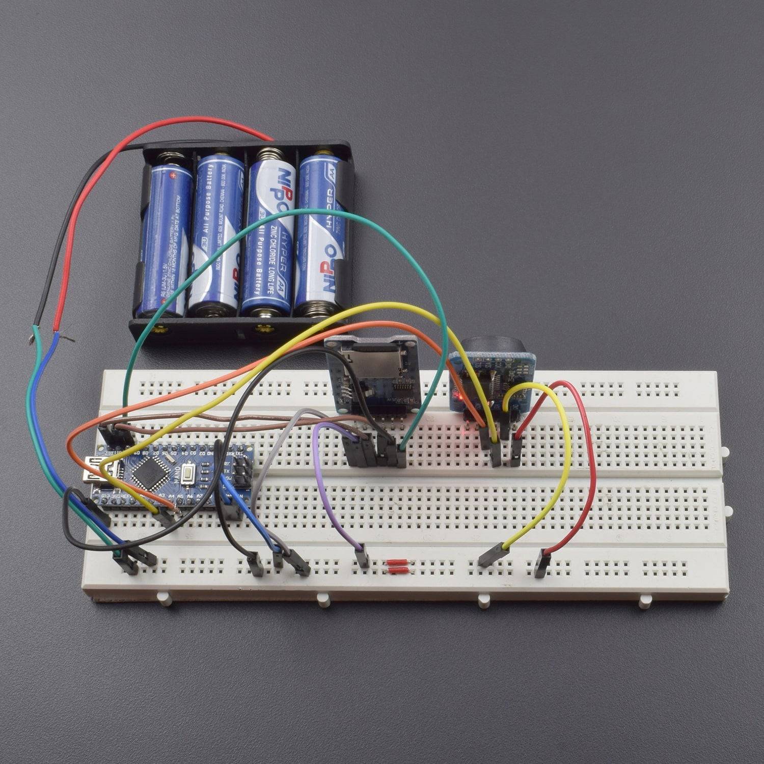
CIRCUIT CONNECTION

- Connect all the vcc from the battery holder to the breadboard positive and all the grounds to the negative.
- Connect the SCL pin of ds3231 to arduino Nano a5 pin, and SDA to a4.
- Connect cs pin of SD card module to D10 of arduino Nano SCK to D13,MOSI to D11,MISO to D12.
- Now connect the battery positive to + lane on breadboard and negative to negative lane of breadboard.
CODE
Click to see the code or copy the link:
WORKING
In this project we are going to use arduino Nano, SD card module, and DS3231 real time module. This project reads temperature in every few minutes and save the data in the SD card. The DS3231 has a temperature sensor embedded in it in with the help of arduino Nano the ds3231 RTC will record the real time and temperature and save it in the SD card which is placed in the SD card module.