


vendor-unknown
Make a calculator with the help of 4*4 keypad membrane interfacing with Arduino uno - KT810
Make a calculator with the help of 4*4 keypad membrane interfacing with Arduino uno - KT810
SKU:KT810
1000 in stock
Couldn't load pickup availability
- For Bulk Order Click Here
- Need Customer Support?
- Free Delivery Above 999/-
Note: In case you receive a damaged or faulty product, please return it in the original box with all foam and packaging. Returns will not be accepted if further damage occurs due to improper packing.
If you order a product that is currently in Preorder, and the price of that item increases in the future, you will be required to pay the difference in price.
For refund/return/replacement, call us at +91 95995 94520 or email us at support@rees52.com
Delivery Time
Delivery Time
- Delivery time with the Express Shipping option is 2-3 working days, and with the Standard Shipping option is 5-6 working days. It varies based on location, reliant on courier services.
- Delivery time if the order item is on Preorder Status is 15-20 working days.
COD (Cash on Delivery)
COD (Cash on Delivery)
- For COD you have to pay extra charges of Rs 350/- before the shipment. (We will share the company QR Code, UPI ID or Account details for the same)

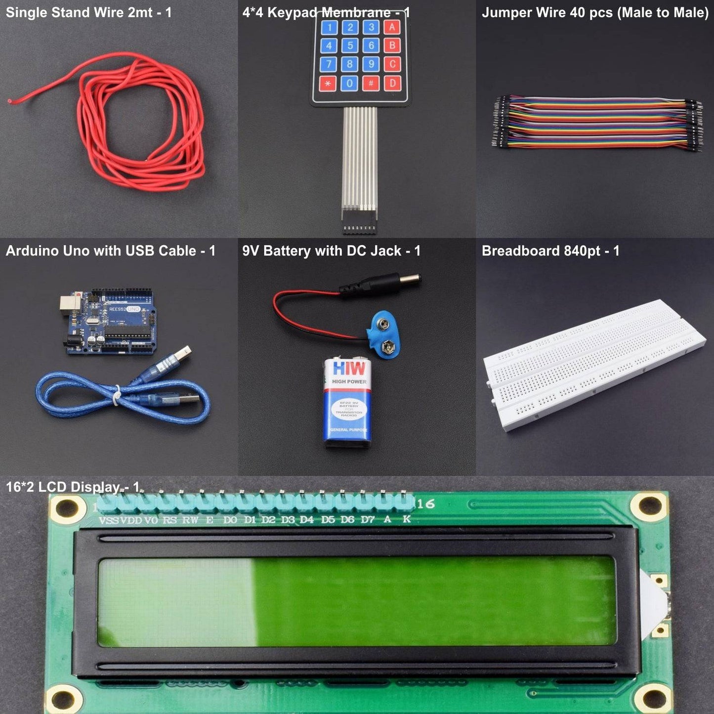

KIT INCLUDES:
- 4x4 keypad membrane -1
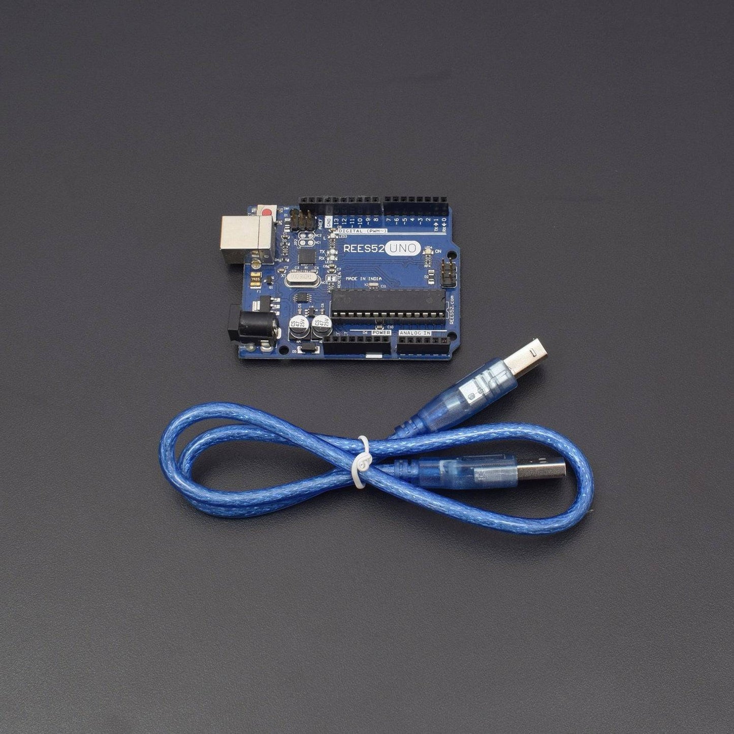
- Arduino uno with USB cable - 1
- 16x2 LCD display -1
- Jumper wires ( male to male) – 40 pieces
- 9V battery with DC Jack - 1
- Breadboard 840 points - 1
- Single stand wire 2mt- 1
HARDWARE REQUIRED
- 4x4 keypad membrane -1
- Arduino uno with USB cable - 1
- 16x2 LCD display -1
- Jumper wires ( male to male) – 40 pieces
- 9V battery with DC Jack - 1
- Breadboard 840 points - 1
- Single stand wire 2mt- 1
SOFTWARE REQUIRED
Arduino IDE 1.8.5 (programmable platform for Arduino)
Click To Download :https://www.arduino.cc/en/Main/Software

SPECIFICATIONS
4*4 KEYPAD MEMBRANE
- Maximum Rating: 24 VDC, 30 mA
- Interface: 8-pin access to 4x4 matrix
- Operating temperature: 32 to 122 °F(0 to 50°C)
- Dimensions: Keypad, 2.7 x 3.0 in (6.9 x 7.6 cm),Cable: 0.78 x 3.5 in (2.0 x 8.8 cm)
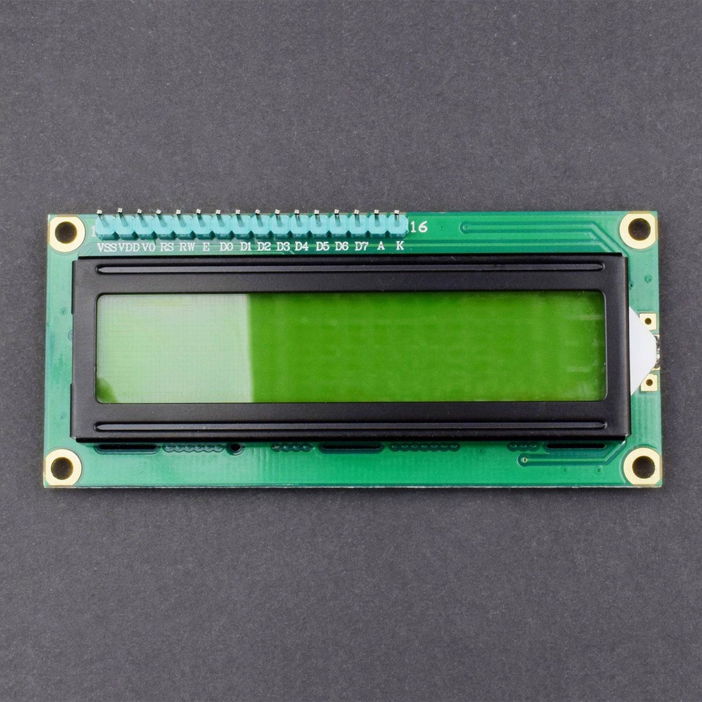
16*2 LCD DISPLAY
- LCD Display Mode: STN, Positive, Transflective
- Display Colour: Deep Blue/ Yellow Green
- Viewing Angle: 6H
- Driving Method: 1/16 duty, 1/5 bias
- Back Light: Yellow-Green LED backlight
- Outline Dimension: 803615.8 MAX
Note |
|
PIN DESCRIPTION
16*2 LCD DISPLAY
Symbol |
External Connection |
Function |
VSS |
Power Supply |
Signal GROUND for lcm |
VDD |
POWER SUPPLY for logic lcm |
|
V0 |
Contrast Adjust |
|
RS |
MPU |
Register Select Signal |
RW |
MPU |
Read/Write Select Signal |
E |
MPU |
Operation Enable Signal |
DB0~DB3 |
MPU |
Four Low order bidirectional three state bus lines. Used for data transfer between the MPU and LCM. These four are not used between 4 Bit operations. |
DB4~DB7 |
MPU |
Four high order bidirectional Three state bus lines used for data transfer between the MPU |
A |
LED BKL power Supply |
Power Supply for BKL |
K |
4*4 KEYPAD MEMBRANE

Matrix keypads use a combination of four rows and four columns to provide button states to the host device, typically a microcontroller. Underneath each key is a pushbutton, with one end connected to one row, and the other end connected to one column.
CIRCUIT CONNECTION
- Keypad 1 to arduino D0
- Keypad 2 to D1
- Keypad 3 to D2
- Keypad 4 to D3
- Keypad 5 to D4
- Keypad 6 to D5
- Keypad 7 to D6
- Keypad 8 to D7
- Lcd pic 16 to negative rail and pin 15 to positive rail
- Lcd pic D7 to D4 to arduino D13 to D10
- Arduino 5V to positive rail and ground to negative rail
- Arduino pin D8 to RS of lcd and D9 to pin 6 (E) of lcd
- Lcd pin1 to ground, pin 2 to 5v , pin 3 to ground and pin 5 to ground

CODE
Programming is always fun and Arduino is a wonderful platform if you are just getting started with Embedded programming. In this, we will build our own calculator with Arduino. The values can be sent in through a keypad (4×4 keypad) and the result can be viewed on an LCD screen (16×2 Dot-matrix). This calculator could perform simple operations like Addition, Subtraction, Multiplication and Division with whole numbers.
The complete circuit diagram of this Arduino Calculator Project is given above. The +5V and ground connection shown in the circuit diagram can be obtained from the 5V and ground pin of the Arduino. The Arduino itself can be powered from your laptop or through the DC jack using a 12V adapter or 9V battery.
We are operating the LCD in 4-bit mode with Arduino so only the last four data bits of the LCD is connected to Arduino. The Keyboard will have 8 output pins which have to be connected from pin 0 to pin 7 as shown above. You can use the following connection to verify your connection with Arduino, you can also check 4x4 Keypad interfacing with Arduino.
"Some Arduino boards might show an error while uploading program if there is anything connected to pin 0 and pin1, so if you experience any just remove the keypad while uploading the program.
As told earlier we are going to interface an LCD and keypad with Arduino using libraries. So let’s add them to our Arduino IDE first. The library for LCD is already included in your Arduino by default so we need not worry about it. For Keypad library click on the link to download it from Github. You will get a ZIP file, then add this lib to Arduino by Sketch -> Include Library -> Add.ZIP file and point the location to this downloaded file. Once done we are all set for programming.
Even though we have used a library for using a keypad we have to mention few details (shown below) about the keypad to the Arduino. The variable ROWS and COLS will tell how many rows and columns our keypad has and the key map shows the order in which the keys are present on the keyboard
WORKING
- Make the connections as per circuit diagram and upload the code below. If it shows error make sure you have added the library as per the instruction is given below
Library Links:
https://www.arduino.cc/en/Reference/LiquidCrystal
https://github.com/Chris--A/Keypad
- Arduino Calculator using 4x4 Keypad in action
- Since the keypad used here does not have proper markings on it I have assumed the Alphabets to be operators as listed below.
Character on Keypad assumed to be
“D” Addition (+)
“A" Subtraction (-)
“B” Multiplication (*)
“C” Division (/)
“*” Clear (C)
“#” Equals (=)