
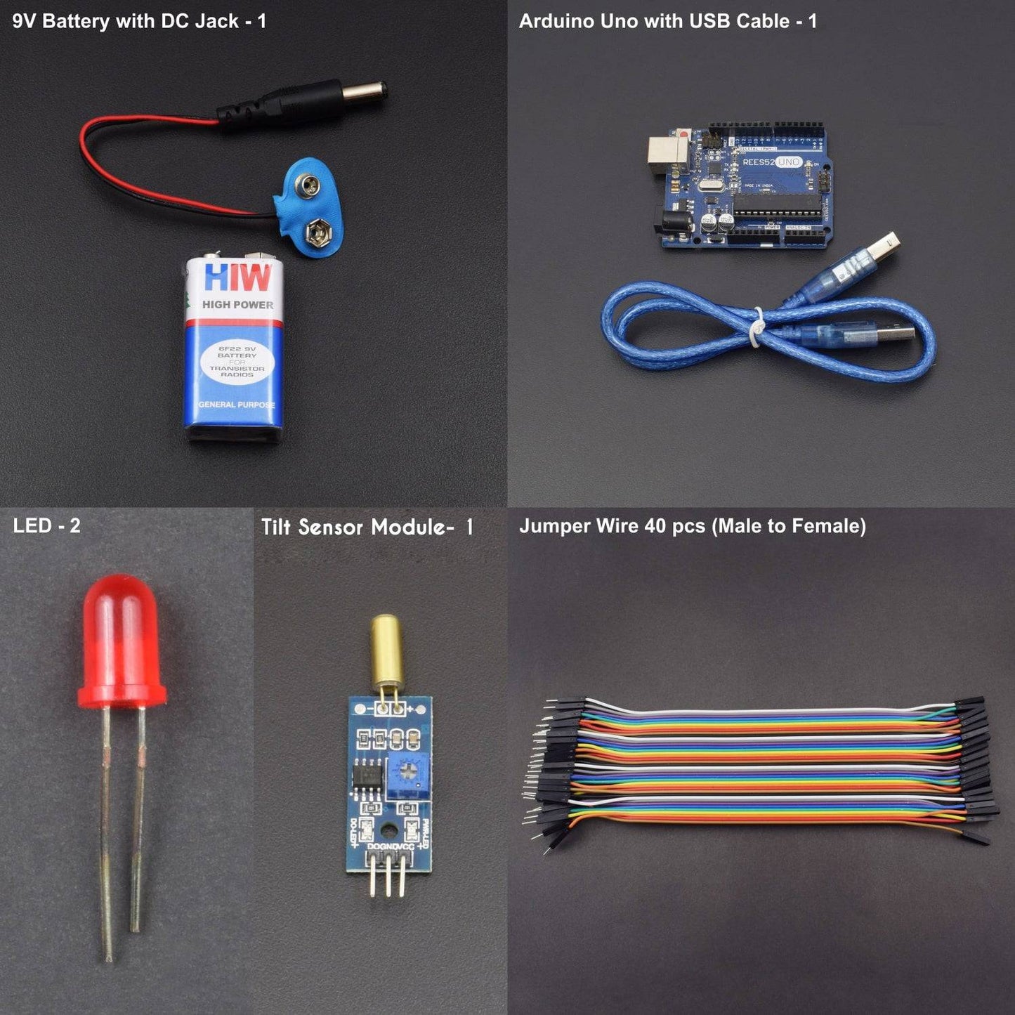
KIT INCLUDED:
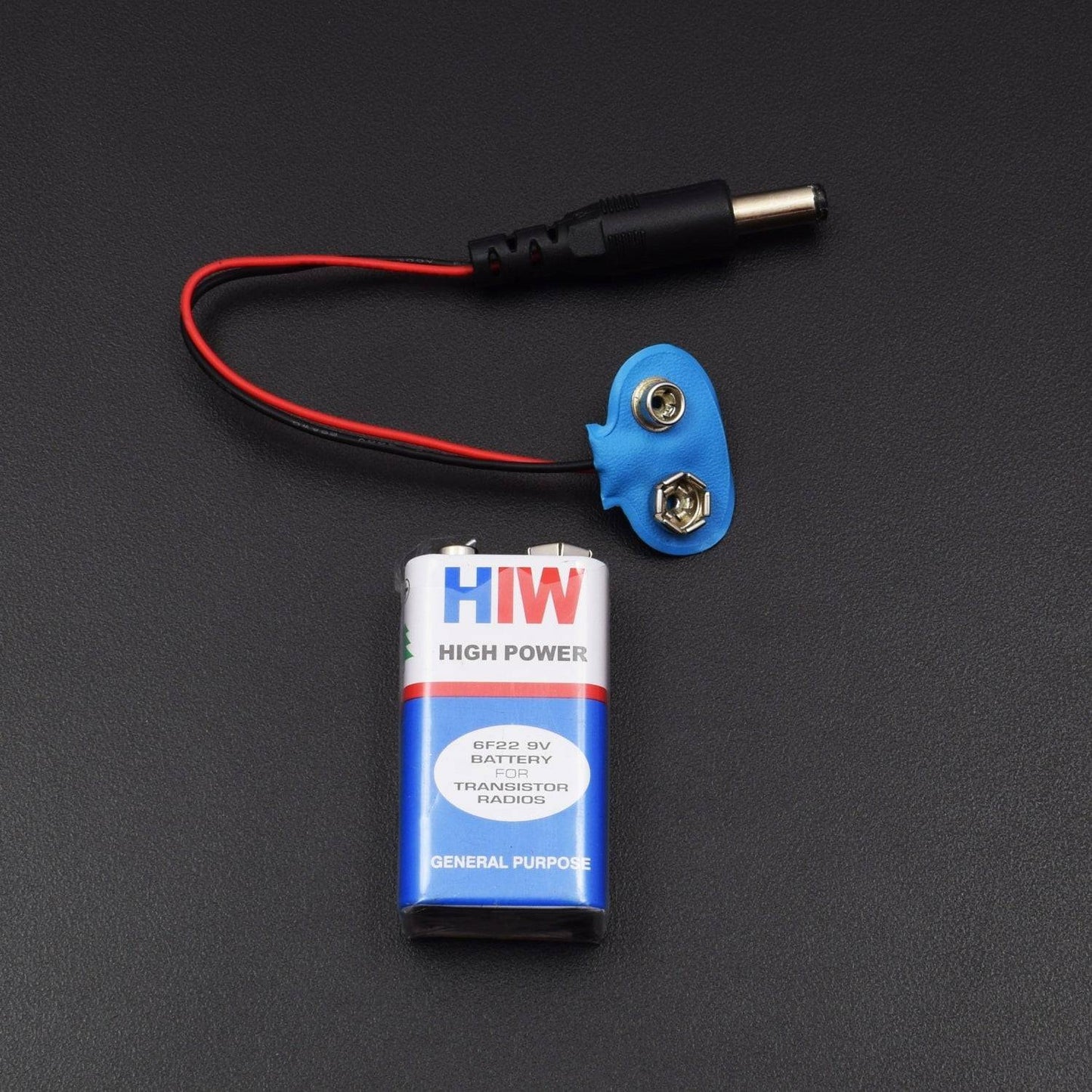
- 9v Battery with DC jack – 1
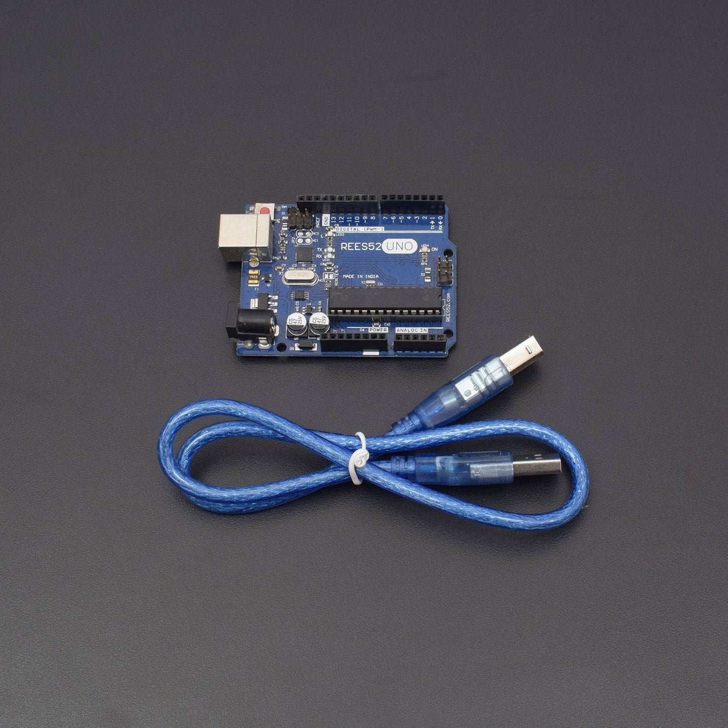
- Arduino uno with USB Cable -1
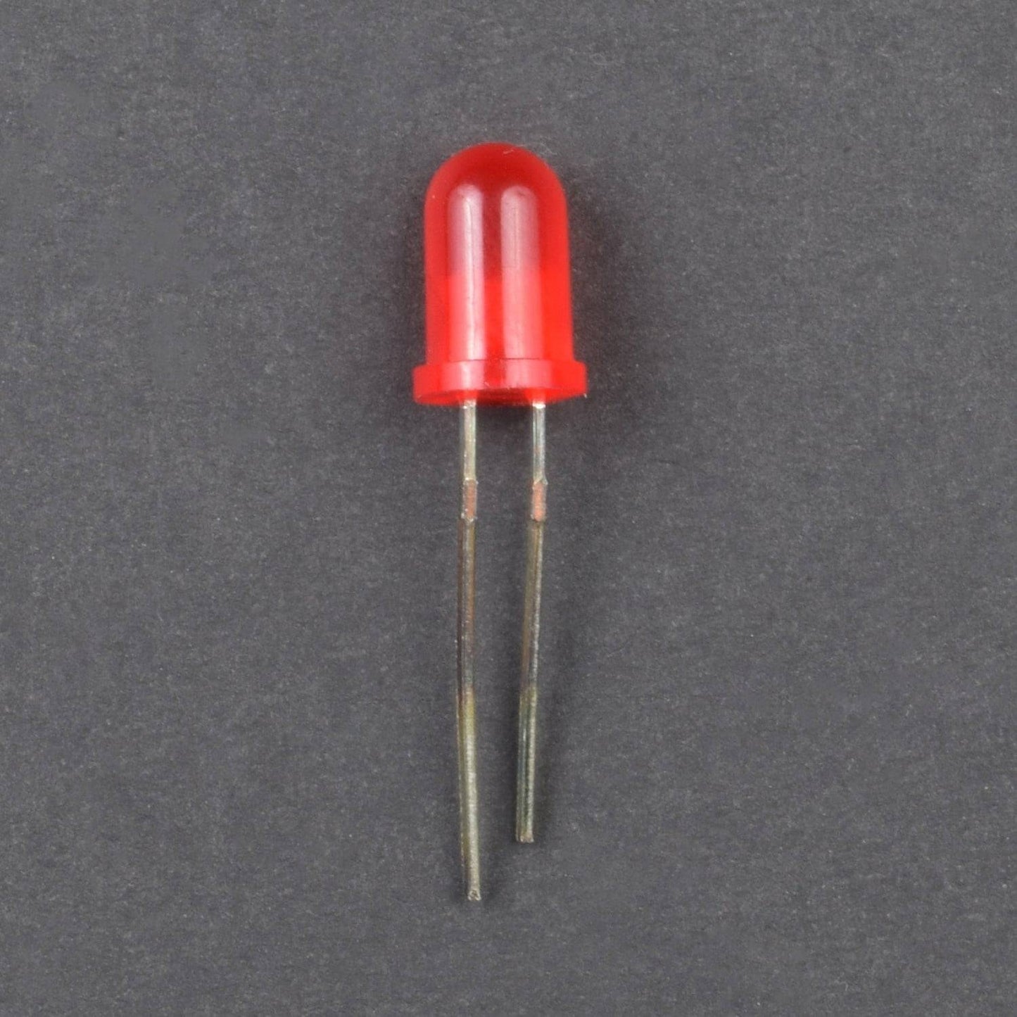
- Led – 2
- Tilt Sensor Module – 1
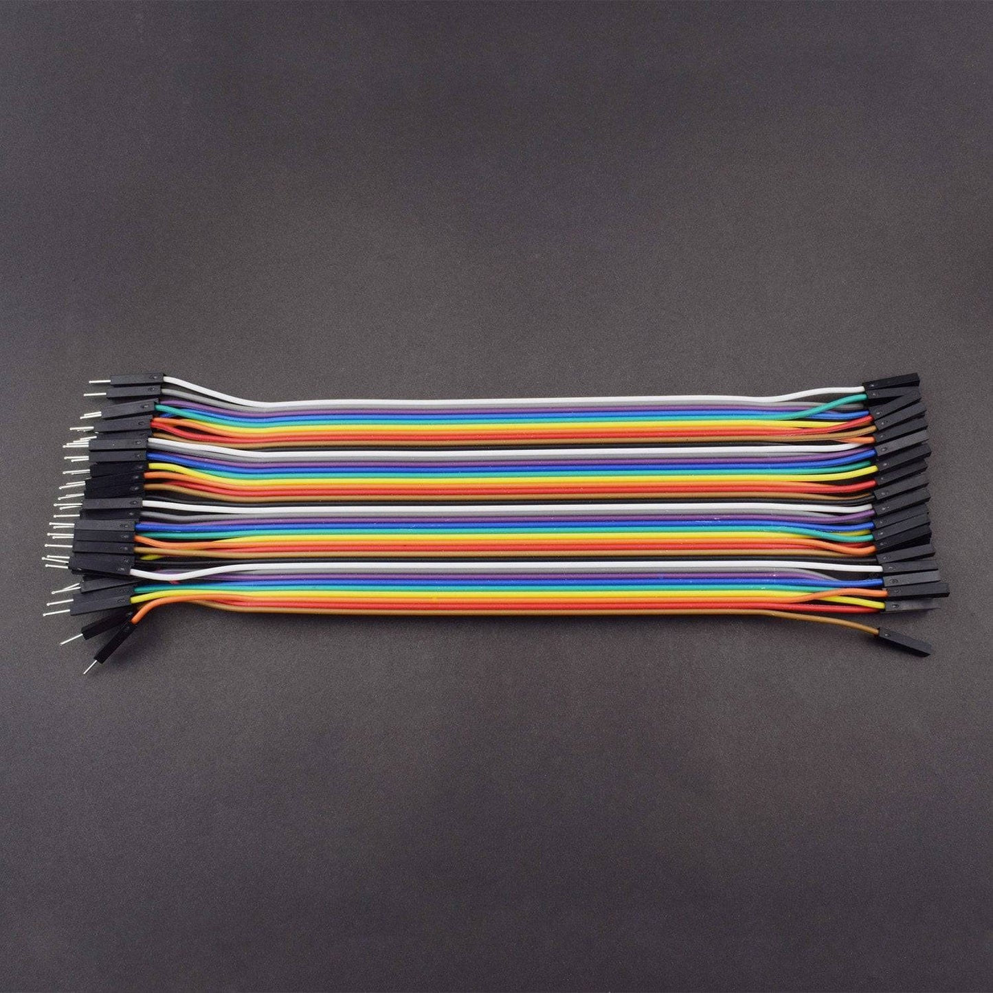
- Jumper wire (Male to female) – 40 pieces
HARDWARE REQUIRED
- 9v Battery with DC jack – 1
- Arduino uno with USB Cable -1
- Led – 2
- Tilt Sensor Module – 1
- Jumper wire (Male to female) – 40 pieces
SOFTWARE REQUIRED
Arduino IDE 1.8.5 (programmable platform for Arduino)
Click To Download :https://www.arduino.cc/en/Main/Software
PIN DESCRIPTION
TILT SENSOR


LED

CIRCUIT CONNECTION
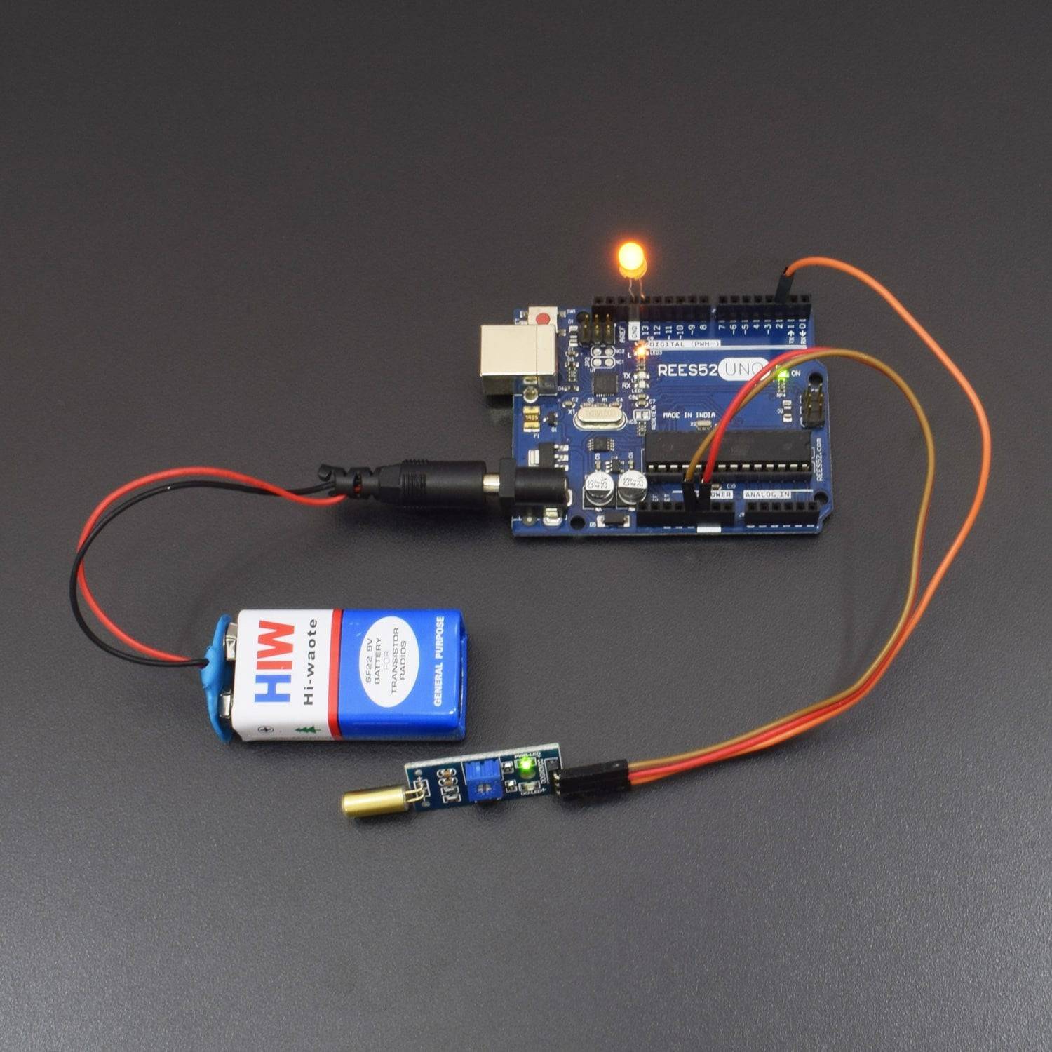
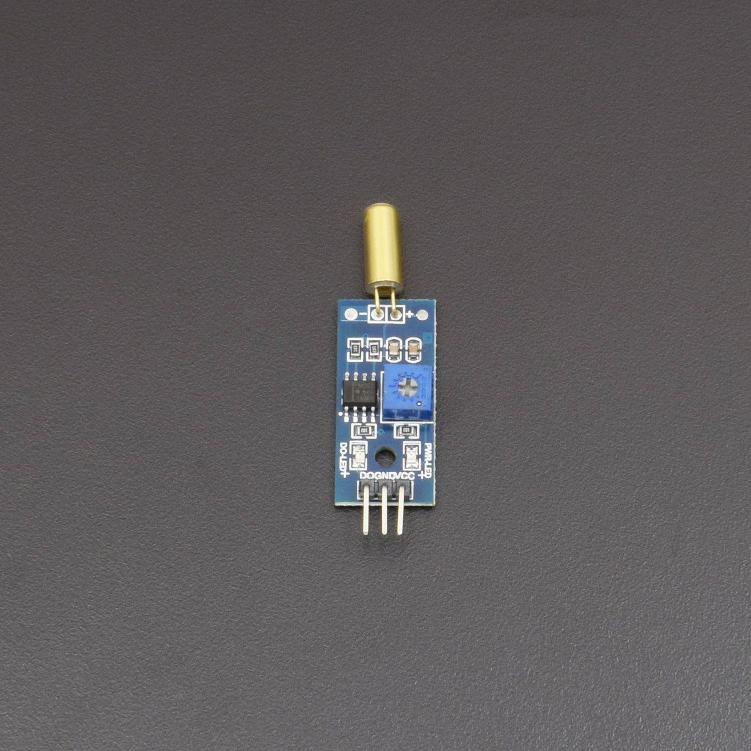
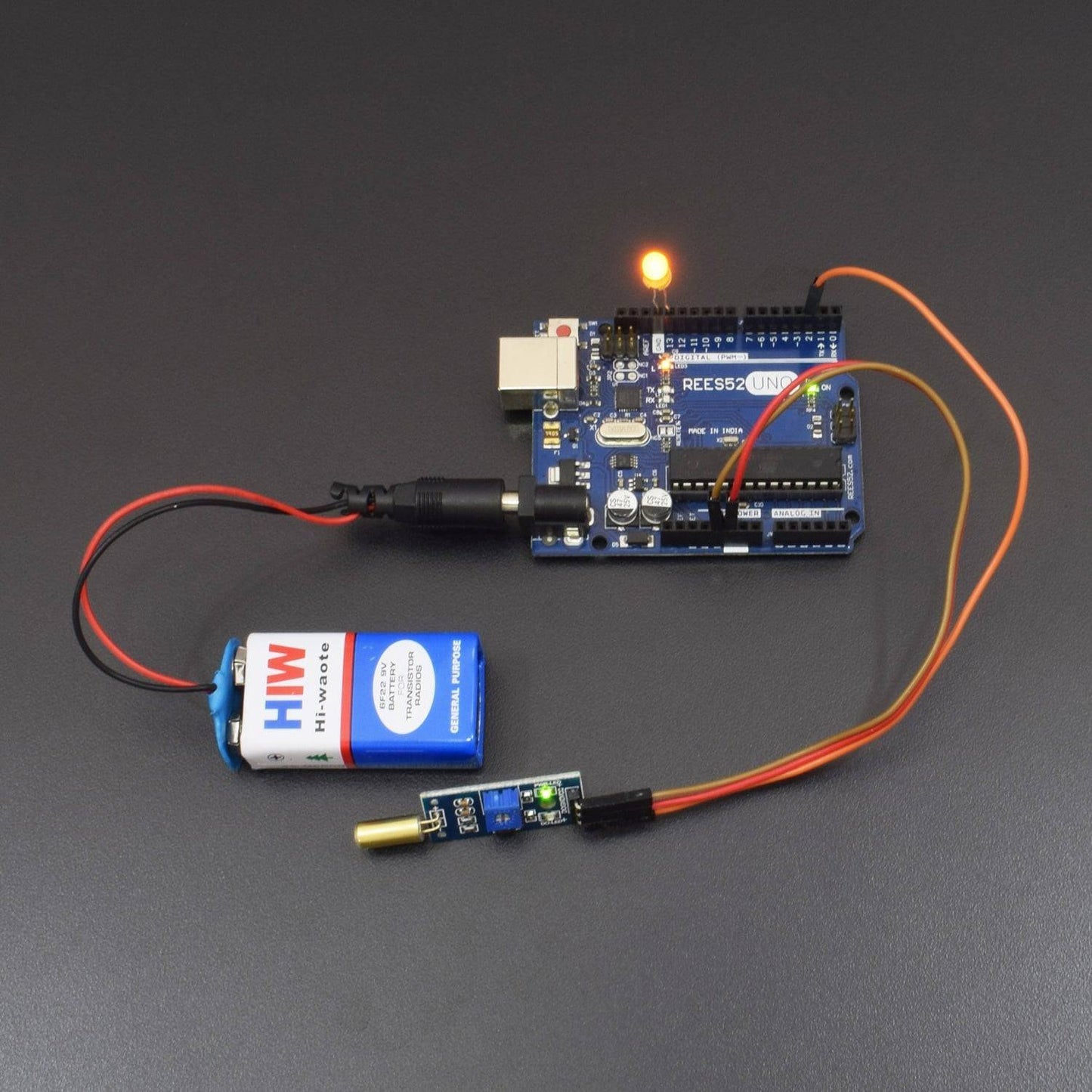
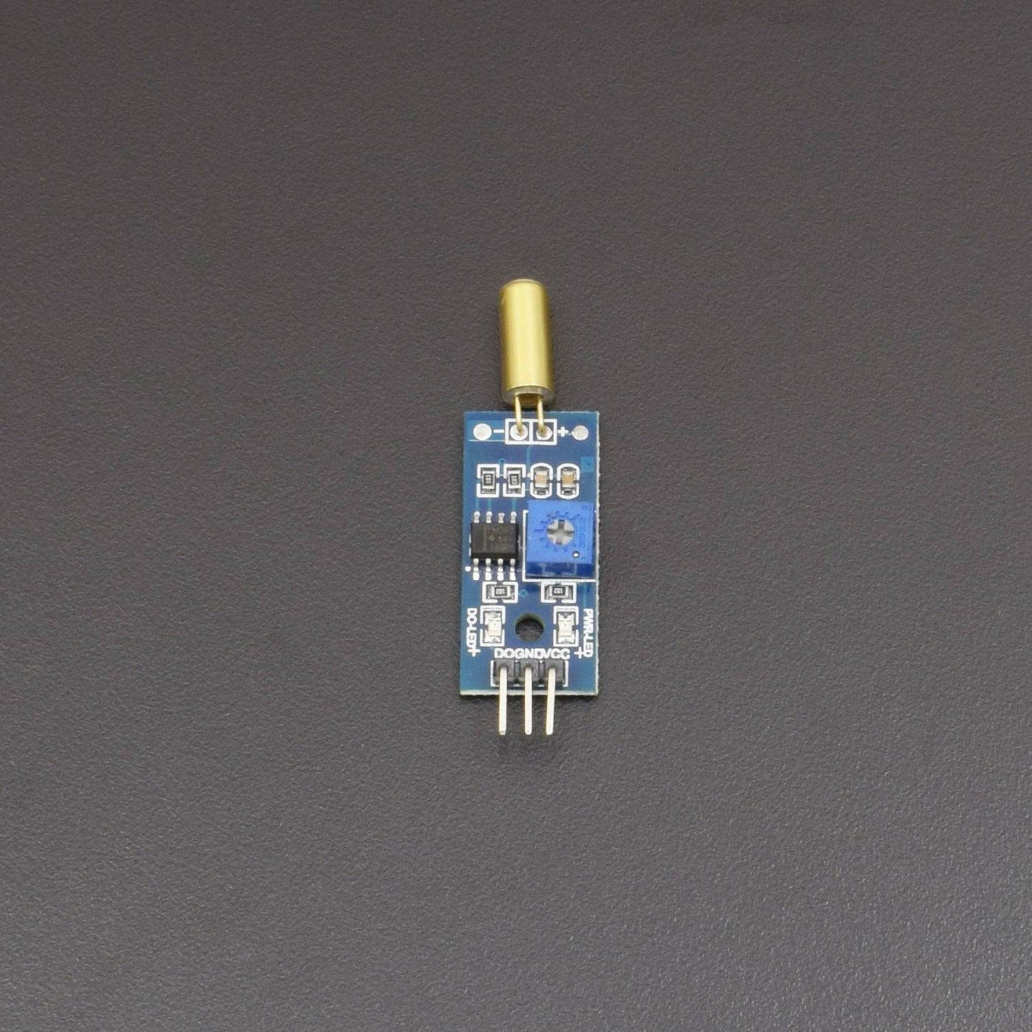
The tilt sensor module can be connected to Arduino using suitable jumper wires. First of all connect the power supply lines; VCC and GND of the module to 5V and GND of the Arduino respectively. Next link the digital output (DO) of the module to digital pin 2 (D2) and analog output (AO) to analog input 0 (A0) of the Arduino. The whole hardware should be powered by a 9V DC / USB source through the DC IN /USB socket of the Arduino board. Keep the tilt switch position in an upright position as indicated in the figure shown below.

CODE
This example code wakes the onboard indicator (LED at D13) of the Arduino when a tilt is inputted by the tilt sensor module through the occupied digital input (D2). Just copy-paste this code into your Arduino IDE, compile, and upload it to your Arduino as usual.
const int statusLED = 13;
const int switchTilt = 2;
int val = 0;
void setup(){
pinMode (statusLED,OUTPUT);
pinMode (switchTilt,INPUT);
}
void loop(){
val = digitalRead(switchTilt);
if (val == HIGH){
digitalWrite(statusLED,HIGH);
}
else {
digitalWrite(statusLED,LOW);
}
}
Note that this code does not include a “software-debounce” feature commonly used with button/switch inputs. This is not necessary here because the tilt sensor module have a built-in (1ms) “hardware debounce” arrangement using a simple RC network (R-10K & C-100n).


