


vendor-unknown
How to Use ADXL345 Digital Accelerometer with High Resolution Interfacing with Arduino Uno - KT694
How to Use ADXL345 Digital Accelerometer with High Resolution Interfacing with Arduino Uno - KT694
SKU:KT694
1000 in stock
Couldn't load pickup availability
- For Bulk Order Click Here
- Need Customer Support?
- Free Delivery Above 999/-
Note: In case you receive a damaged or faulty product, please return it in the original box with all foam and packaging. Returns will not be accepted if further damage occurs due to improper packing.
For refund/return/replacement, call us at +91 95995 94520 or email us at support@rees52.com
Delivery Time
Delivery Time
- Delivery time with the Express Shipping option is 2-3 working days, and with the Standard Shipping option is 5-6 working days. It varies based on location, reliant on courier services.
- Delivery time if the order item is on Preorder Status is 15-20 working days.
COD (Cash on Delivery)
COD (Cash on Delivery)
- For COD you have to pay extra charges of Rs 350/- before the shipment. (We will share the company QR Code, UPI ID or Account details for the same)


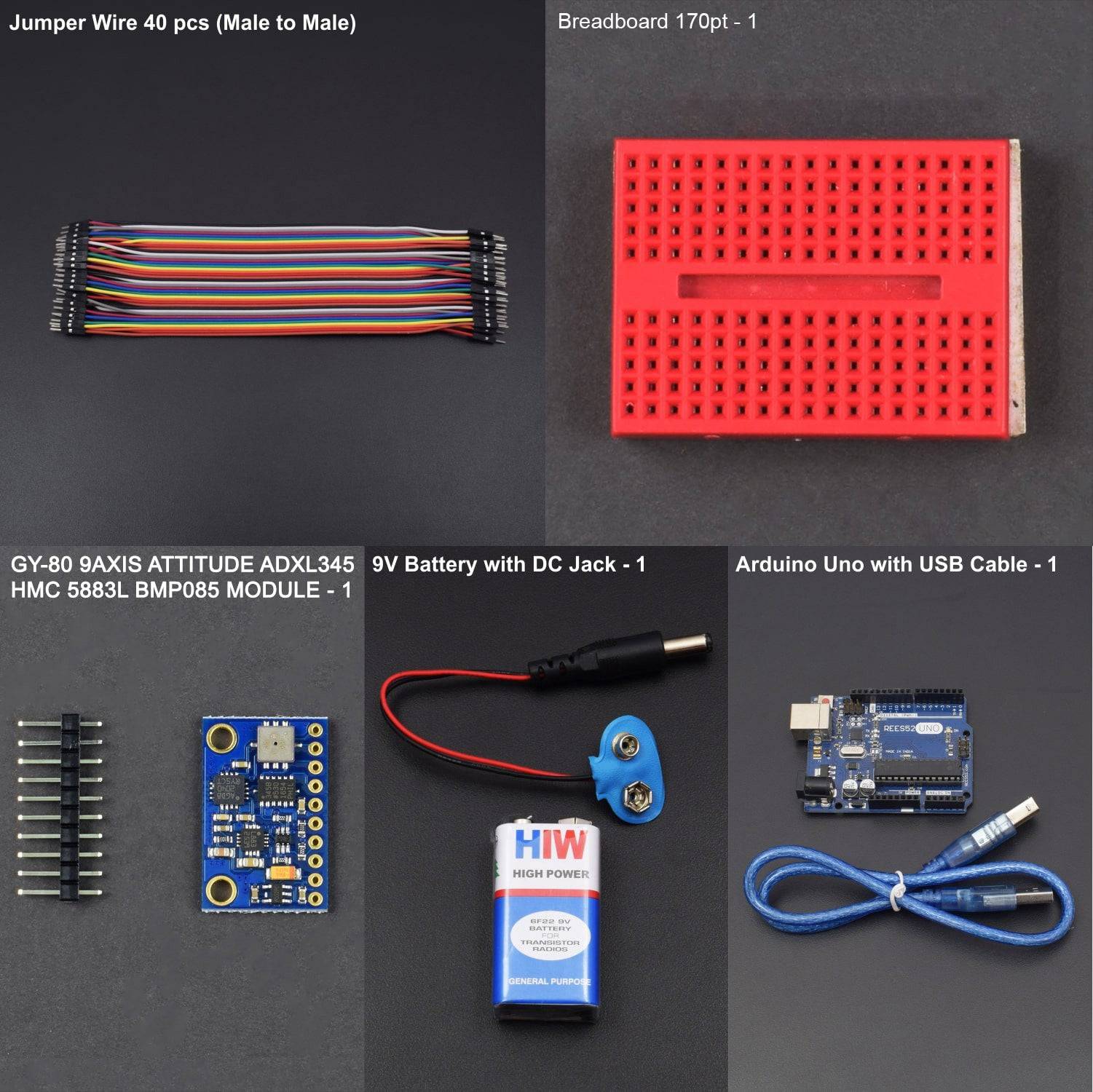
KIT INCLUDED:
- Jumper Wires (Male to Male) – 40 pcs
- Breadboard 170 points – 1
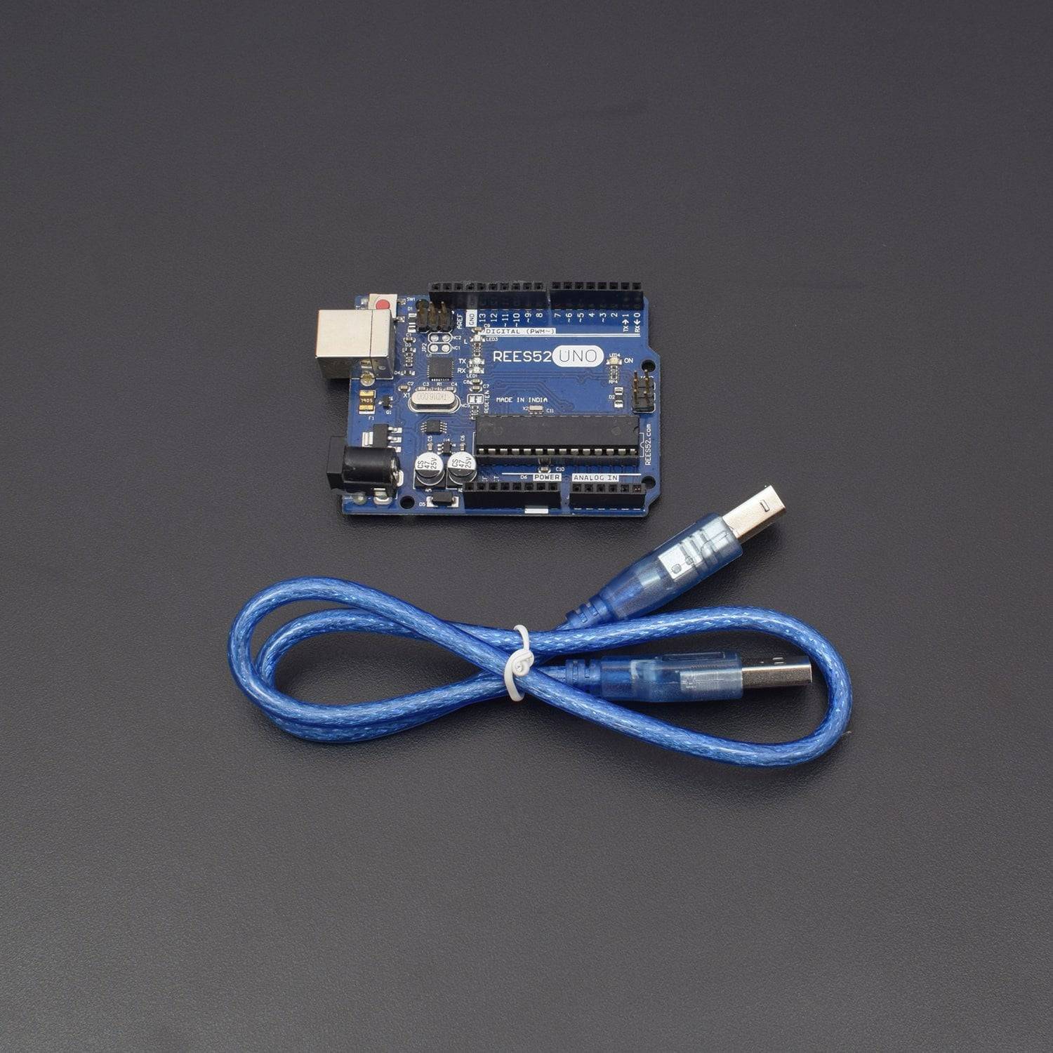
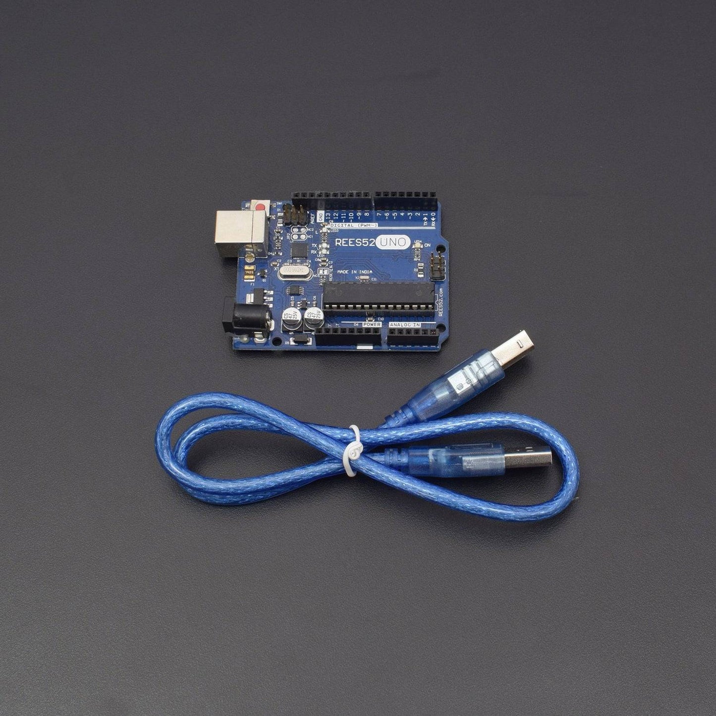
- Arduino with USB cable – 1
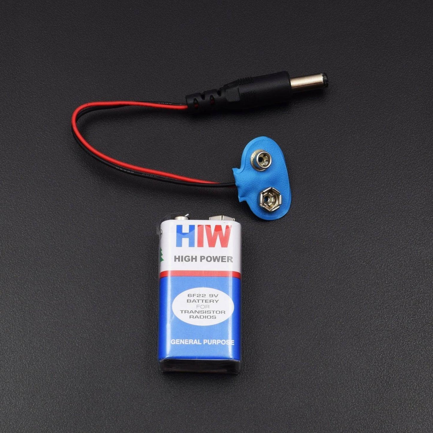
- 9V Battery with DC Jack – 1
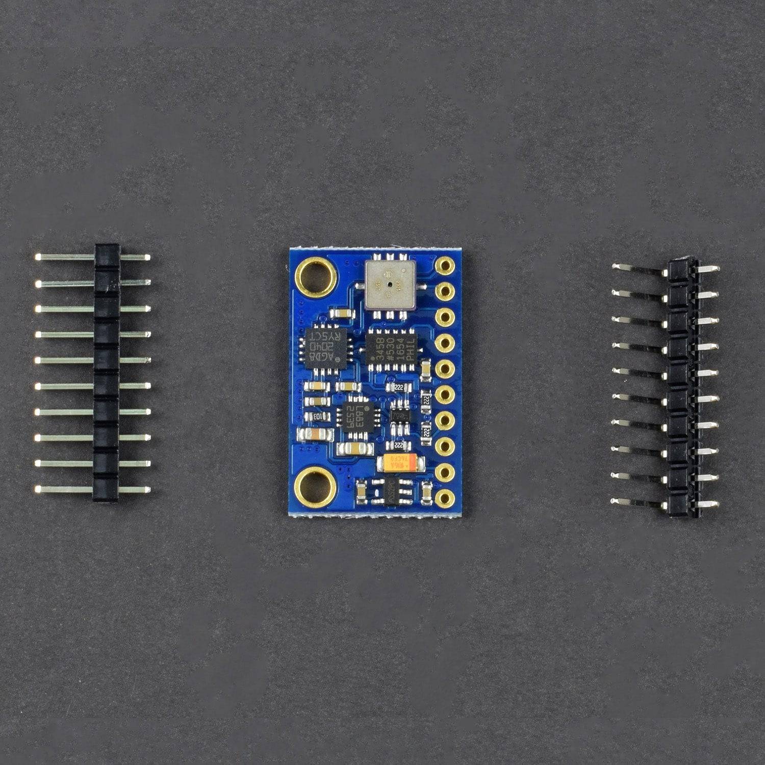
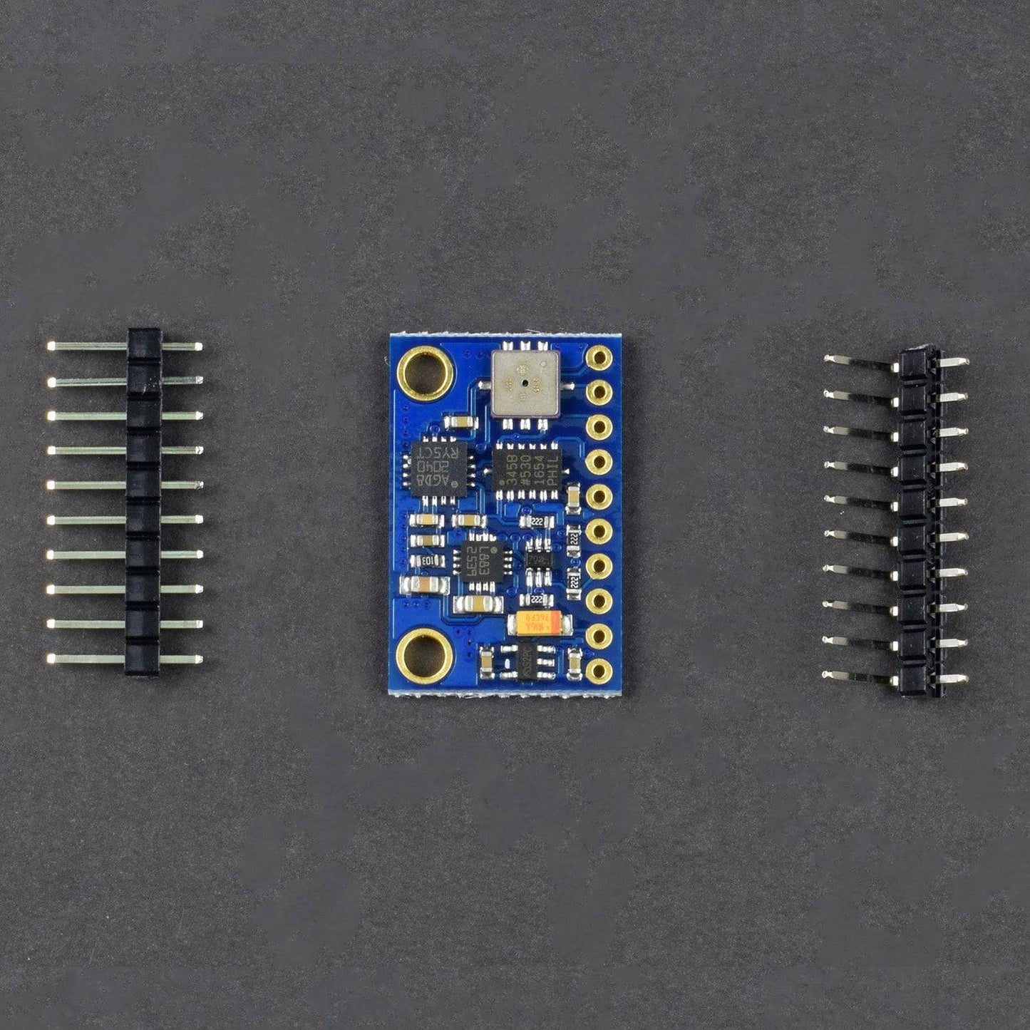
- GY-80 9-Axis Altitude ADXL345 HMC 5883L BMP085 Module – 1
HARDWARE REQUIRED
- Jumper Wires (Male to Male) – 40 pcs
- Breadboard 170 points – 1
- Arduino with USB cable – 1
- 9V Battery with DC Jack – 1
- GY-80 9-Axis Altitude ADXL345 HMC 5883L BMP085 Module – 1
SOFTWARE REQUIRED
Arduino IDE 1.8.5 (programmable platform for Arduino)
Click To Download :https://www.arduino.cc/en/Main/Software

SPECIFICATIONS
GY-80 9 Axis Altitude Sensor Module
- ADXL345 is a small and thin, low power, 3-axis accelerometer.
- It consists of high resolution of 13-bit which measures up to ±16g.
- Digital output data is formatted as 16-bit twos complement and is accessible through either a SPI (3- or 4-wire) or I2C digital interface.
- Its high resolution (4 mg/LSB) enables measurement of inclination changes less than 1.0°.
- 4x Sensors On board:
- L3G4200D (3Axis Gyroscope 2.4-3.6V)
- ADXL345 (3 Axis Accelerometer. 2v- 3.6v)
- HMC5883L (3-Axis Magnetic compass 2.16v-3.6v)
- BMP085 (Pressure Sensor. 1.62v- 3.6v)
- Interface: I2C communication protocol.
- I2C Address 0x1E is the HMC5883L
- I2C Address 0x53 is the ADXL345
- I2C Address 0x69 is the L3G4200D
- I2C Address 0x77 is the BMP085
- Operating Voltage range: 2.4V – 3.6V
- Module Size: 25.8mm * 16.8mm mounting hole 3mm
PIN DESCRIPTION
GY-80 9 Axis Altitude Sensor Module
Pin |
Name (Arduino) |
Description |
1 |
GND |
Ground (It grounds the Input and completes the circuit path) |
2 |
VCC_IN |
5V (Recommended Voltage for the given circuit) |
3 |
SDA |
Serial Data (Serial Data used for I2C communication) |
4 |
SCL |
Serial Clock (Serial Clock used for I2C serial clock) |
5 |
VCC_3.3V |
3.3V (It is the specific voltage for this particular Pin) |
6 |
M_DRDY |
Data Ready Pin (It is set when new data is available and is cleared when no new data is available) |
7 |
A_INT1 |
Interrupt 1 Output (It is Push-Pull. It is Enabled by INT_ENABLE register (Address 0x2E)) |
7 |
T_INT1 |
Interrupt 2 Output (It is Push-Pull. It is Enabled by INT_ENABLE register (Address 0x2E)) |
8 |
P_XCLR |
It Clears the BMP085 Barometer. It is used only for specific tasks. |
9 |
P_EOC |
It Ends the Conversion for BMP085 Barometer. |

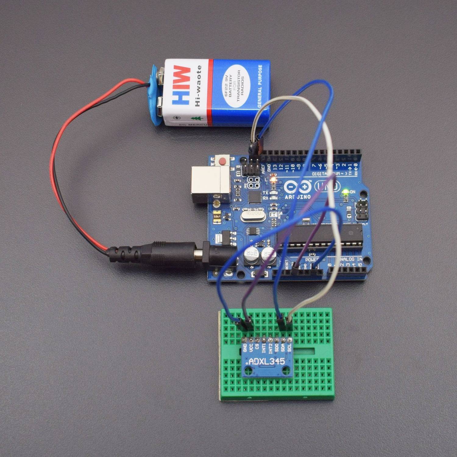
CIRCUIT CONNECTION
- The GND Pin of GY-80 will be connected to GND Pin of Arduino.
- The VCC_IN Pin of GY-80 will be connected to 5V Pin which is recommended voltage for the given circuit.
- The SDA (Serial Data) Pin of GY-80 is connected to the SDA Pin given in Arduino for I2C communication.
- The SCL (Serial Clock) Pin of GY-80 is connected to the SCL Pin of the Arduino.
- The VCC_3.3V Pin of GY-80 specifically works on 3.3V but it is not used for general purposes. It is not included in the circuit.
- The M_DRDY Pin is set when new data is available and is cleared when no new data is available. It is not included in the circuit.
- The A_INT1 and T_INT1 are the Interrupt Output Pins. Both the Pins are Push-Pull and are Enabled by INT_ENABLE register ,i.e, Address 0x2E. They are not included in the given circuit.
- The P_XCLR Pin clears the BMP085 Barometer (one of the sensor on the Board of GY-80). It is not included in the given circuit.
- The P_EOC Pin ends the conversion for BMP085 Barometer. And is used only for specific tasks. It is not included in the given circuit.
NOTE: You can also attach the SDA and SCL Pin of the GY-80 with the SDA and SCL Pin as given in the Circuit Connection.

CODE
Click to see code here: https://docs.google.com/document/d/e/2PACX-1vQ36T2R3alFcLdocoNTtxTZ1GO3tL-_GSPDKfmVNxtYLW8yxiAsoZ-RfxyUzeQ5sxtNC_meAUVeUYTm/pub?embedded=true
WORKING
Welcome to this Arduino based MPU6050 GY-80 9-Axis Altitude Accelerometer and Gyroscope Sensor Module which mainly consists of 3-axis accelerometer with high resolution of 13-bit. It measures the static acceleration of gravity in tilt-sensing applications, as well as dynamic acceleration resulting from motion or shock. The GND Pin of GY-80 is connected with the GND Pin of the Arduino Uno and the VCC_IN Pin is connected with the 5V Pin of the Arduino Uno. The SDA and SCL Pin of the GY-80 are being connected with Arduino Uno SDA and SCL Pin.
Its functioning can sense and detect the presence or lack of motion and if the acceleration on any axis exceeds a user-set level. It takes sensor measurements, calculate a human friendly value (in this case roll and pitch values) and output them to serial port. Tap sensing detects single and double taps. Free-fall sensing detects if the device is falling. These functions can be mapped to one of two interrupt output pins. If you want to check the data is correct or not, then you can also use method of Data Visualization which can be implemented by using a 3D model.
Block Diagram of the GY-80:

