


vendor-unknown
How to Identify Obstacles Using Obstacle Avoidance Sensor by Interfacing with Arduino Uno - KT718
How to Identify Obstacles Using Obstacle Avoidance Sensor by Interfacing with Arduino Uno - KT718
SKU:KT718
999 in stock
Couldn't load pickup availability
- For Bulk Order Click Here
- Need Customer Support?
- Free Delivery Above 999/-
Note: In case you receive a damaged or faulty product, please return it in the original box with all foam and packaging. Returns will not be accepted if further damage occurs due to improper packing.
If you order a product that is currently in Preorder, and the price of that item increases in the future, you will be required to pay the difference in price.
For refund/return/replacement, call us at +91 95995 94520 or email us at support@rees52.com
Delivery Time
Delivery Time
- Delivery time with the Express Shipping option is 2-3 working days, and with the Standard Shipping option is 5-6 working days. It varies based on location, reliant on courier services.
- Delivery time if the order item is on Preorder Status is 15-20 working days.
COD (Cash on Delivery)
COD (Cash on Delivery)
- For COD you have to pay extra charges of Rs 350/- before the shipment. (We will share the company QR Code, UPI ID or Account details for the same)


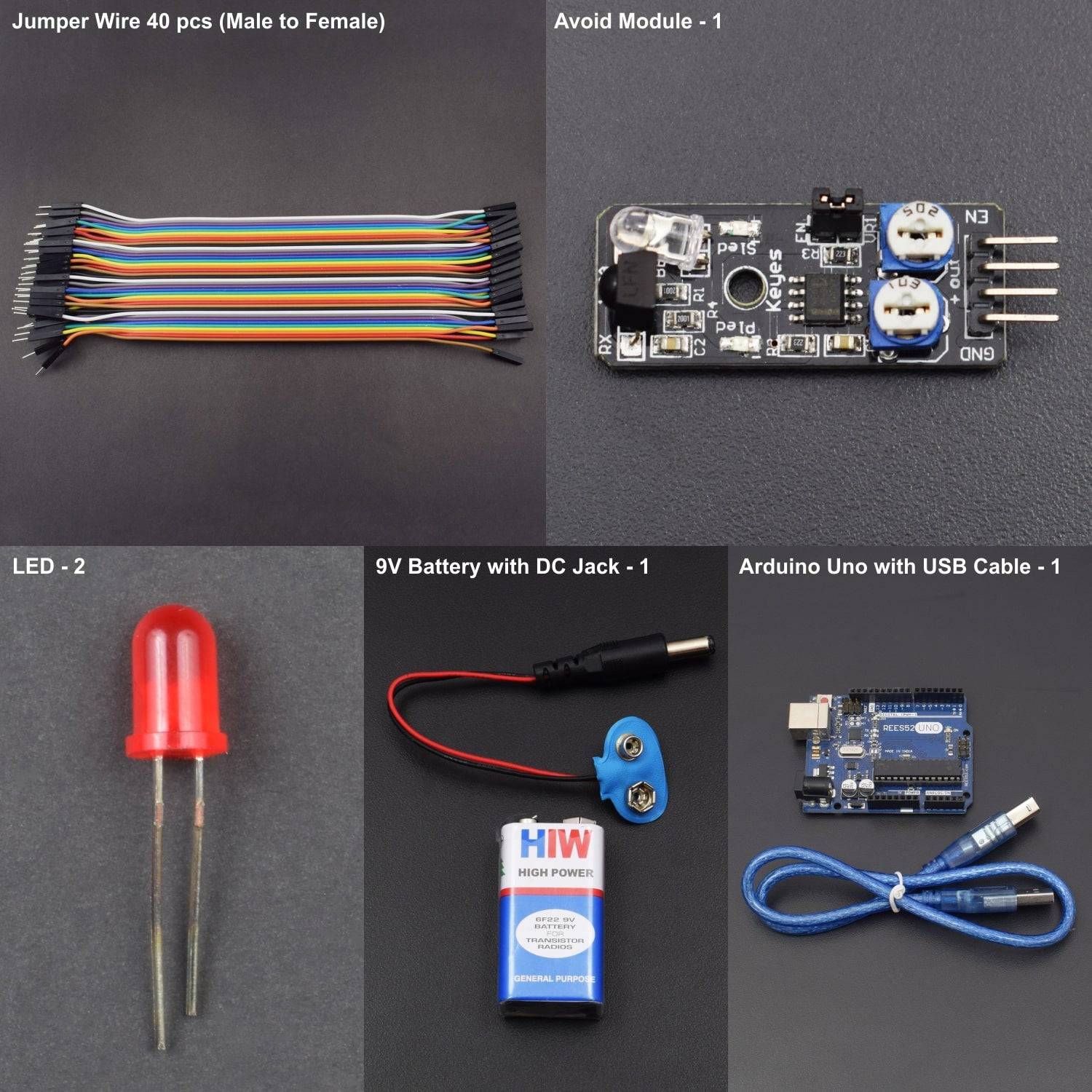
KIT INCLUDED:
• Arduino uno with USB cable- 1
• Obstacle Avoidance Sensor Module - 1
• Jumper wire(male to female) – 40 pieces
HARDWARE REQUIRED
• Arduino Uno with USB cable- 1
• Obstacle Avoidance Sensor Module - 1
• Jumper wire(male to male) – 40 pieces
SOFTWARE REQUIRED
Arduino IDE 1.8.5 (programmable platform for Arduino)
Click To Download :https://www.arduino.cc/en/Main/Software

SPECIFICATIONS
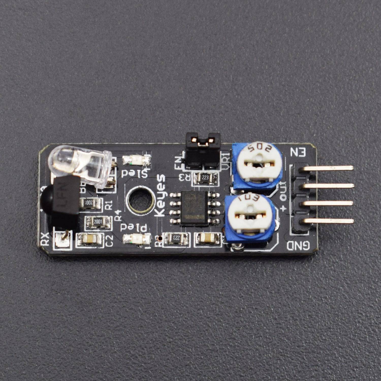
Obstacle Avoidance Sensor Module
- 3.3 to 5 V working DC voltage and I/O
- Working Current - ≥ 20mA
- 2-40cm Detection Range
- Effective angle: 35 ° with size: 28mm × 23mm
- Adjust multi-turn resistance
- Good for temperature within -10 ℃ - +50 ℃with output in TTL level
PIN DESCRIPTION
Obstacle Avoidance Sensor Module
|
Pin |
Name |
Description |
|
1 |
GND |
Ground (It grounds the Input and complete the circuit path) |
|
2 |
VCC |
3.3 V to 5 V (Recommended Voltage) |
|
3 |
OUT |
Output (It goes low when obstacle is in range) |
|
4 |
EN |
Enable (It enables the circuit)as an activation sensor PIN (putting it in HIGH) and deactivating the sensor (putting it on LOW) |
IMPORTANT:
This sensor allows you to activate and deactivate the obstacle detection by manipulating the enable-pin.
It is activated by default which means that the sensor is in detection mode by default.
If you don't want that, you need to remove the jumper with the label "EN" and put a control signal on the enable pin.

CIRCUIT CONNECTION
- An LED is attached to pin 13 of the Arduino Uno board to build a simple circuit of Obstacle Avoidance Sensor Module.
- With the LED attached to pin 13, connect pin OUT of Obstacle Avoidance Sensor to D8 of the Arduino Uno board for displaying the Output. The Output pin goes LOW, when obstacle is within range due to reduced resistance of the photodiode (component in Obstacle Avoidance Sensor).
- When the sensor detects an obstacle then the LED is turned ON automatically or else it stays off.
- The EN (Enable) pin is used to enable the circuit. The Pin EN is an activation sensor PIN (putting it in HIGH) and deactivating the sensor (putting it on LOW), but the result will be the same. When reading, the input is always 1. But is not used in the given circuit connection.

CODE
Click to see the code: https://docs.google.com/document/d/e/2PACX-1vT7bfujCSt-KnHGZmlAeqLCPp5UKSLzraCknebYG35VehDUak4sbs7W4kVZOsoweoo1YaQZH749MOlp/pub?embedded=true
WORKING


This Arduino based Obstacle Avoidance Sensor mainly consists of an infrared-transmitter, an infrared-receiver and a potentiometer. In this particular sensor module, we identify the obstacle through the use of LED which is connected to Pin 13 of Arduino Uno board. Later, when the sensor detects an obstacle it turns ON the LED and further Output is being displayed on Serial Monitor.
Its working principle depends upon the reflecting character of an object. When the light emitted by the IR LED is incident on the photodiode after hitting an object, the resistance of the photodiode falls down from a huge value. One of the input of the op – amp is at threshold value set by the potentiometer. The other input to the op-amp is from the photodiode’s series resistor. When the incident radiation is more on the photodiode, the voltage drop across the series resistor will be high. In the IC, both the threshold voltage and the voltage across the series resistor are compared. If the voltage across the resistor series to photodiode is greater than that of the threshold voltage, the output of the IC Op – Amp is high. As the output of the IC is connected to an LED, it lightens up.