


REES52
How to Control Power Supply Using IRF520 Mosfet Switch Interfacing with Arduino Uno - KT691
How to Control Power Supply Using IRF520 Mosfet Switch Interfacing with Arduino Uno - KT691
SKU:KT691
50 in stock
Couldn't load pickup availability
- For Bulk Order Click Here
- Need Customer Support?
- Free Delivery Above 999/-
Note: In case you receive a damaged or faulty product, please return it in the original box with all foam and packaging. Returns will not be accepted if further damage occurs due to improper packing.
If you order a product that is currently in Preorder, and the price of that item increases in the future, you will be required to pay the difference in price.
For refund/return/replacement, call us at +91 95995 94520 or email us at support@rees52.com
Delivery Time
Delivery Time
- Delivery time with the Express Shipping option is 2-3 working days, and with the Standard Shipping option is 5-6 working days. It varies based on location, reliant on courier services.
- Delivery time if the order item is on Preorder Status is 15-20 working days.
COD (Cash on Delivery)
COD (Cash on Delivery)
- For COD you have to pay extra charges of Rs 350/- before the shipment. (We will share the company QR Code, UPI ID or Account details for the same)
INTRODUCTION
In this illustration, we will be going to wire the IRF520 MOSFET (Metal Oxide Semiconductor Field-effect Transistor) Module Board a simple breakout board for driving higher loads. MOSFET enables you to control higher voltage projects on the microcontroller. MOSFET is also a kind of a switch that isolates the power from the main Load, when the power loads to the MOSFET it will pass the power from one to another when closed, but if the outer power source is absent your device can still draw power from microcontroller.
In this illustration we will be going to use to MOSFET Module board, we connect the power for the device you want to control to the VIN and GND then connect your control a pump, LED, or other DC device, to V+ and V- up to 24v, and ~5A. You can also power this device from your Arduino to a 5v VCC connection and GND pin.
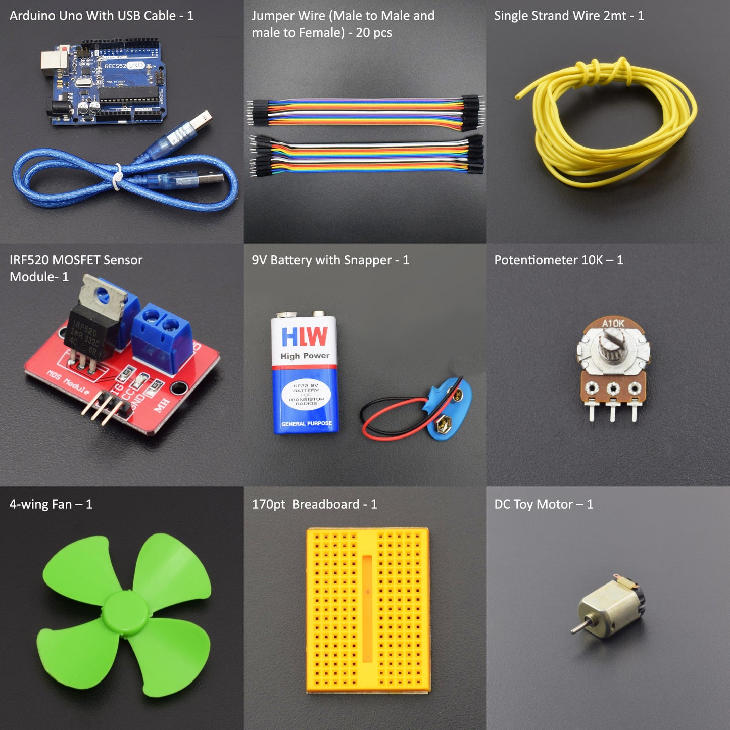
HARDWARE REQUIRED
- Arduino Uno with USB Cable – 1
- IRF520 MOSFET Sensor Module – 1
- Jumper Wires (Male to Female ) – 20 Pieces
- Jumper Wires (Male to Male) – 20 Pieces
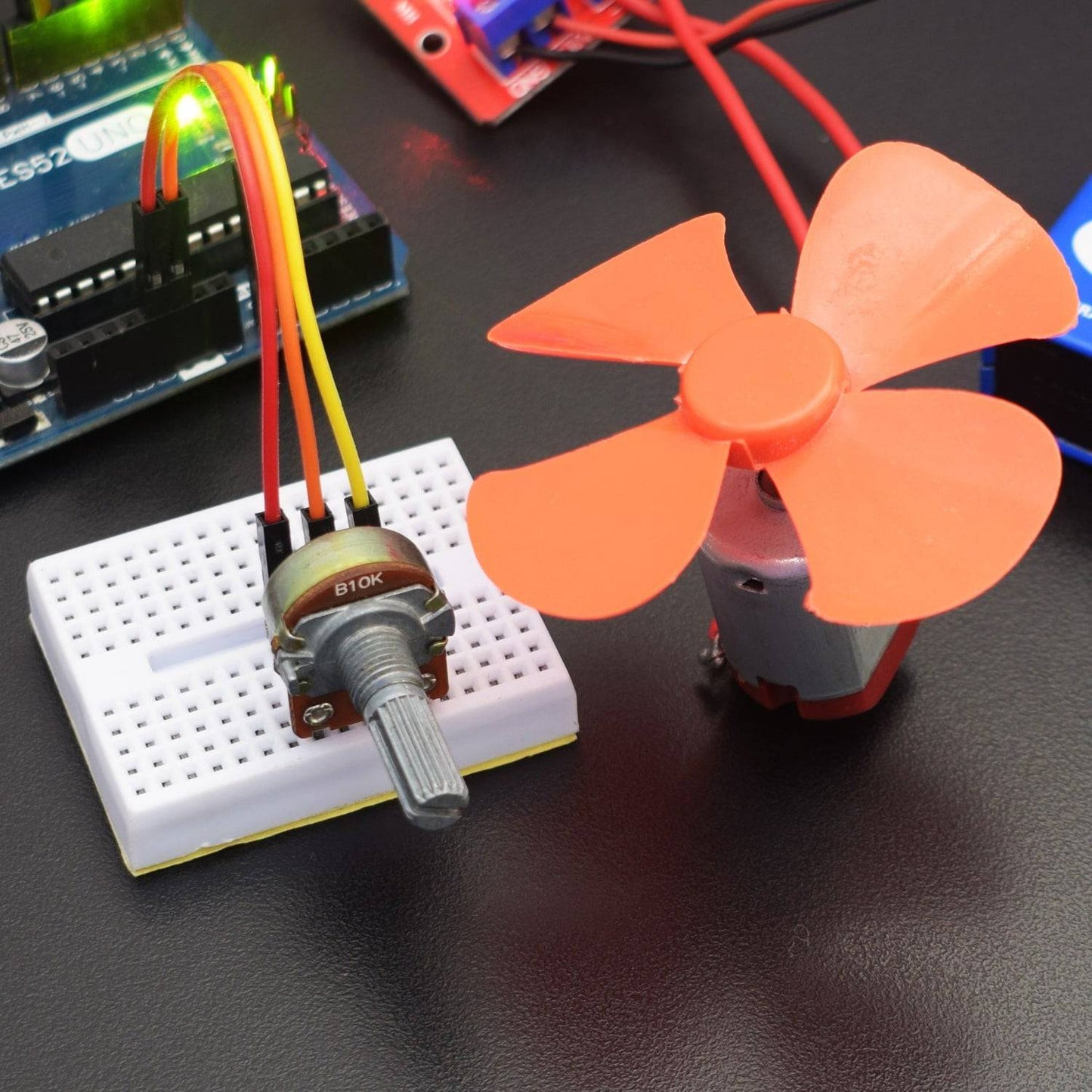
- 10k Potentiometer – 1
- DC Toy Motor – 1
- 4-Wing Fan - 1
- Single Strand Wire 2mt - 1
- 9V Battery with Snapper - 1
- 170 pt Breadboard -1
SOFTWARE REQUIRED
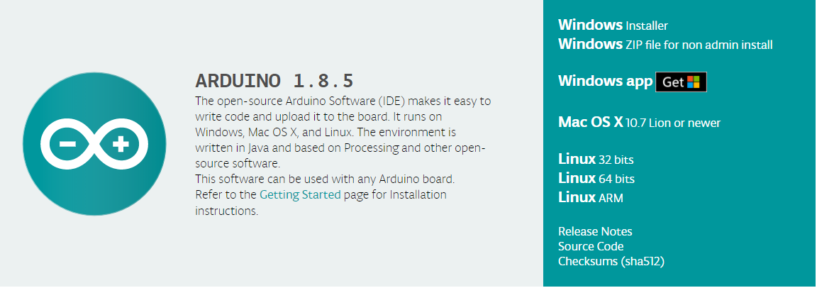
Arduino IDE 1.8.5 (programmable platform for Arduino)
Click To Download: https://www.arduino.cc/en/Main/Software
SPECIFICATIONS
IRF520 Mosfet Sensor Module:
This particular module (HCMODU0083) is a breakout board for the IFR520 MOSFET transistor. It is designed to switch heavy DC loads from a single digital pin of your microcontroller. Its main purpose is to provide a low-cost way to drive a DC motor for robotics applications, but the module can be used to control most high current DC loads.
- Size: 33.5x25.5mm
- Max load (drain) current: <5A
- Output load voltage: 0-24V
- Input Switching Voltage: Suitable for 5V microcontrollers
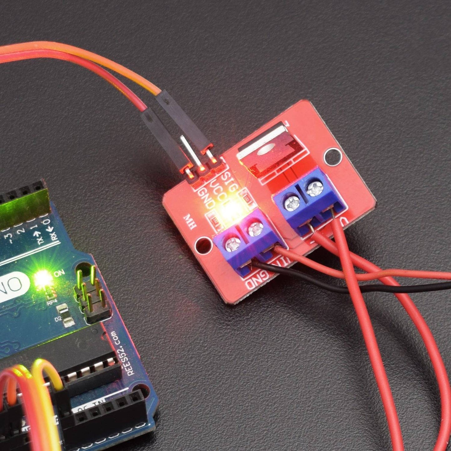
PIN DESCRIPTION
IRF520 Mosfet Sensor Module:
|
Pin |
Name |
Description |
|
1 |
GND |
Ground |
|
2 |
VCC |
5 V (Recommended Voltage) |
|
3 |
SIG |
Signal Pin (It is used to ON/OFF Mosfet switch) |
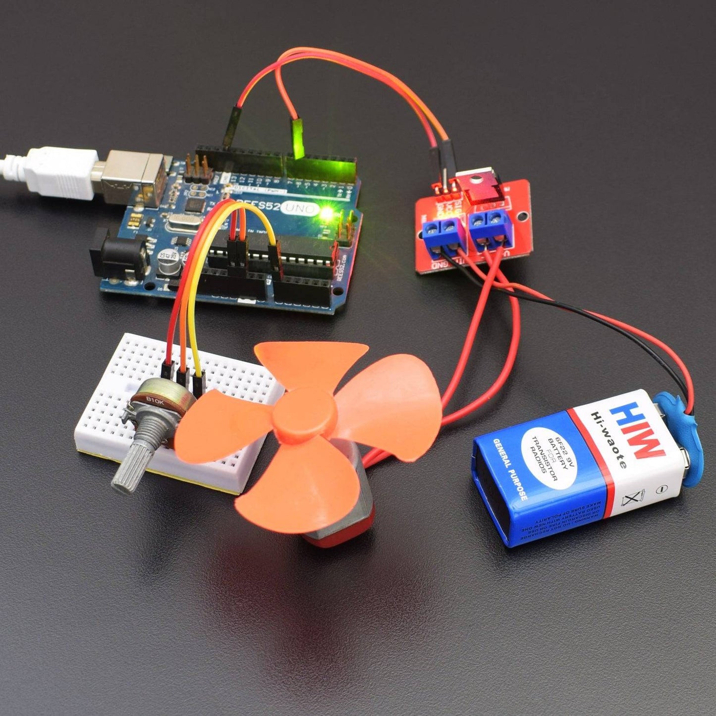
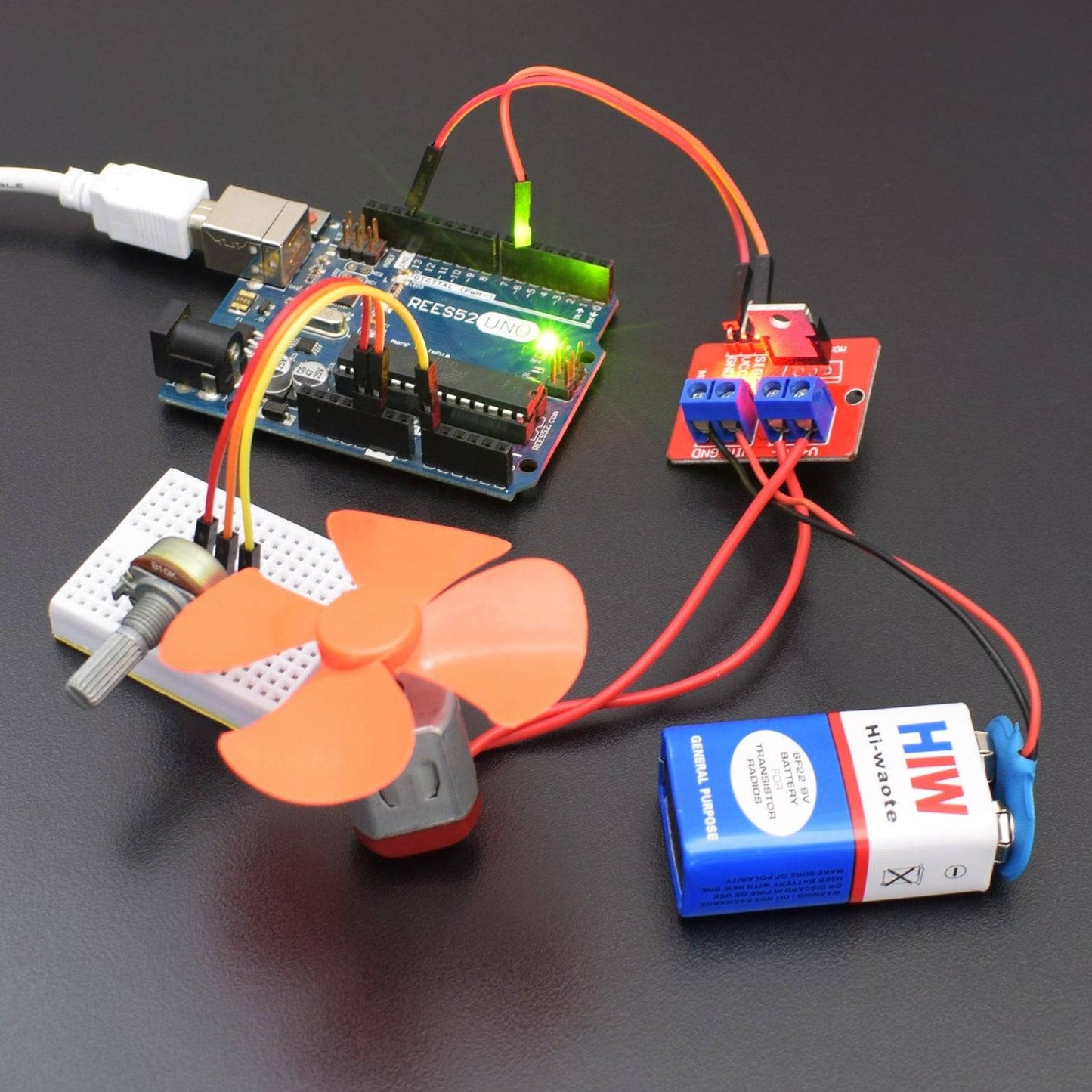
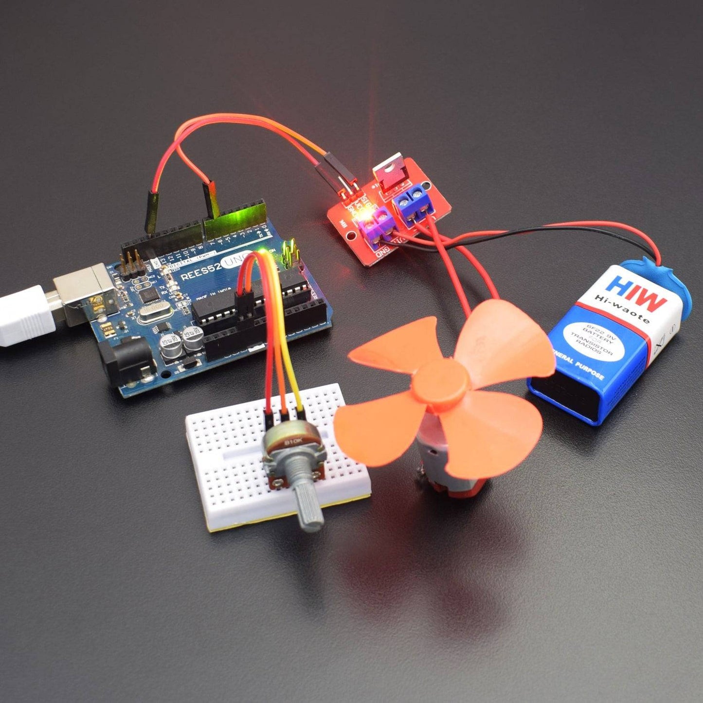
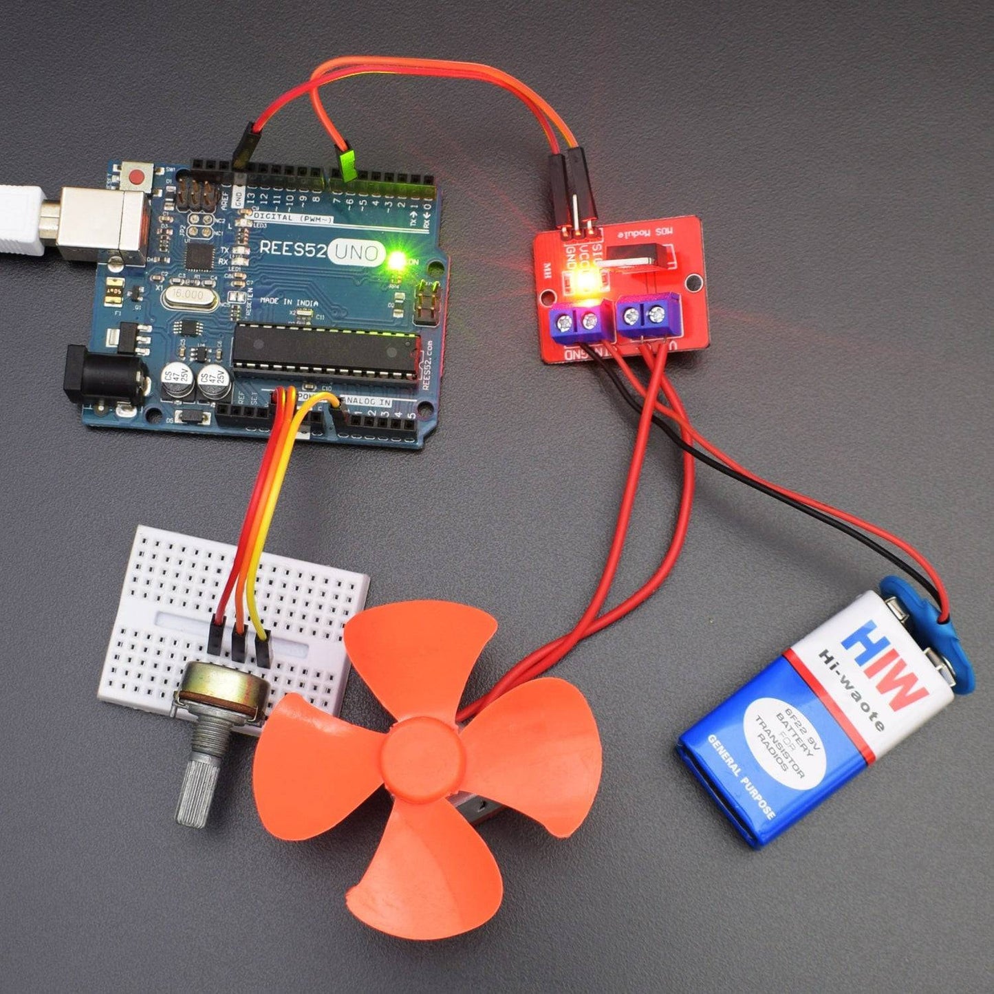
CIRCUIT CONNECTION
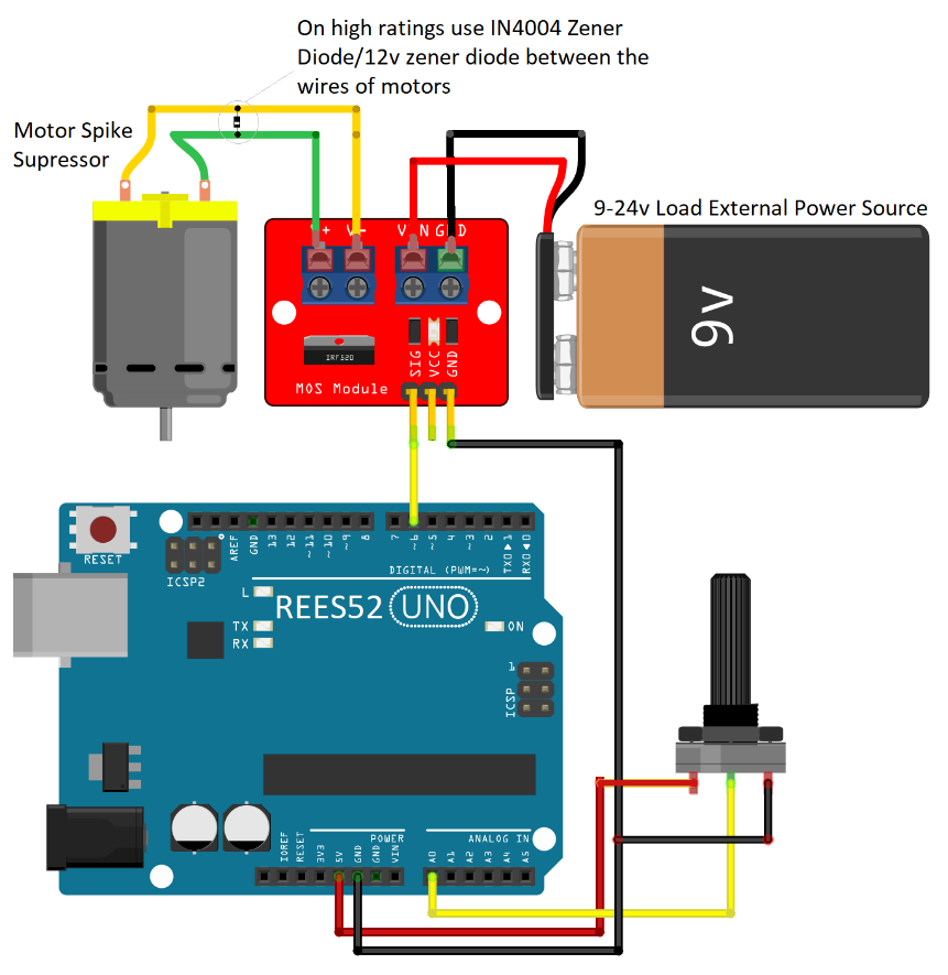
- The GND pin of the Potentiometer is attached to the GND pin of Arduino.
- The GND pin of the IRF520 Sensor Module is attached to the GND pin of Arduino.
- The VCC of the Potentiometer is attached to the 5V pin of the Arduino Board.
- The Digital I/O pin 6 of the Arduino Uno is being attached to the SIG (Signal) pin of the IRF520 MOSFET Sensor Module.
- The VIN Pin of the IRF520 MOSFET Sensor Module is being attached to the 9V Battery Power Supply.
- The Output pin of the Potentiometer is attached to the Analog Pin A0 of the Arduino Uno.
- The 4 Wing Fan is connected to the IRF520 MOSFET with its positive and negative terminals respectively.
CODE
Click here to see the code:
https://drive.google.com/open?id=1JTlKkrrSDAIh9OUX1MBmIWHjW8sBhTxu
WORKING
Welcome to this Arduino-based IRF520 MOSFET Sensor Module which mainly consists of a VCC (Power Supply), a ground (GND) pin and a Signal (SIG) Pin. It is being made to process the speed and to control DC motors. Its basic functionality is to be able to control the voltage and current flow between the source and drain.
It works almost as a switch. The working of MOSFET depends upon the MOS capacitor. The MOS capacitor is the main part of MOSFET. The semiconductor surface at the below oxide layer is located between the source and drain terminal. It can be inverted from p-type to n-type by applying positive or negative gate voltages respectively. The Potentiometer used in this particular circuit also has various applications such as LED lights, DC motors, Miniature pumps and Solenoid valves.